2AD3SA30GNSS Receiver
SUZHOU FOIF CO.,LTD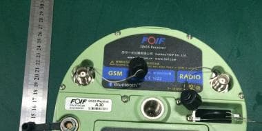
Click to zoom
Application Details
- Equipment Class
- DXT - Part 15 Low Power Transceiver, Rx Verified
- Date of Grant
- Feb 01, 2015
- Application Purpose
- Original Equipment
- Date of Application
- Feb 01, 2015
- Equipment Note
- GNSS Receiver
- Frequency Range
- 2402.00000000 - 2480.00000000
- Company
- SUZHOU FOIF CO.,LTD
- Country
- China
Documents & Files
Document Text
Text extracted from the exhibit documents filed with the FCC. Open a document above to read the original.
Users Manual
A30 GNSS Receiver User Manual Suzhou FOIF Co.,Ltd Version 1.0 System from FOIF! GNSS has revolutionized control surveys, topographic data collection and construction surveying. Purchasing the right tools for a professional job is essential in today's competitive business environment. Learning to put these tools to work quickly and efficiently will be the focus of the present manual. Compared with other GNSS products, exclusive multi-constellation (GPS+GLONASS+SBAS) capabilities. Congratulations! You have just acquired the latest dual-frequency A30 GNSS Surveying Introduction A30 is more compact and lightweight while integrating more technology, such as the A30 performs a more advanced features than A20 such as designing and operating. You will find many modifications in this instrument different from the generation A20. A30 keeps the same RTK accuracy as A20, still it gives you the accuracy with horizontal 1cm+1ppm and vertical 2cm+1ppm. Super bright OLED and voice message give you more convenience through working time. Internal memory is enlarged from 256MB to 4GB which should be enough for your whole project. There has a built-in sensor inside the instrument to help you adjusting the tilt around 3 minutes automatically by software. The biggest modification is the position of SIM slot has been changed from beside the battery to the bottom of it which can give you a more stable wcdma signal than before. FCC Statement This equipment has been tested and found to comply with the limits for a Class B digital device, pursuant to Part 15 of the FCC Rules. These limits are designed to provide reasonable protection against harmful interference in a residential installation. This equipment generates uses and can radiate radio frequency energy and, if not installed and used in accordance with the instructions, may cause harmful interference to radio communications. However, there is no guarantee that interference will not occur in a particular installation. If this equipment does cause harmful interference to radio or television reception, which can be determined by turning the equipment off and on, the user is encouraged to try to correct the interference by one or more of the following measures: -- Reorient or relocate the receiving antenna. -- Increase the separation between the equipment and receiver. -- Connect the equipment into an outlet on a circuit different from that to which the receiver is connected. -- Consult the dealer or an experienced radio/TV technician for help. This device complies with part 15 of the FCC Rules. Operation is subject to the following two conditions:(1) This device may not cause harmful interference, and (2) this device must accept any interference received, including interference that may cause undesired operation. Changes or modifications not expressly approved by the party responsible for compliance could void the user's authority to operate the equipment. This equipment complies with FCC radiation exposure limits set forth for an uncontrolled environment. This equipment should be installed and operated with minimum distance 20cm between the radiator & your body. 1 Summary 2 Unpacking the Container 2.1 Container Contents 2.2 Controllers 3 Setting Up Receivers 3.1 Base Station (External Radio) 3.2 Base Station (Power Amplifer) 3.3 Setting Up Base Station by External Radio 3.4 Rover Station 4 General Introduction 4.1 Nomenclature 4.2 Displayed Panel and Keyboard 4.3 Battery 5 Receiver Operation Contents 5.1 Buttons 5.2 LED Indicating Lights 1 3 3 5 6 6 10 14 15 16 20 22 23 24 24 26 27 Safety Information 3.5 Measuring the A ntenna Heights 19 3.6 Controller Connecting 20 5.3 Displayed Menu 6 Static Surveying 6.1 Process 6.2 Data Downloading and Format Converting 6.3 Ways of Outdoors Working for Static Surveying 6.4 GPS Network 39 39 39 42 45 52 52 52 53 54 7 Specifications 7.1 Physical Specifications 7.2 Positioning Specifications 7.3 Technical Specifications 7.4 Technical Specifications for Controllers Safety Information This manual describes the A30 GNSS Receiver. Before you use your receiver make sure that you have read and understood this manual, as well as all safety requirements. WARNING CAUTION Ignoring this indication and making an operation error could possibly result in death or serious injury to the operator. Ignoring this indication and making an operation error could possibly result in personal injury or property damage. Regulations and safety The receivers contain integra Bluetooth wireless technology, and may also send radio signal through the antenna of an internal radio-modern, or through an externally-connected data communication radio. Regulations regarding the use of the 460MHz radio-modems vary greatly from country to country. In some countries, the unit can be used without obtaining an end-user license. Other countries require end-user licensing. For licensing information, consult your local FOIF dealer. Bluetooth operates in license-free bands. Exposure to radio frequency radiation Forradio (410~430MHz/430~450MHz/450~470MHz)(RX Only) It is safety. Exposure to RF energy is an important safety consideration. Proper use of this radio modem results in exposure below government limits. The following precautions are recommended: lDO NOT operate the transmitter when someone is within 20cm of the antenna. lDO NOT collocate (place within 20cm) the radio antenna with any other transmitting lDO NOT operate the transmitter unless all RF connectors are secure and any open connectors are properly terminated. lDO NOT operate the equipment near electrical blasting caps or in an explosive atmosphere. lAll equipment must be properly grounded according to FOIF installation instructions for safe operation. lAll equipment should be serviced only by a qualified technician. For wcdma radio CAUTION - For your own safety, always observe the precautions listed here. - Always maintain a minimum separation distance of 20cm between yourself and the radiating antenna on …
Text truncated - open the document above for the full version.
Cover Letter(s)
SCS-F18: Project and Product Certification Representative Authorization Letter Page 1 of 2 Rev 5.0 775 Montague Expressway Milpitas, CA 95035 Tel: 408-526-1188 Fax: 408-526-1088 Email: [email protected] Project and Product Certification Representative Authorization Letter Revision History Reason for Amendment (current / obsolete) From To Approved Date Initial Release (obsolete) 1.0 1.0 Nov-14-2006 Revised wording (obsolete) 1.0 2.0 Sept–25-2007 Updated company template (obsolete) 2.0 3.0 Jan-31-2012 Updated letter information (obsolete) 3.0 4.0 May-23-2014 Added FCC ID field (current) 4.0 5.0 Sept 16 2014 SCS-F18: Project and Product Certification Representative Authorization Letter Page 2 of 2 Rev 5.0 SUZHOU FOIF CO.,LTD 18 Tong Yuan Road, Suzhou, China 2015-1-21 To: SIEMIC, INC. 775 Montague Expressway, Milpitas, CA 95035 USA Dear Sir/Madam, Re: Product Certification Representative Authorization Letter We, SUZHOU FOIF CO.,LTD hereby authorize SIEMIC, Inc. to act as a Certification Body for certifying for the following project(s): FCC ID: 2AD3SA30 Model: A30 Product name: GNSS Receiver Sincerely, signature : name / title: Jp Wang / Engineer address: 18 Tong Yuan Road, Suzhou, China
Cover Letter(s)
SCS-F19: Confidentiality Request Letter Page 1 of 2 Rev 3.0 775 Montague Expressway Milpitas, CA 95035 Tel: 408-526-1188 Fax: 408-526-1088 Email: [email protected] Confidentiality Request Letter Reason for Amendment (current / obsolete) Revision History Approved Date From To Initial Release (obsolete) 1.0 1.0 Nov-14-2006 Adding CFR 2.459 (obsolete) 1.0 2.0 August – 11 - 2008 Updated company template & Added text box (current) 2.0 3.0 Jan-31-2012 SCS-F19: Confidentiality Request Letter Page 2 of 2 Rev 3.0 SUZHOU FOIF CO.,LTD 18 Tong Yuan Road, Suzhou, China 2015-1-21 To: Federal Communications Commission Authorization and Evaluation Division 7435 Oakland Mills Road Columbia, MD Subject: Permanent Confidentiality Request for FCC ID: 2AD3SA30 We hereby request confidential treatment of information accompanying this application as outlined below: Block Diagram Schematics Operational Description BOM Tune up Procedurer The above materials contain trade secrets and proprietary information not customarily released to the public. The public disclosure of these materials may be harmful to the applicant and provide unjustified benefits to its competitors. The applicant understands that pursuant to Section 0.457 & 0.459 of the Rules, disclosure of this application and all accompanying documentation will not be made before the date of the Grant for this application. Sincerely, signature : name / title: Jp Wang / Engineer address: 18 Tong Yuan Road, Suzhou, China
ID Label/Location Info
Label location Model No.: A30 FCC ID: 2AD3SA30 This device complies with part 15 of the FCC Rules. Operation is subject to the following two conditions:(1) This device may not cause harmful interference, and (2) this device must accept any interference received, including interference that may cause undesired operation.
Internal Photos
WCDMA Antenna radio antenna (RX only) BT antenna
Test Report
FCC ID: 2AD3SA30 Keyway Testing Technology Co., Ltd. Report No. 15KWE012364F Page 1 of 19 FCC TEST REPORT for SUZHOU FOIF CO.,LTD GNSS Receiver Model Number: A30 FCC ID: 2AD3SA30 Prepared for : SUZHOU FOIF CO.,LTD Address : 18 Tong Yuan Road, Suzhou, China Prepared by : Keyway Testing Technology Co., Ltd. Address : Building 1, Baishun Industrial Zone, Zhangmotou Town, Dongguan, Guangdong, China Tel: 86-769-8718 2258 Fax: 86-769-8718 1058 Report No. : 15KWE012364F Date of Test : Jan. 18~25, 2015 Date of Report : Jan. 25, 2015 FCC ID: 2AD3SA30 Keyway Testing Technology Co., Ltd. Report No. 15KWE012364F Page 2 of 19 TABLE OF CONTENTS Declaration Page 1. TEST SUMMARY ........................................................................................................................ 4 2. GENERAL PRODUCT INFORMATION ....................................................................................... 4 2.1. Product Function .................................................................................................................. 4 2.2. Description of Device (EUT) ................................................................................................. 4 2.3. Difference between Model Numbers .................................................................................... 4 2.4. Independent Operation Modes ............................................................................................. 4 2.5. Test Supporting System ....................................................................................................... 5 2.6. Test Facilities ....................................................................................................................... 5 2.7. List of Test and Measurement Instruments .......................................................................... 6 3. TEST SET-UP AND OPERATION MODES ................................................................................. 7 3.1. Principle of Configuration Selection ...................................................................................... 7 3.2. Block Diagram of Test Set-up .............................................................................................. 7 3.3. Test Operation Mode and Test Software .............................................................................. 7 3.4. Special Accessories and Auxiliary Equipment ...................................................................... 7 3.5. Countermeasures to Achieve EMC Compliance ................................................................... 7 3.6. Test Environment: ................................................................................................................ 7 4. EMISSION TEST RESULTS ........................................................................................................ 8 4.1. Radiated Emission Test ....................................................................................................... 8 5. 20DB OCCUPY BANDWIDTH ................................................................................................... 14 5.1. Limits ................................................................................................................................. 14 5.2. Test setup .......................................................................................................................... 14 6. BAND EDGE COMPLIANCE TEST ........................................................................................... 17 6.1. Limits ................................................................................................................................. 17 6.2. Test setup .......................................................................................................................... 17 7. ANTENNA REQUIREMENTS .................................................................................................... 18 7.1. Limits ................................................................................................................................. 18 7.2. Result................................................................................................................................. 18 8. PHOTOGRAPHS OF TEST SET-UP ......................................................................................... 19 9. PHOTOGRAPHS OF THE EUT ................................................................................................. 19 FCC ID: 2AD3SA30 Keyway Testing Technology Co., Ltd. Report No. 15KWE012364F Page 3 of 19 Keyway Testing Technology Co., Ltd. Applicant: Address: SUZHOU FOIF CO.,LTD 18 Tong Yuan Road, Suzhou, China Manufacturer: Address: SUZHOU FOIF CO.,LTD 18 Tong Yuan Road, Suzhou, China E.U.T: GNSS Receiver Model Number: A30 Trade Name: Serial No.: ------ Date of Receipt: Jan. 17, 2014 Date of Test: Jan. 18~25, 2015 Test Specification: FCC Part 15, Subpart C Section 15.249: 2014 ANSI C63.4:2003 Test Result: The equipment under test was found to be compliance with the requirements of the standards applied. Issue Date: Jan. 25, 2015 Tested by: Reviewed by: Approved by: Jack Bu / Engineer Andy Gao / Supervisor Jade Yang/ Supervisor Other Aspects: None. Abbreviations: OK/P=passed fail/F=failed n.a/N=not applicable E.U.T=equipment under tested This test report is based on a single evaluation of one sample of above mentioned products. It is not permitted to be duplicated in extracts without written approval of Keyway Testing Technology Co., Ltd. FCC ID: 2AD3SA30 Keyway Testing Technology Co., Ltd. Report No. 15KWE012364F Page 4 of 19 1. TEST SUMMARY Test Items Test Requirement Result Conducted Emissions 15.207 N/A Radiated Emissions 15.209 15.249(a)(d) PASS 20dB Bandwidth 15.249 PASS Emissions from out of band 15.249(d) PASS Antenna Requirement 15.203 PASS Remark: N/A means not application. 2. GENERAL PRODUCT INFORMATION 2.1. Product Function Refer to Technical Construction Form and User Manual. 2.2. Descriptio…
Text truncated - open the document above for the full version.
Test Setup Photos
Radiated Emission
Contact Information
Applicant
Jp Wang(Engineer)
Test Firm
Keyway Testing Technology Co., Ltd.Jade Yang
Technical Specifications
| # | Rule Parts | Frequency Range | Power Output |
|---|---|---|---|
| 1 | 15C | 2.40 GHz - 2.48 GHz | - |
Other Applications from SUZHOU FOIF CO.,LTD
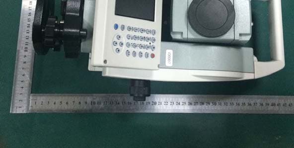
2AD3SRTS352
Feb 01, 2015Total Station
Equipment Class
DXT - Part 15 Low Power Transceiver, Rx Verified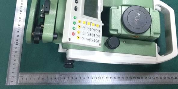
2AD3SRTS102
Feb 01, 2015Total Station
Equipment Class
DXT - Part 15 Low Power Transceiver, Rx Verified