2AD3SRTS352Total Station
SUZHOU FOIF CO.,LTD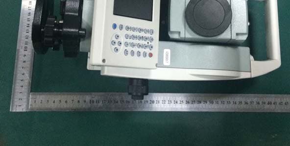
Click to zoom
Application Details
- Equipment Class
- DXT - Part 15 Low Power Transceiver, Rx Verified
- Date of Grant
- Feb 01, 2015
- Application Purpose
- Original Equipment
- Date of Application
- Feb 01, 2015
- Equipment Note
- Total Station
- Frequency Range
- 2402.00000000 - 2480.00000000
- Company
- SUZHOU FOIF CO.,LTD
- Country
- China
Documents & Files
Document Text
Text extracted from the exhibit documents filed with the FCC. Open a document above to read the original.
Users Manual
RTS 350 Series Total Station Instruction Manual RTS352 RTS355 Version1.0e English Suzhou FOIF Co., Ltd. 1 Dear Customer: Congratulations! We, FOIF are proud to present you with an RTS350 instrument. Your total station is a rugged and reliable instrument whose performance and design are not surpassed. To fully appreciate and protect your investment, we suggest that you take the necessary time to read and fully understand this manual. We have a dedicated service organization. If the need arises, please don’t hesitate to call us. Thank you for your trust and confidence. 2 NOTE: Don’t collimate the sun directly Avoid insolating the instrument, and don’t collimate the sun directly for protecting eyes and instrument. Set up the instrument on the tripod When using it please insure the connection between tripod and instrument is firm. It is better to work with wooden tripod for the measurement accuracy. Assemble the tribrach on the instrument The setting of tribrach would influence the accuracy. The tribrach should be check frequently, the screw which connects the tribrach and alidade must be locked tightly. And the central fixing screw should be tight. Avoiding the librations on the instrument When transporting, keep the instrument in the case and try your best to lighten librations. Carry the instrument When carrying,the instrument handle must be held tight. High temperature condition If put the instrument in high temperature condition for a long time, it is bad for the instrument performance. Temperature changing sharply The sharp temperature changing on the instrument or prism will shorten the distance measurement range, for example, after taking the instrument out from a warm car to a cold condition, wait for some time, it can be used when it adapts to the surrounding condition. Check the battery power Before using it, you should check the power whether it is enough. Take out the battery It is not suggested to take out the battery when the instrument is on, otherwise, the stored data may be lost, so it is better to replace the battery after power off the instrument. Stored data responsibility FOIF should not be held liability for the lost data because of wrong operation. The noise from the instrument When the instrument is working, it is normal if you hear the noise from instrument motor, it will not affect the instrument work. 3 Definition of Indication For the safety of your product and prevention of injury to operators and other persons as well as prevention of property damage, items which should be observed are indicated by an exclamation point within a triangle used with WARNING and CAUTION statements in this manual. The definitions of the indication are listed below. Be sure you understand them before reading the manual’s main text. PRECAUTIONS FOR SAFE OPERATION ●Only FOIF authorized distributors can disassemble or rebuilt the instrument. ●Do not collimate the sun directly. The eye injury or blind could result. ●Cover the charger maybe result fire when charging. ●If use defection power cable, socket or plug, there is danger of fire, or electronic shock. ●Using wet battery or charger maybe result fire, or electronic shock. ●Do not close the instrument to burning gas or liquid, and do not use the instrument in coal mine. Blast could be result. ●Do not put the battery in the fire or high temperature condition. Explosion, damage could result. ●If use the battery which is not specified by FOIF, there is a danger of fire, electric shock or burn. ●If use the power cable which is not specified by FOIF, there is a danger of fire. ●If short circuit of the battery, there is a danger of fire.. ● When this product encounters disturbance of severe Electrostatic Discharge, perhaps it will have some degradation of performance like switching on/off automatically and so on. WARNING: CAUTION: ! WARNING ! ! Ignoring this indication and making an operation error could possibly result in death or serious injury to the operator. Ignoring this indication and making an operation error could possibly result in personal injury or property damage. 4 ●If touch the instrument with wet hand, there is danger of electric shock. ●Stand or seat on the carrying case, or turn over the carrying case arbitrarily, the instrument maybe damaged. ●Be careful of the tripod tiptoe when setup or move it. ●Drop the instrument or the carrying case, or use defective belt, agraffe or hinge, instrument damage could result. ●Do not touch liquid leaking from the instrument or battery. Harmful chemicals could cause burn or blisters. ●Please assemble the tribrach carefully, if the tribrach is not stable, series damage could result. ●Drop the instrument or tripod, series damage could result. Before use it, check the central screw is tight. User 1) This product is for professional user only! The user is required to be a qualified surveyor or have a good knowledge of surveying, in order to understand the user manual and safety instructions, before operating, inspecting or adjusting. 2) Wear the required protectors (safety shoes, helmet, etc.) when operating. Exceptions from Responsibility 1) The user of this product is expected to follow all operating instructions and make periodic checks of the product’s performance. 2) The manufacturer assumes no responsibility for results of a faulty or intentional usage or misuse including any direct, indirect, consequential damage, and loss of profits. 3) The manufacturer assumes no responsibility for consequential damage, and loss of profits by any disaster, (an earthquake, storms, floods etc.). 4) The manufacturer assumes no responsibility for any damage, and loss of profits due to a change of data, loss of data, an interruption of business etc., caused by using the product or an unusable product. 5) The manufacturer assumes no responsibility for any damage, and loss of profits caused by usage except for explained in the user manual. 6) The manufacturer assumes no responsibility for damage caused by …
Text truncated - open the document above for the full version.
Users Manual
42 4.4.7 Missing Line Measurement (MLM) The Missing Line Measurement program calculates the horizontal distance (dHD), slope distance (dSD) and elevation (dVD) between two target prisms. The instruemt can accomplish this in two ways: 1.MLM Method (A-B, A-C): Measurement is A-B, A-C, A-D, ......... 2.MLM Method (A-B, B-C): Measurement is A-B, B-C, C-D, ......... 43 Operation steps Keys Display Under distance ① measurement, click “MLM” key to activate Missing Line Measurement. 【MLM】 Select method (A②-B, A-C) with stylus. Collimate prism A,click ③ “M.Dist” key. Horizontal distance between instrument and prism A will be shown. 【M.Dist】 44 Collimate prism B,click ④ “M.Dist” key. 【M.Dist】 Click “⑤Continue” key,then horizontal distance(dHD), elevation difference(dVD) and slope distance (dSD) between prism A and prism B will display. 1※) 【Continue】 In order ⑥to calculate the horizontal distance between points A and C,collimate prism C,and click “M.Dist” key again.Thus horizontal distance between instrument and prism C will be shown.. 【M.Dist】 45 Click “⑦Continue” key,then dHD, dVD and dSD between prism A and prism C will be shown. 【Continue】 1※)Click “Exit” key to return main menu. ●Procedure of MLM Method (A-B, B-C) is completely same as Method (A-B, A-C) Method. 4.4.8 Line-height Measurement This function is applied for measuring and determining a height of line(like electric wire)above ground which is hard to reach. See following image, L is point on the overhead line, G is projective point on the ground, which is also difficult to set target, A and B are baseline which are set up in a certain distance under line. After measuring horizontal distances from instrument to prisms A/B and confirm the base line, VD between A and B, VD between L and G, HD between instrument and L(G),offset distance from A to L(G) will be determined and shown. 46 Operation steps Keys Display Under distance ① measurement mode, click “LHM” key to activate line-height measurement program. 【LHM】 Select “With PH” button ② with stylus. With PH 47 Click “③Setup” key to input instrument height(IH) and prism height(PH).After that click “Enter” key. 【Setup】 Collimate prism A,④ click “Measure” key, and distance measurement begins. After that click “Continue” key. 【Measure】 Collimate prism B,⑤ click “Measure” key, and distance measurement begins. 【Measure】 48 After measure⑥ment click “Continue” key. 【Continue】 ⑦Collimate point L on overhead line. The screen displays measuring data of collimating L. VD:Vertical distance between A and L. HD:Horizontal distance between instrument and L. Off:Horizontal distance between A and L. ⑧Click “Continue” key which is used for measuring height between overhead line and ground. Operation steps: ●Collimate point on overhead line before clicking “Continue” key. ● Lock instrument on hori zontal direction, move tele scope on vertical direction until aim at ground point G. 【Continue】 49 ⑨Collimate ground point G by screwing vertical tangent part. Collimate G ⑩Click “Continue” key again, and then height of overhead line(LH) and horizontal distance(Off) will display. 1)※~3)※ 【Continue】 1)※ Click “X” key to end measurement. 2)※ Click “VH” key to return operation step⑦. 50 4.5 Coordinate Measurement Mode 4.5.1 Setting coordinate of occupied point After input coordinate of occupied point(instrument location), unknown point coordinate will be measured and displayed with this program. Operation steps Keys Display Click “M.①Coor” key to enter coordinate measurement mode. 【M.Coor】 Click “OCC PT” key.② 【OCC PT】 51 Input coordinate of ③ occupied point from N to Z. Fini④shing data entry,click “Enter” key and return coordinate measurement interface. 【Enter】 4.5.2 Setting backsight point Operation steps Keys Display Click “S.BS” key to set ① backsight point. 【S.BS】 52 Input coordinate of ② backsight point and click “Enter” key. 【Enter】 A dialog box is ejected as ③ figure shows. Collimate backsight point,④ click “Yes” key. And then the system will define backsight azimuth angle which displays in the upper left corner of coordinate measurement screen. 【Ye s】 53 4.5.3 Setting instrument height and prism height Coordinate measurement must be based on instrument height and prism height, thus coordinate of unknown point can be calculated easily and directly. Operation steps Keys Display Click “Setup” key.① 【Setup】 Input instrument height ② (IH)and prism height(PH). Input IH and PH Finishing data entry,③ click “Enter” key to return coordinate measurement screen. 【Enter】 54 4.5.4 Operation of coordinate measurement With coordinate of occupied point, backsight azimuth angle, Instrument height and prism height set up,you can directly calculate coordinate of unknown point. Operation steps Keys Display Set coordinate of ① occupied point and instrument height/prism height. 1)※ Set backsight azimuth ② angle. 2)※ ③Collimate target. 3)※ 55 Click “M.Coor” key to ④ finish operation. 4)※ 【M.Coor】 1)If don’t input coordinate of occupied point,※ previous coordinate of occupied point is set as default. If don’t input instrument height and prism height, the previous is set as default too. ※2)refer to “4.3.4 Setting horizontal angle with the S.Angle key” or “4.5.2 Setting backsight point”。 3)Click “Mode” key to change distance measurement method(Fine/N Fine/Loop ※ Fine/Track) 4) Click “M.Angle” or “M.Dist” to re※turn normal angle or distance measurement mode. 4.5.5 Traverse Surveying Measure the coordinate of foresight point and save it in the list, this point would be taken as the occupied point after transferring to point 2, and the previous occupied point will be taken as the backsight point, the azimuth angle will be calculated and set. 56 z Set coordinate of occupied point p0 and azimuth angle from point P0 to known point A. Operation steps Keys Display Click “Line” key.① 【Line】 Click “Save” key w②ith stylus. 【Save】 Click “Setup” key to reset ③ instrument height and prism height. And then click “Enter” key. 【Setup】 57 ④Collimate p…
Text truncated - open the document above for the full version.
Cover Letter(s)
SCS-F18: Project and Product Certification Representative Authorization Letter Page 1 of 2 Rev 5.0 775 Montague Expressway Milpitas, CA 95035 Tel: 408-526-1188 Fax: 408-526-1088 Email: [email protected] Project and Product Certification Representative Authorization Letter Revision History Reason for Amendment (current / obsolete) From To Approved Date Initial Release (obsolete) 1.0 1.0 Nov-14-2006 Revised wording (obsolete) 1.0 2.0 Sept–25-2007 Updated company template (obsolete) 2.0 3.0 Jan-31-2012 Updated letter information (obsolete) 3.0 4.0 May-23-2014 Added FCC ID field (current) 4.0 5.0 Sept 16 2014 SCS-F18: Project and Product Certification Representative Authorization Letter Page 2 of 2 Rev 5.0 SUZHOU FOIF CO.,LTD 18 Tong Yuan Road, Suzhou, China 2015-1-21 To: SIEMIC, INC. 775 Montague Expressway, Milpitas, CA 95035 USA Dear Sir/Madam, Re: Product Certification Representative Authorization Letter We, SUZHOU FOIF CO.,LTD hereby authorize SIEMIC, Inc. to act as a Certification Body for certifying for the following project(s): FCC ID: 2AD3SRTS352 Model: RTS352,3TS355 Product name: Total Station Sincerely, signature : name / title: Jp Wang / Engineer address: 18 Tong Yuan Road, Suzhou, China R
Cover Letter(s)
SCS-F19: Confidentiality Request Letter Page 1 of 2 Rev 3.0 775 Montague Expressway Milpitas, CA 95035 Tel: 408-526-1188 Fax: 408-526-1088 Email: [email protected] Confidentiality Request Letter Revision History Reason for Amendment (current / obsolete) From To Approved Date Initial Release (obsolete) 1.0 1.0 Nov-14-2006 Adding CFR 2.459 (obsolete) 1.0 2.0 August – 11 - 2008 Updated company template & Added text box (current) 2.0 3.0 Jan-31-2012 SCS-F19: Confidentiality Request Letter Page 2 of 2 Rev 3.0 SUZHOU FOIF CO.,LTD 18 Tong Yuan Road, Suzhou, China 2015-1-21 To: Federal Communications Commission Authorization and Evaluation Division 7435 Oakland Mills Road Columbia, MD Subject: Permanent Confidentiality Request for FCC ID: 2AD3SRTS352 We hereby request confidential treatment of information accompanying this application as outlined below: Block Diagram Schematics Operational Description The above materials contain trade secrets and proprietary information not customarily released to the public. The public disclosure of these materials may be harmful to the applicant and provide unjustified benefits to its competitors. The applicant understands that pursuant to Section 0.457 & 0.459 of the Rules, disclosure of this application and all accompanying documentation will not be made before the date of the Grant for this application. Sincerely, signature : name / title: Jp Wang / Engineer address: 18 Tong Yuan Road, Suzhou, China
Cover Letter(s)
n SUZHOU FOIF CO.,LTD 18 Tong Yuan Road, Suzhou, China FCC ID: 2AD3SRTS352 Hereby we: SUZHOU FOIF CO.,LTD (Name of Manufacturer) Basic Model Number: RTS352 Basic Brand Name: Basic Product Name: Total Station Declare the Circuit, PCB Layout, shape of enclosure and Electrical Parts of the following product(s) are identical to the basic model: New / Additional Model Number(s): RTS355 New / Additional Brand Name(s): / Except the following(s) : Model number, outlook color Signature with Company Chop : Printed Name : Jp Wang DATE: 2015-01-24
ID Label/Location Info
Label location Model No.: RTS352 FCC ID: 2AD3SRTS352 This device complies with part 15 of the FCC Rules. Operation is subject to the following two conditions:(1) This device may not cause harmful interference, and (2) this device must accept any interference received, including interference that may cause undesired operation.
Internal Photos
Antenna location
Test Report
FCC ID: 2AD3SRTS352 Keyway Testing Technology Co., Ltd. Report No. 15KWE012350F Page 1 of 18 FCC TEST REPORT for SUZHOU FOIF CO.,LTD Total Station Model Number: RTS352, RTS355 FCC ID: 2AD3SRTS352 Prepared for : SUZHOU FOIF CO.,LTD Address : 18 Tong Yuan Road, Suzhou, China Prepared by : Keyway Testing Technology Co., Ltd. Address : Building 1, Baishun Industrial Zone, Zhangmotou Town, Dongguan, Guangdong, China Tel: 86-769-8718 2258 Fax: 86-769-8718 1058 Report No. : 15KWE012350F Date of Test : Jan. 18~21, 2015 Date of Report : Jan. 22, 2015 FCC ID: 2AD3SRTS352 Keyway Testing Technology Co., Ltd. Report No. 15KWE012350F Page 2 of 18 TABLE OF CONTENTS Declaration Page 1. TEST SUMMARY ........................................................................................................................ 4 2. GENERAL PRODUCT INFORMATION ....................................................................................... 4 2.1. Product Function .................................................................................................................. 4 2.2. Description of Device (EUT) ................................................................................................. 4 2.3. Difference between Model Numbers .................................................................................... 4 2.4. Independent Operation Modes ............................................................................................. 4 2.5. Test Supporting System ....................................................................................................... 4 3. TEST SITES ................................................................................................................................ 5 3.1. Test Facilities ....................................................................................................................... 5 3.2. List of Test and Measurement Instruments .......................................................................... 6 4. TEST SET-UP AND OPERATION MODES ................................................................................. 7 4.1. Principle of Configuration Selection ...................................................................................... 7 4.2. Block Diagram of Test Set-up .............................................................................................. 7 4.3. Test Operation Mode and Test Software .............................................................................. 7 4.4. Special Accessories and Auxiliary Equipment ...................................................................... 7 4.5. Countermeasures to Achieve EMC Compliance ................................................................... 7 5. EMISSION TEST RESULTS ........................................................................................................ 8 5.1. Radiated Emission Test ....................................................................................................... 8 6. 20DB OCCUPY BANDWIDTH ................................................................................................... 14 6.1. Limits ................................................................................................................................. 14 6.2. Test setup .......................................................................................................................... 14 7. BAND EDGE COMPLIANCE TEST ........................................................................................... 16 7.1. Limits ................................................................................................................................. 16 7.2. Test setup .......................................................................................................................... 16 8. ANTENNA REQUIREMENTS .................................................................................................... 17 8.1. Limits ................................................................................................................................. 17 8.2. Result................................................................................................................................. 17 9. PHOTOGRAPHS OF TEST SET-UP ......................................................................................... 18 10. PHOTOGRAPHS OF THE EUT ............................................................................................. 18 FCC ID: 2AD3SRTS352 Keyway Testing Technology Co., Ltd. Report No. 15KWE012350F Page 3 of 18 Keyway Testing Technology Co., Ltd. Applicant: Address: SUZHOU FOIF CO.,LTD 18 Tong Yuan Road, Suzhou, China Manufacturer: Address: SUZHOU FOIF CO.,LTD 18 Tong Yuan Road, Suzhou, China E.U.T: Total Station Model Number: RTS352, RTS355 Trade Name: Serial No.: ------ Date of Receipt: Jan. 17, 2015 Date of Test: Jan. 18~21, 2015 Test Specification: FCC Part 15, Subpart C Section 15.249: 2014 ANSI C63.4:2003 Test Result: The equipment under test was found to be compliance with the requirements of the standards applied. Issue Date: Jan. 22, 2015 Tested by: Reviewed by: Approved by: Jack Bu / Engineer Andy Gao / Supervisor Jade Yang/ Supervisor Other Aspects: None. Abbreviations: OK/P=passed fail/F=failed n.a/N=not applicable E.U.T=equipment under tested This test report is based on a single evaluation of one sample of above mentioned products. It is not permitted to be duplicated in extracts without written approval of Keyway Testing Technology Co., Ltd. FCC ID: 2AD3SRTS352 Keyway Testing Technology Co., Ltd. Report No. 15KWE012350F Page 4 of 18 1. TEST SUMMARY Test Items Test Requirement Result Conducted Emissions 15.207 N/A Radiated Emissions 15.209 15.249(a)(d) PASS 20dB Bandwidth 15.249 PASS Emissions from out of band 15.249(d) PASS Antenna Requirement 15.203 PASS Remark: N/A means not application. 2. GENERAL PRODUCT INFORMATION 2.1. Product Function Refer to Technical Construct…
Text truncated - open the document above for the full version.
Test Setup Photos
Radiated Emission
Contact Information
Applicant
Jp Wang(Engineer)
Test Firm
Keyway Testing Technology Co., Ltd.Jade Yang
Technical Specifications
| # | Rule Parts | Frequency Range | Power Output |
|---|---|---|---|
| 1 | 15C | 2.40 GHz - 2.48 GHz | - |
Other Applications from SUZHOU FOIF CO.,LTD
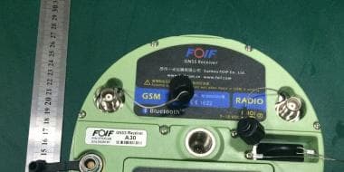
2AD3SA30
Feb 01, 2015GNSS Receiver
Equipment Class
DXT - Part 15 Low Power Transceiver, Rx Verified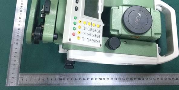
2AD3SRTS102
Feb 01, 2015Total Station
Equipment Class
DXT - Part 15 Low Power Transceiver, Rx Verified