2AD66-RF2401F202.4G RF module with amplifier
NiceRF Wireless Technology LTD.Application Details
- Equipment Class
- DXT - Part 15 Low Power Transceiver, Rx Verified
- Date of Grant
- Feb 11, 2015
- Application Purpose
- Original Equipment
- Date of Application
- Feb 11, 2015
- Equipment Note
- 2.4G RF module with amplifier
- Frequency Range
- 2402.00000000 - 2480.00000000
- Country
- China
Documents & Files
Document Text
Text extracted from the exhibit documents filed with the FCC. Open a document above to read the original.
Users Manual
2.4G RF24L01F20 TEL:0755-61596687FAX:0755-27838582www.nicerf.com第 1 页共 5 页 RF24L01F20 1.Description RF24L01F20Moduleisahighintegratedwirelessmodule, whichworkedin2.4GHzofISMband.RF24L01F20adopts Nordic’sRFchipnRF24L01+andhighefficiencyRFamplifier. Thefeatureofhighdatarate(maximum2Mbps),goodsensitivity ( -102dBm ) butlowharmonic andlowunexpected radiation extendtherangeandimprovethe linkperformance. 2.Features FrequencyRange: Maximumpoweroutput:20dBm Sensitivityupto:-102dBm@250Kpbs Datarate:250K,1Mpbs,2Mpbs GFSKModulation, FIFO:32bytes Ultralowpoweroffmode Supportfunctionsoffrequencyhopping Internalintegratedvoltageregulator operatingvoltagerange:1.9-3.6V operatingtemperaturerange:-40~+85°C 3.Application Wirelessremotecontrol Remotemeterreading SmartHome Personaldatarecords Toycontrol TirePressureMonitoring healthmonitoring Tagreader 2.4G RF module with amplifier 2400-2480MHZ RF24L01F20 TEL:0755-61596687FAX:0755-27838582www.nicerf.com第 2 页共 5 页 4.Schematic 5.ElectricalCharacteristics ★Belowparametersismeasuredat3V. ParameterMin.Type.Max.UnitConditions Operationconditions Operatingvoltagerange1.93.33.6V Operatingtemperaturerange-4085°C Currentconsumption RXCurrent23.524mA TXCurrent135150mA@20dBm SleepCurrent<1uA RFparameters Frequencyrange24002525MHZ Modulationrate2502000KbpsGFSK Outputpowerrange420dBmPower0=5dBm,3=20dBm Maximumoutputpower18.520dBm RXsensitivity-100-102dBm@data=250kbps RF24L01F20 TEL:0755-61596687FAX:0755-27838582www.nicerf.com第 3 页共 5 页 6.Typicalapplicationcircuit 7.PinsConfiguration PinNo.PinDefinitionsDescription 1 VCCConnecttoVCC(1.9-3.6V) 2 GNDConnecttoground 3 CEChipenable 4 CSNCSNofSPIinterface 5 SCKSCKorSPIinterface 6 MOSIMOSIofSPIinterface 7 MISOMISOofSPIinterface 8 IRQInterruptoutput,activelow 9 ANTConnect50ohmcoaxialantenna 10 GNDConnecttoground 11 GNDConnecttoground RF24L01F20 TEL:0755-61596687FAX:0755-27838582www.nicerf.com第 4 页共 5 页 8.MechanicalDimension: Appendix: ThemoduleisequippedwithastandardDEMOboardforcustomertodebugtheprogramandtestdistance. Itshowsasbelow: RF24L01F20 TEL:0755-61596687FAX:0755-27838582www.nicerf.com第 5 页共 5 页 TheLCDFullSegmentisasbelow: UserscansettheparametersoftheRFmodulesuchasworkingmode/frequency/transmitterpower/transmission dataratethroughthebuttons,andmeasurethewirelesscommunicationdistance. WorkingMode 1)MasterMode:Send1packetpersecond,andwaitingfortheacknowledge; 2)SlaveMode:StayinRxmodetowaitforthedatafromthemaster,itwillsendbacktheacknowledgedsignalafter receivedthedatafromthemaster. 3)TxTestMode:RFmodulecontinuouslytransmitsignal; 4)RxTestMode:RFmoduleisalwaysinRxmode; 5)StandbyMode:RFmoduleisalwaysinstandbystate. ButtonOperation 1)[SET]Button Pressthe[SET]buttontoenterintosettingmode;Orpressthe[SET]buttontobeoutofthesettingmodeupon thelastparameterisdone. 2)[UP/Down]Button Insettingmode,pressthe[UP/Down]buttontoincrease/decreasethevalueofflashicon. Note:TheDEMOboardhasFLASHmemoryinside,allthesettingparameterswillbesavedautomaticallyandkeep unchangedevenpower-off. Note: The antenna(s) used for this transmitter must not be co-located or operating in conjunction with any other Only those antenna(s) tested with the device or similar antenna(s) with equal or lesser gain may be used with this transmitter antenna or transmitter The RF2401F20 module is designed to comply with the FCC statement. FCC ID is 2AD66-RF2401F20. The host system using RF2401F20, should have label indicated it contain modular’s FCC ID 2AD66-RF2401F20 FCC Information and Copyright This equipment has been tested and found to comply with the limits for a Class B digital device, pursuant to part 15 of the FCC Rules. These limits are designed to provide reasonable protection against harmful interference in a residential installation. This equipment generates, uses and can radiate radio frequency energy and, if not installed and used in accordance with the instructions, may cause harmful interference to radio communications. However, there is no guarantee that interference will not occur in a particular installation. If this equipment does cause harmful interference to radio or television reception, which can be determined by turning the equipment off and on, the user is encouraged to try to correct the interference by one or more of the following measures: —Reorient or relocate the receiving antenna. —Increase the separation between the equipment and receiver. —Connect the equipment into an outlet on a circuit different from that to which the receiver is connected. —Consult the dealer or an experienced radio/TV technician for help. 15.19 Labelling requirements. This device complies with part 15 of the FCC Rules. Operation is subject to the following two conditions: (1)This device may not cause harmful interference, and (2) this device must accept any interference received, including interference that may cause undesired operation. changes or modifications not expressly approved by the party responsible for compliance could void the user's authority to operate the equipment.
Cover Letter(s)
SCS-F18: Project and Product Certification Representative Authorization Letter Page 1 of 2 Rev 5.0 775 Montague Expressway Milpitas, CA 95035 Tel: 408-526-1188 Fax: 408-526-1088 Email: [email protected] Project and Product Certification Representative Authorization Letter Reason for Amendment (current / obsolete) Revision History Approved Date From To Initial Release (obsolete) 1.0 1.0 Nov-14-2006 Revised wording (obsolete) 1.0 2.0 Sept–25-2007 Updated company template (obsolete) 2.0 3.0 Jan-31-2012 Updated letter information (obsolete) 3.0 4.0 May-23-2014 Added FCC ID field (current) 4.0 5.0 Sept 16 2014 SCS-F18: Project and Product Certification Representative Authorization Letter Page 2 of 2 Rev 5.0 NiceRF Wireless Technology LTD. 2015/02/03 To: SIEMIC, INC. 775 Montague Expressway, Milpitas, CA 95035 USA Dear Sir/Madam, Re: Product Certification Representative Authorization Letter We, __ NiceRF Wireless Technology LTD. _ _hereby authorize SIEMIC, Inc. to act as a Certification Body for certifying for the following project(s): Product: 2.4G RF module with amplifier Trade Name: N/A Model Name: RF2401F20 Serial Model: N/A FCC ID: 2AD66-RF2401F20 Sincerely, Client’s signature Client’s name / title GH.Song Manager Contact information / address 4th floor of DuoTai Building, Anle Industrial Zone, Area 43, Baoan Dist, Shenzhen, China
Cover Letter(s)
SCS-F19: Confidentiality Request Letter Page 1 of 2 Rev 3.0 775 Montague Expressway Milpitas, CA 95035 Tel: 408-526-1188 Fax: 408-526-1088 Email: [email protected] Confidentiality Request Letter Reason for Amendment (current / obsolete) Revision History Approved Date From To Initial Release (obsolete) 1.0 1.0 Nov-14-2006 Adding CFR 2.459 (obsolete) 1.0 2.0 August – 11 - 2008 Updated company template & Added text box (current) 2.0 3.0 Jan-31-2012 SCS-F19: Confidentiality Request Letter Page 2 of 2 Rev 3.0 NiceRF Wireless Technology LTD. 2015-02-03 To: Federal Communications Commission Authorization and Evaluation Division 7435 Oakland Mills Road Columbia, MD Subject: Permanent Confidentiality Request for FCC ID: 2AD66-RF2401F20 We hereby request confidential treatment of information accompanying this application as outlined below: - Block Diagram - Schematics - Operational Description The above materials contain trade secrets and proprietary information not customarily released to the public. The public disclosure of these materials may be harmful to the applicant and provide unjustified benefits to its competitors. The applicant understands that pursuant to Section 0.457 & 0.459 of the Rules, disclosure of this application and all accompanying documentation will not be made before the date of the Grant for this application. Sincerely, Client’s signature Client’s name / title GH.Song Manager Contact information / address 4th floor of DuoTai Building, Anle Industrial Zone, Area 43, Baoan Dist, Shenzhen, China
Cover Letter(s)
SCS-F26 Modular Approval Letter Page 1 of 2 Rev 7.0 775 Montague Expressway Milpitas, CA 95035 Tel: 408-526-1188 Fax: 408-526-1088 Email: [email protected] Modular Approval Declaration Letter Reason for Amendment (current / obsolete) Revision History Approved Date From To Initial Release (Obsolete) 1.0 1.0 Dec-04-2006 Added IC Modular Letter (Obsolete) 1.0 2.0 Feb 16 2009 Add LMA and MA option (Obsolete) 2.0 3.0 April 14 2010 Revised per RSS Gen issue 3.0 (Obsolete) 3.0 4.0 Jan 12 2011 Removed Foot(2) (obsolete) 4.0 5.0 July 19 2011 Adding New note per KDB996369 D01 V01R03 (obsolete) 5.0 6.0 August 29 2011 Updated company template & Added text box (current) 6.0 7.0 Jan-31-2012 SCS-F26 Modular Approval Letter Page 2 of 2 Rev 7.0 NiceRF Wireless Technology LTD. (Date) 2015-02-03 (wifi module) FCC ID : 2AD66-RF2401F20 , is seeking FCC Authorization as a Single Modular transmitter / Single Limited Modular Approval (Please check one). The EUT meets the requirements for Single Modular approval / Single Limited Modular Approval (please check one) as detailed in FCC public Notice DA00-1407. Compliance to each of the requirements is described below : Questions are: * Please provide a detailed explanation if the answer is “No.” 1. “The modular transmitter must have its own RF shielding.” Yes / No 2. “The modular transmitter must have buffered modulation/data inputs.” Yes / No 3. “The modular transmitter must have its own power supply regulation.” Yes / No 4. “The modular transmitter must comply with the antenna requirements of section 15.203 and 15.204(c).” Yes / No 5. “The modular transmitter must be tested in a stand-alone configuration.” Yes / No 6. “The modular transmitter must be labeled with its own FCC ID number.” Yes / No 7. “The modular transmitter must comply with any specific rule or operating requirements applicable to the transmitter and the manufacture must provide adequate instruction along with the module to explain any such requirements.” Yes / No 8. “The modular transmitter must comply with any applicable RF exposure requirements.” Yes / No Note: (1) LMA may be granted when one or more of the requirements in the table above cannot be demonstrated. LMA will also be issued in those instances where applicants can demonstrate that they will retain control over the final installation of the device, such that compliance of the end product is assured. In such cases, an operating condition on the LMA for the module must state that the module is only approved for use when installed in devices produced by a specific manufacturer. When LMA is sought, the application for equipment certification must specifically state how control of the end product into which the module will be installed, and will be maintained, such that full compliance of the end product is always ensured. (2) Please provide Clear and specific instructions describing the conditions, limitations and procedures for third-parties to use and/or integrate the module into a host device. (3) For non-Software Defined Radio transmitter modules where software is used to ensure compliance of the device, technical description of how such control is implemented to ensure prevention of third party modification must be provided (see KDB 594280). Note 1: Compliance of a module in its final configuration is the responsibility of the applicant. A host device will not be considered certified if the instructions regarding antenna configuration provided in the original description, of one or more separately certified modules it contains, were not followed. Example: A separately certified low-power transceiver module using Bluetooth technology which is housed in a desktop computer, laptop or peripheral does not require the overall system to be recertified, if the desktop computer, laptop or peripheral, as a stand-alone unit, complies with all applicable technical standards. Client’s signature Client’s name / title GH.Song Manager Contact information / address 4th floor of DuoTai Building, Anle Industrial Zone, Area 43, Baoan Dist, Shenzhen, China
External Photos
APPENDIX-PHOTOGRAPHS OF EUT CONSTRUCTIONAL DETAILS Photo 1 Photo 2 Antenna
ID Label/Location Info
FCC ID LABELING AND LOCATION FCC ID Label 2.4G RF module with amplifier Model NO.: RF2401F20 FCC ID: 2AD66-RF2401F20 FCC ID Label Location The label shown shall be permanently affixed at a conspicuous location on the device and be readily visible to the user at the time purchase (Labeling requirements per 2.925)
Internal Photos
APPENDIX-PHOTOGRAPHS OF EUT CONSTRUCTIONAL DETAILS Photo 1 Photo 2
Test Report
FCC RADIO TEST REPORT FCC ID: 2AD66-RF2401F20 Product: 2.4G RF module with amplifier Trade Name: N/A Model Name: RF2401F20 Serial Model: N/A Report No.: NTEK- 2014NT12042151F Prepared for NiceRF Wireless Technology LTD. 4th floor of DuoTai Building, Anle Industrial Zone, Area 43, Baoan Dist, Shenzhen, China Prepared by Shenzhen NTEK Testing Technology Co., Ltd. 1/F, Building E, Fenda Science Park, Sanwei Community,Xixiang Street Bao’an District, Shenzhen P.R. China Tel.: +86-0755-61156588 Fax.: +86-0755-61156599 Website:www.ntek.org.cn Page 2 of 60 Report No.: NTEK-2014NT12042151F ` TEST RESULT CERTIFICATION Applicant’s name ................. : NiceRF Wireless Technology LTD. Address ................................. : 4th floor of DuoTai Building, Anle Industrial Zone, Area 43, Baoan Dist, Shenzhen, China Manufacture's Name ............ : NiceRF Wireless Technology LTD. Address ................................. : 4th floor of DuoTai Building, Anle Industrial Zone, Area 43, Baoan Dist, Shenzhen, China Product description Product name ........................... : 2.4G RF module with amplifier Model and/or type reference : RF2401F20 Serial Model: N/A Rating(s) ................................ : DC 5.0V Standards ............................. : FCC Part15.249 01 Oct. 2014 Test procedure ..............................ANSI C63.4-2003 This device described above has been tested by NTEK, and the test results show that the equipment under test (EUT) is in compliance with the FCC requirements. And it is applicable only to the tested sample identified in the report. This report shall not be reproduced except in full, without the written approval of NTEK, this document may be altered or revised by NTEK, personal only, and shall be noted in the revision of the document. Date of Test ............................................ : Date (s) of performance of tests ............. : 04 Dec. 2014 ~28 Jan. 2015 Date of Issue ........................................... : 28 Jan. 2015 Test Result ............................................... : Pass Testing Engineer : Denny Huang Technical Manager : (Brown Lu) Authorized Signatory : (Bill Yao) Page 3 of 60 Report No.: NTEK-2014NT12042151F ` Table of Contents Page 1 . SUMMARY OF TEST RESULTS 4 1.1 TEST FACILITY 5 1.2 MEASUREMENT UNCERTAINTY 5 2 . GENERAL INFORMATION 6 2.1 GENERAL DESCRIPTION OF EUT 6 2.2 DESCRIPTION OF TEST MODES 8 2.3 BLOCK DIGRAM SHOWING THE CONFIGURATION OF SYSTEM TESTED 9 2.4 DESCRIPTION OF SUPPORT UNITS(CONDUCTED MODE) 10 2.5 EQUIPMENTS LIST FOR ALL TEST ITEMS 11 3 . ANTENNA REQUIREMENT 12 3.1 STANDARD REQUIREMENT 12 3.2 EUT ANTENNA 12 3.3 CONDUCTED EMISSION MEASUREMENT 13 3.3.1 POWER LINE CONDUCTED EMISSION LIMITS 13 3.3.2 TEST PROCEDURE 14 3.3.3 DEVIATION FROM TEST STANDARD 14 3.3.4 TEST SETUP 14 3.2.5 TEST RESULT 15 3.4 RADIATED EMISSION MEASUREMENT 16 3.4.1 RADIATED EMISSION LIMITS 16 3.4.2 TEST PROCEDURE 17 3.4.3 DEVIATION FROM TEST STANDARD 17 3.4.4 TEST SETUP 18 3.4.5 TEST RESULTS (BLOW 30MHZ) 20 3.4.6 TEST RESULTS (BETWEEN 30 – 1000 MHZ) 21 3.4.7 TEST RESULTS (ABOVE 1000 MHZ) 23 3.4.8 TEST RESULTS (RESTRICTED BANDS REQUIREMENTS) 41 4 . BANDWIDTH TEST 53 4.1 TEST PROCEDURE 53 4.2 DEVIATION FROM STANDARD 53 4.3 TEST SETUP 53 4.4 TEST RESULTS 54 5 . EUT TEST PHOTO 60 APPENDIX-PHOTOGRAPHS OF EUT CONSTRUCTIONAL DETAILS Page 4 of 60 Report No.: NTEK-2014NT12042151F ` 1. SUMMARY OF TEST RESULTS Test procedures according to the technical standards: FCC Part15, Subpart C (15.249) Standard Section Test Item Judgment Remark 15.207 Conducted Emission N/A 15.203 Antenna Requirement Pass 15.249 Radiated Spurious Emission Pass 15.205 Band Edge Emission Pass 15.249 Occupied Bandwidth Pass Page 5 of 60 Report No.: NTEK-2014NT12042151F ` 1.1 TEST FACILITY NTEK Testing Technology Co., Ltd Add. : 1/F, Building E, Fenda Science Park, Sanwei Community, Xixiang Street, Bao’an District, Shenzhen P.R. China. FCC FRN Registration No.:238937; IC Registration No.:9270A-1 CNAS Registration No.:L5516 1.2 MEASUREMENT UNCERTAINTY The reported uncertainty of measurement y ± U,where expended uncertainty U is based on a standard uncertainty multiplied by a coverage factor of k=2,providing a level of confidence of approximately 95 %。 No. Item Uncertainty 1 Conducted Emission Test ±1.38dB 2 RF power,conducted ±0.16dB 3 Spurious emissions,conducted ±0.21dB 4 All emissions,radiated(<1G) ±4.68dB 5 All emissions,radiated(>1G) ±4.89dB 6 Temperature ±0.5°C 7 Humidity ±2% Page 6 of 60 Report No.: NTEK-2014NT12042151F ` 2. GENERAL INFORMATION 2.1 GENERAL DESCRIPTION OF EUT Equipment 2.4G RF module with amplifier Trade Name N/A Model Name RF2401F20 Serial Model N/A Model Difference N/A Product Description The EUT is a 2.4G RF module with amplifie r. Operation Frequency: 2402MHz-2480MHz Modulation Type: GFSK Bit Rate of Transmitter 250Kbps/1Mbps/2Mbps Antenna Designation: Wire Antenna Antenna Gain(Peak) 1.0 dBi EIRP 105.08dBuv/m@3m Based on the application, features, or specification exhibited in User's Manual, the EUT is considered as an ITE/Computing Device. More details of EUT technical specification, please refer to the User's Manual. Channel List Please refer to the Note 2. Adapter N/A Battery N/A Power Supply DC 5.0V Note: 1. For a more detailed features description, please refer to the manufacturer’s specifications or the User's Manual. Page 7 of 60 Report No.: NTEK-2014NT12042151F ` 2. Channel List Channel Frequency (MHz) Channel Frequency (MHz) Channel Frequency (MHz) 00 2402 27 2429 54 2456 01 2403 28 2430 55 2457 02 2404 29 2431 56 2458 03 2405 30 2432 57 2459 04 2406 31 2433 58 2460 05 2407 32 2434 59 2461 06 2408 33 2435 60 2462 07 2409 34 2436 61 2463 08 2410 35 2437 62 2464 09 2411 36 2438 63 2465 10 2412 37 2439 64 2466 11 2413 38 2440 65 2467 12 2414 39 2441 66 2468 13 2415 40 2442 67 2469 14 2416 41 2443 68 2470 15 2417 42 2444 69 2471 16 2418 43 2445 70 2472 17 2419 44 2446 71 2473 18 2420 45 2447 72 2474 19 2421 46 2448 73 2475 20 242…
Text truncated - open the document above for the full version.
Test Setup Photos
Page 60 of 60 Report No.: NTEK-2014NT12042151F ` 5. EUT TEST PHOTO Radiated Measurement Photos
Contact Information
Applicant
GH. Song
Test Firm
Shenzhen NTEK Testing Technology Co., Ltd.Jason Chen
Technical Specifications
| # | Rule Parts | Frequency Range | Power Output |
|---|---|---|---|
| 1 | 15C | 2.40 GHz - 2.48 GHz | - |
Other Applications from NiceRF Wireless Technology LTD.
2AD66-DMR818SU
Sep 20, 2026Wireless walkie-talkie module
Equipment Class
TNB - Licensed Non-Broadcast Station Transmitter2AD66-LORA1281F27-T
Sep 20, 20262.4GHz LoRa Wireless Transceiver Module
Equipment Class
DTS - Digital Transmission System2AD66-LORA1276-915
Mar 27, 2024Wireless Module with LoRa
Equipment Class
DTS - Digital Transmission System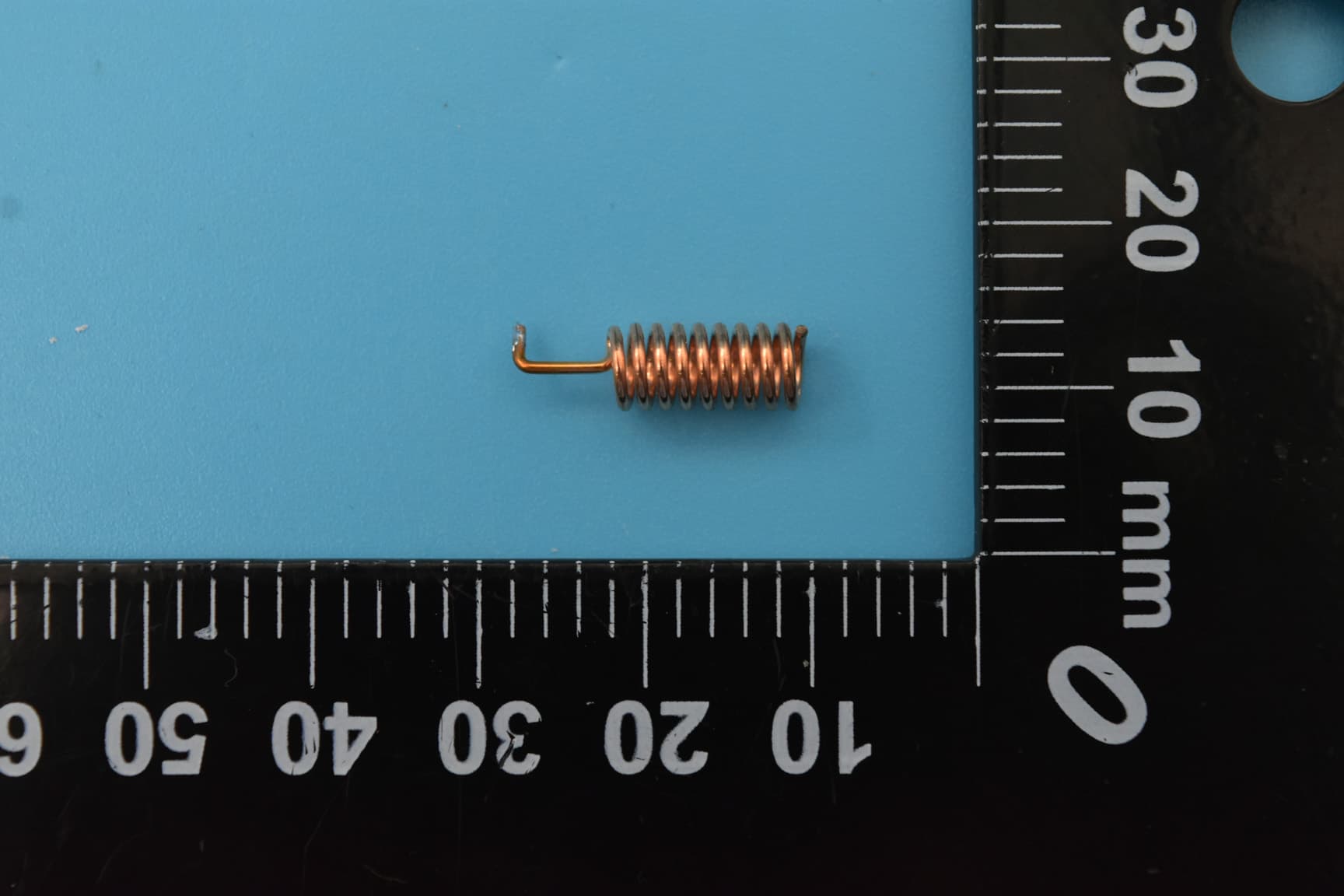
2AD66-CC68-C1
Aug 03, 2022LoRa Wireless Module
Equipment Class
DTS - Digital Transmission System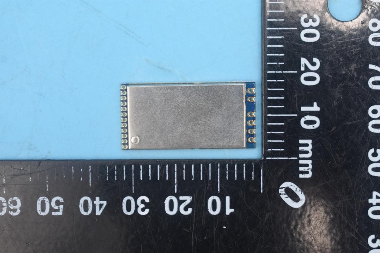
2AD66-LORA128XF27
Jul 06, 2020Wireless Module
Equipment Class
DTS - Digital Transmission System