2AD9E-BTMBTM rev3
JL Audio, Inc.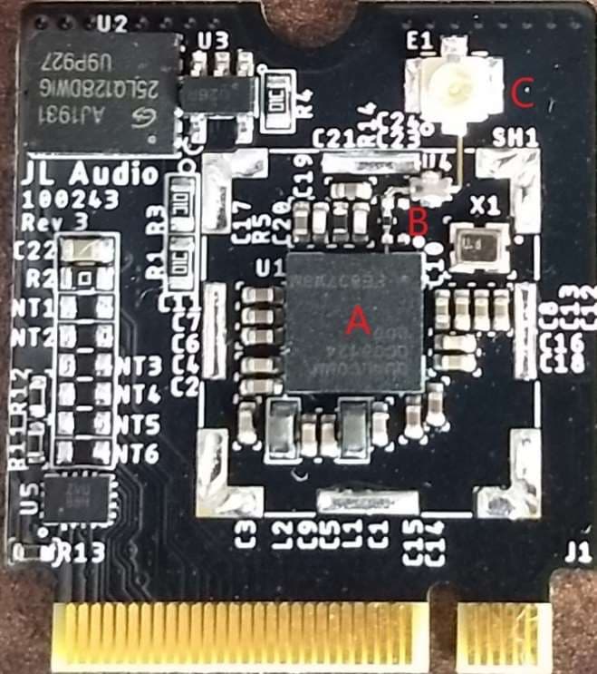
Click to zoom
Application Details
- Equipment Class
- DTS - Digital Transmission System
- Date of Grant
- Feb 08, 2021
- Application Purpose
- Original Equipment
- Date of Application
- Feb 08, 2021
- Equipment Note
- BTM rev3
- Frequency Range
- 2402.00000000 - 2480.00000000
- Company
- JL Audio, Inc.
- Country
- United States
Documents & Files
Document Text
Text extracted from the exhibit documents filed with the FCC. Open a document above to read the original.
Users Manual
Date: 25 January 2021 FCC MODULAR INTEGRATION INSTRUCTIONS | FCC ID: 2AD9E-BTM JL Audio QCC5124 Module FCC ID: 2AD9E-BTM IC: 25930-BTM 1.0 INTRODUCTION The purpose of this document is to provide guidance on certifying a modular transmitter (module) and the key elements to be reviewed by a Telecommunication Certification Body (TCB) during the certification process. This guidance includes: • the integration instructions to be provided by a grantee (applicant) to a host manufacturer; • a list of key elements to be reviewed by a TCB during the certification process; and • guidance for grant comments to be included on the grant of certification. 2.0 INTEGRATION INSTRUCTIONS 2.1 General Sections 2.2 through 2.10 describe the items that must be provided in the integration instructions for host product manufacturers to use when integrating a module in a host product. 2.2 List of applicable FCC rules JL Audio, Model Number, FCC ID: 2AD9E-BTM is seeking modular approval. The radio meets the requirements for modular approval as detailed in FCC 15.247, RSS-247. Compliance to each of the requirements is described below: Frequency Hopping – BT Classic and EDR This device can operate as a Frequency Hopping Spread Spectrum Device (FHSS) The frequency range is 2402 MHz to 2483.5 MHz. Hopping frequencies are separated by 1MHz within 20dB. There are 79 hopping frequencies. Frequency slots are selected by a pseudo-random sequence and each slot is used, on average, an equal amount. Slots are used for 625 microseconds and the specification allows for multi-slot packets up to five slots in length before hopping again. The longest occupancy of a single channel is thus 3.125 milliseconds. The sequence is seeded by the Bluetooth clock and the Bluetooth BD_Address, a unique ID on a unit-by-unit basis. This unit cannot coordinate with other FHSS units. DTS – Direct Sequence Spread Spectrum – BT Low Energy This device can also operate as a DTS device. The frequency range is the same as in FHSS mode. BT LE has forty 2MHz channels. Data is transmitted using Gaussian frequency shift modulation. The device advertises on channels 37 (2402 MHZ), 38 (2426 MHz), and 39 (2480 MHz). The other channels are available for the remainder of data transmission purposes. The device advertises alternating between the three advertising channels. The device exchanges a channel map with its partner, and they select their preferred channel for further communications. A new channel is selected with each pairing event. FCC Part 15 Compliance Statement This device complies with part 15 of the FCC Rules. Operation is subject to the following two conditions: (1) This device may not cause harmful interference, and (2) this device must accept any interference received, including interference that may cause undesired operation. 2.3 Summarize the specific operational use conditions Device Antenna Module shall be used with one of the following pre-certified antennas: Yageo, ANTX100P001B24003, 4.4dBi, Trace Yageo, ANTX100P112B24553, 2.2dBi, Patch Yageo, ANTX100P011B24003, 2.2dBi, Trace Attachment of any higher-gain antenna or other-patterned antenna is not permitted. Increases in the shielded length of the antenna which do not increase its gain or change its emission pattern are permitted. Modification of the module to install an antenna not approved for use voids the user’s authority to operate the equipment. Co-Location This device and its antenna must not be co-located or operated in conjunction with another transmitter or antenna without the use of FCC multi-product procedures. Bluetooth Radio The Bluetooth radio is driven from the QCC5124. The signal path contains a matching network, bandpass filter, and mini coaxial connector before it reaches the antenna. The radio complies with the Bluetooth 5 standard for Bluetooth Classic and Bluetooth Low Energy. Table 1: Bluetooth Classic standard EDR 3M EDR 2M BR Modulation Scheme 8DPSK π/4 DQPSK GFSK Max Data Rate 3Mbps 2Mbps 1Mbps This radio complies with FCC parts 15.247. The firmware provided by Qualcomm manages the transmitter. 2.4 Limited module procedures Not applicable to current module design 2.5 Trace antenna designs Not applicable to current module design 2.6 RF exposure considerations • For the FCC, the radio module will be authorized for mobile use without restriction. • Distance from user during product use is greater than 20cm • For ISED Canada, the antenna must be no closer than 20cm from the user. • Test Report documenting output power: RSS-247:2017 2.7 Antennas Module shall be used with one of the following pre-certified antennas: Yageo, ANTX100P001B24003, 4.4dBi, Trace Yageo, ANTX100P112B24553, 2.2dBi, Patch Yageo, ANTX100P011B24003, 2.2dBi, Trace Attachment of any higher-gain antenna or other-patterned antenna is not permitted. Increases in the shielded length of the antenna which do not increase its gain or change its emission pattern are permitted. Modification of the module to install an antenna not approved for use voids the user’s authority to operate the equipment. Antenna Placement Instructions Antenna shall be separated from the user by a minimum distance of 20cm, such that the operation separation distance shall exceed the test separation distance. Any additional spacing serves to minimize the user’s exposure to RF emissions, and will increase the Bluetooth link quality between the source and sink devices when the device is paired. 2.8 Label and compliance information The Module must be labeled with the following: “FCC ID: 2AD9E-BTM” The end product (Host + Module) must be labeled with the following: “Contains FCC ID: 2AD9E-BTM” The Part 15 statement printed within this manual should also be included in the Product’s manual, after the device passes Part 15B unintentional radiator testing as indicated previously. 2.9 Information on test modes and additional testing requirements5 Bluetooth Radio The Bluetooth radio is driven from the QCC5124. The signal path contains a matchin…
Text truncated - open the document above for the full version.
Users Manual
Date: 22 January 2021 USER MANUAL | FCC ID: 2AD9E-BTM JL Audio QCC5124 Module FCC ID: 2AD9E-BTM IC: 25930-BTM FCC Part 15 Compliance Statement This device complies with part 15 of the FCC Rules. Operation is subject to the following two conditions: (1) This device may not cause harmful interference, and (2) this device must accept any interference received, including interference that may cause undesired operation. JL Audio, Model Number, FCC ID: 2AD9E-BTM is seeking modular approval. The radio meets the requirements for modular approval as detailed in FCC 15.247. Compliance to each of the requirements is described below: 1. “The modular transmitter must have its own RF shielding.” The radio portion of the module is contained in its own RF shielding. The shielding is installed at the factory. Please see the Internal Photos exhibit. 2. “The modular transmitter must have buffered modulation/data inputs.” The EUT has buffered data inputs to insure compliance with Part 15 requirements under conditions of excessive data rates or over-modulation. Please see the Schematics exhibit. 3. “The modular transmitter must have its own power supply regulation.” The EUT has its own power supply regulation to insure compliance with Part 15 requirements regardless of the quality or level of external DC supplying the module from the host unit. Please see Schematics exhibit. Also, the technical report exhibit contains AC power line conducted emissions data taken with the EUT powered from a linear power supply that contains no EMC suppression components. 4. “The modular transmitter must comply with the antenna requirements of Section 15.203 and 15.204(c).” The EUT meets the FCC antenna requirements. Please see Antenna information exhibit and internal photos exhibit. 5. “The modular transmitter must be tested in a stand-alone configuration.” The EUT was tested in a stand-alone configuration. The module was greater than 10 cm from the host device. Please see test setup photos exhibit and technical report exhibit. 6. “The modular transmitter must be labeled with its own FCC ID number.” The EUT is labeled with its own FCC ID number. Please see FCC ID label & location exhibit. If the FCC ID number will not be visible when the module is installed inside a host device, another label with the FCC ID will be applied to the exterior of the host device. 7. “The modular transmitter must comply with any specific rule or operating requirements applicable to the transmitter and the manufacturer must provide adequate instructions along with the module to explain any such requirements.” The EUT is compliant with all applicable FCC rules. Detail instructions for maintaining compliance are given in the User Manual. 8. “The modular transmitter must comply with any applicable RF exposure requirements.” The EUT is compliant with all applicable RF exposure requirements. Please see RF Exposure Exhibit. Changes to the Device Changes or modifications not expressly approved by the manufacturer could void the user’s authority to operate the equipment. Device Antenna Module shall be used with one of the following pre-certified antennas: Yageo, ANTX100P001B24003, 4.4dBi, Trace Yageo, ANTX100P112B24553, 2.2dBi, Patch Yageo, ANTX100P011B24003, 2.2dBi, Trace Attachment of any higher-gain antenna or other-patterned antenna is not permitted. Increases in the shielded length of the antenna which do not increase its gain or change its emission pattern are permitted. Modification of the module to install an antenna not approved for use voids the user’s authority to operate the equipment. Co-Location This device and its antenna must not be co-located or operated in conjunction with another transmitter or antenna. Digital Device Integration This equipment has been tested and found to comply with the limits for a Class B digital device, pursuant to part 15 of the FCC Rules. These limits are designed to provide reasonable protection against harmful interference in a residential installation. This equipment generates, uses and can radiate radio frequency energy and, if not installed and used in accordance with the instructions, may cause harmful interference to radio communications. However, there is no guarantee that interference will not occur in a particular installation. If this equipment does cause harmful interference to radio or television reception, which can be determined by turning the equipment off and on, the user is encouraged to try to correct the interference by one or more of the following measures: - Reorient or relocate the receiving antenna. - Increase the separation between the equipment and receiver. - Connect the equipment into an outlet on a circuit different from that to which the receiver is connected. - Consult the dealer or an experienced radio/TV technician for help. Integration of this product into an end-device with various host modules will require re-testing for Digital Device emissions compliance, as data lines from the module are connectable to host devices. Compliance should be feasible and any failures in compliance will require adjustments to the host device to resolve. Even when the host device does not have any oscillators or logic on board which would independently trigger Digital Device requirements, digital device testing for the product will be necessary due to those parts on the module. Integration Instructions - Availability to Host Manufacturers This module is intended for use in products designed in whole or in part by JL Audio (JLA), and is not approved for use in third party hosts. As such, JLA retains responsibility for ensuring compliance with intentional and unintentional radiator requirements. Host product design shall comply with best design practices, especially with respect to grounding and routing of digital lines, to minimize unintentional emissions. Antenna Placement Instructions Antenna shall be separated from the user by a minimum distance of 20cm, such that the operation separation distance…
Text truncated - open the document above for the full version.
Cover Letter(s)
Date: 10 March 2020 Federal Communications Commission Authorization and Evaluation Decision 7435 Oakland Mills Road Columbia, Maryland 21046 RE: Cover Letter for FCC Application FCC ID: 2AD9E-BTM We hereby request FCC single modular certification under rule part 15.247 for “JL Audio BT Module”. This device contains a Bluetooth 5 radio transmitter. The Bluetooth radio has been tested for intentional radiation by Element Materials Technology, and the unit has been tested for unintentional radiation at the same facility. Sincerely, Leah Sorensen Technical Program Manager – JL Audio, Inc.
Cover Letter(s)
Date: 10 March 2020 To whom it may concern, We, the undersigned, hereby authorize Leah Sorensen to act on our behalf, as our agent, in the following matters related to the FCC and/or Industry Canada approval of our products: report submittal, related correspondence, the signing of all documents relating to these matters, and any other lawful activity necessary to obtain such certification. Any act carried out by Leah Sorensen within the scope of this authorization shall have the same affect as our own. This authorization shall expire 12 months from original date. Sincerely, Stephen Leigh Ph.D. Vice President Electronic Engineering
Cover Letter(s)
Date: 10 March 2020 Dear Application Examiner: JL Audio, Model Number, FCC ID: 2AD9E-BTM is seeking modular approval. The radio meets the requirements for modular approval as detailed in FCC 15.212. Compliance to each of the requirements is described below: 1. “The modular transmitter must have its own RF shielding.” The radio portion of the module is contained in its own RF shielding. The shielding is installed at the factory. Please see the Internal Photos exhibit. 2. “The modular transmitter must have buffered modulation/data inputs.” The EUT has buffered data inputs to insure compliance with Part 15 requirements under conditions of excessive data rates or over-modulation. Please see the Schematics exhibit. 3. “The modular transmitter must have its own power supply regulation.” The EUT has its own power supply regulation to insure compliance with Part 15 requirements regardless of the quality or level of external DC supplying the module from the host unit. Please see Schematics exhibit. Also, the technical report exhibit contains AC power line conducted emissions data taken with the EUT powered from a linear power supply that contains no EMC suppression components. 4. “The modular transmitter must comply with the antenna requirements of Section 15.203 and 15.204(c).” The EUT meets the FCC antenna requirements. Please see Antenna information exhibit and internal photos exhibit. 5. “The modular transmitter must be tested in a stand-alone configuration.” The EUT was tested in a stand-alone configuration. The module was greater than 10 cm from the host device. Please see test setup photos exhibit and technical report exhibit. 6. “The modular transmitter must be labeled with its own FCC ID number.” The EUT is labeled with its own FCC ID number. Please see FCC ID label & location exhibit. If the FCC ID number will not be visible when the module is installed inside a host device, another label with the FCC ID will be applied to the exterior of the host device. 7. “The modular transmitter must comply with any specific rule or operating requirements applicable to the transmitter and the manufacturer must provide adequate instructions along with the module to explain any such requirements.” The EUT is compliant with all applicable FCC rules. Detail instructions for maintaining compliance are given in the User Manual. 8. “The modular transmitter must comply with any applicable RF exposure requirements.” The EUT is compliant with all applicable RF exposure requirements. Please see RF Exposure Exhibit. Please contact me if you have additional questions. Your attention to this matter is greatly appreciated. Best regards, Leah Sorensen Technical Program Manager – JL Audio, Inc.
Cover Letter(s)
Date: 10 March 2020 Federal Communications Commission Authorization and Evaluation Division 7435 Oakland Mills Road Columbia, Maryland 21046 Re: Request for confidentiality FCC ID: 2AD9E-BTM To whom it may concern, We hereby respectfully request that under the provision of 47 CFR 0.459 and 0.457(d) the documents listed below and attached with this application for certification be provided with confidential status. Type of Confidentiality Requested Exhibit Short Term Permanent Block Diagrams Short Term Permanent Internal Photos Short Term Permanent Operation Description/Theory of Operation Short Term Permanent Schematics Short Term Permanent User’s Manual Any exhibit / information for which we have requested confidentiality, but which may not be accorded such treatment by the FCC, should be returned to us. The documents listed above contain trade secrets that are treated as confidential by us. Substantial competitive harm to us could result should they be made available to the public. Sincerely, Leah Sorensen Technical Program Manager – JL Audio, Inc.
External Photos
Date: 10 March 2020 INTERNAL PHOTOS | FCC ID: 2AD9E-BTM TOP SIDE, WITH SHIELD BOTTOM SIDE INTERNAL PHOTOS | FCC ID: 2AD9E-BTM TOP SIDE, WITHOUT SHIELD A. QCC5124 BT MCU B. BT matching network and 2.4 GHz bandpass filter C. U. FL Mini-Coaxial antenna connector
ID Label/Location Info
Date: 11 November, 2020 LABEL AND LOCATION | FCC ID: 2AD9E-BTM
Internal Photos
Date: 10 March 2020 INTERNAL PHOTOS | FCC ID: 2AD9E-BTM TOP SIDE, WITH SHIELD BOTTOM SIDE INTERNAL PHOTOS | FCC ID: 2AD9E-BTM TOP SIDE, WITHOUT SHIELD A. QCC5124 BT MCU B. BT matching network and 2.4 GHz bandpass filter C. U. FL Mini-Coaxial antenna connector
Operational Description
Date: 10 March 2020 ANTENNA INFO | FCC ID: 2AD9E-BTM List of Tested Antennas: Manufacturer Model Number Gain (dBi) Description YAGEO ANTX100P001B24003 4.4 PCB Trace YAGEO ANTX100P112B24553 2.2 Dual Band PCB Patch YAGEO ANTX100P011B24003 2.2 PCB Dipole Figure 1: ANTX100P001B24003 Figure 2: ANTX100P112B24553 Figure 3: ANTX100P011B24003
RF Exposure Info
This report must not be used to claim product certification, approval, or endorsement by NVLAP, NIST, or any agency of the U.S. Government. This Report shall not be reproduced, except in full without written approval of the laboratory. EAR-Controlled Data - This document contains technical data whose export and reexport/retransfer is subject to control by the U.S. Department of Commerce under the Export Administration Act and the Export Administration Regulations. The Department of Commerce’s prior written approval may be required for the export or re- export/retransfer of such technical data to any foreign person, foreign entity or foreign organization whether in the United States or abroad. More: https://www.bis.doc.gov/index.php/forms-documents/regulations-docs/14-commerce-country-chart/fileT Apricity Code JL Audio BT Module FCC 2.1091:2020 Bluetooth 5.0 Report: APRI0003.2, Issue Date: June 1, 2020 NVLAP Lab Code: 200630-0 CERTIFICATE OF EVALUATION 2018-09-14 Product compliance is the responsibility of the client; therefore, the tests and equipment modes of operation represented in this report were agreed upon by the client, prior to testing. The results of this test pertain only to the sample(s) tested. The specific description is noted in each of the individual sections of the test report supporting this certificate of test. This report reflects only those tests from the referenced standards shown in the certificate of test. It does not include inspection or verification of labels, identification, marking or user information. As indicated in the Statement of Work sent with the quotation, Element’s standard process is to always use the latest published version of the test methods even when earlier versions are cited in the test specification. Issuance of a purchase order was de facto acceptance of this approach. Otherwise, the client would have advised Element in writing of the specific version of the test methods they wanted applied to the subject testing Last Date of Evaluation: Thursday, May 21, 2020 Apricity Code EUT: JL Audio BT Module RF Exposure Evaluation Standards Specification Method FCC 2.1091:2020 FCC 447498 D01 General RF Exposure Guidance v06 Results Method Clause Description Applied Results Comments 7.1 Maximum Permissible Exposure Yes Pass None Deviations From Evaluation Standards None Approved By: Donald Facteau, Process Architect Report No. APRI0003.2EAR-Controlled Data2/9 REVISION HISTORY 2018.07.17 Revision Number Description Date (yyyy-mm-dd) Page Number 00 None Report No. APRI0003.2EAR-Controlled Data3/9 ACCREDITATIONS AND AUTHORIZATIONS 2019.03.08 United States FCC - Designated by the FCC as a Telecommunications Certification Body (TCB). Certification chambers, Open Area Test Sites, and conducted measurement facilities are listed with the FCC. A2LA - Accredited by A2LA to ISO / IEC 17065 as a product certifier. This allows Element to certify transmitters to FCC and IC specifications. NVLAP - Each laboratory is accredited by NVLAP to ISO 17025 Canada ISED - Recognized by Innovation, Science and Economic Development Canada as a Certification Body (CB) and as a CAB for the acceptance of test data. European Union European Commission – Within Element, we have a EU Notified Body validated for the EMCD and RED Directives. Australia/New Zealand ACMA - Recognized by ACMA as a CAB for the acceptance of test data. Korea MSIT / RRA - Recognized by KCC’s RRA as a CAB for the acceptance of test data. Japan VCCI - Associate Member of the VCCI. Conducted and radiated measurement facilities are registered. Taiwan BSMI – Recognized by BSMI as a CAB for the acceptance of test data. NCC - Recognized by NCC as a CAB for the acceptance of test data. Singapore IDA – Recognized by IDA as a CAB for the acceptance of test data. Israel MOC – Recognized by MOC as a CAB for the acceptance of test data. Hong Kong OFCA – Recognized by OFCA as a CAB for the acceptance of test data. Vietnam MIC – Recognized by MIC as a CAB for the acceptance of test data. SCOPE For details on the Scopes of our Accreditations, please visit: https://www.nwemc.com/emc-testing-accreditations Report No. APRI0003.2EAR-Controlled Data4/9 FACILITIES 2019.03.08 California Labs OC01-17 41 Tesla Irvine, CA 92618 (949) 861-8918 Minnesota Labs MN01-10 9349 W Broadway Ave. Brooklyn Park, MN 55445 (612)-638-5136 Oregon Labs EV01-12 6775 NE Evergreen Pkwy #400 Hillsboro, OR 97124 (503) 844-4066 Texas Labs TX01-09 3801 E Plano Pkwy Plano, TX 75074 (469) 304-5255 Washington Labs NC01-05 19201 120 th Ave NE Bothell, WA 98011 (425)984-6600 NVLAP NVLAP Lab Code: 200676-0 NVLAP Lab Code: 200881-0 NVLAP Lab Code: 200630-0 NVLAP Lab Code:201049-0 NVLAP Lab Code: 200629-0 Innovation, Science and Economic Development Canada 2834B-1, 2834B-3 2834E-1, 2834E-3 2834D-1 2834G-1 2834F-1 BSMI SL2-IN-E-1154R SL2-IN-E-1152R SL2-IN-E-1017 SL2-IN-E-1158R SL2-IN-E-1153R VCCI A-0029 A-0109 A-0108 A-0201 A-0110 Recognized Phase I CAB for ISED, ACMA, BSMI, IDA, KCC/RRA, MIC, MOC, NCC, OFCA US0158 US0175 US0017 US0191 US0157 Report No. APRI0003.2EAR-Controlled Data5/9 PRODUCT DESCRIPTION 2018-07-17 Client and Equipment Under Evaluation Information Company Name: Apricity Code Address: 2783 NW Lolo Dr., Suite 130 City, State, Zip: Bend, OR 97702 Evaluation Requested By: Justin Olexy EUT: JL Audio BT Module Date of Evaluation: Thursday, May 21, 2020 Information Provided by the Party Requesting the Evaluation Functional Description of the Equipment: The JL Audio BT Module is a Bluetooth transmitter/receiver for integration into vehicle consumer audio products, containing a Bluetooth 5.0 module, FCC ID: 2AD9E-BTM. The Module utilizes Bluetooth Classic/EDR (FHSS) and BLE (DTS) for communications. Objective: To demonstrate compliance with FCC requirements for RF exposure for 2.1091 mobile/fixed devices Report No. APRI0003.2EAR-Controlled Data6/9 RF Exposure Condition 2018-07-17 The following RF Exposure conditions were used for the assessment documented in t…
Text truncated - open the document above for the full version.
Test Report
This report must not be used to claim product certification, approval, or endorsement by NVLAP, NIST, or any agency of the U.S. Government. This Report shall not be reproduced, except in full without written approval of the laboratory. EAR-Controlled Data - This document contains technical data whose export and reexport/retransfer is subject to control by the U.S. Department of Commerce under the Export Administration Act and the Export Administration Regulations. The Department of Commerce’s prior written approval may be required for the export or re- export/retransfer of such technical data to any foreign person, foreign entity or foreign organization whether in the United States or abroad. Apricity Code JL Module FCC 15.247:2019 Bluetooth Low Energy (DTS) Radio Report # APRI0003 NVLAP LAB CODE: 200630-0 CERTIFICATE OF TEST 2018-09-14 Product compliance is the responsibility of the client; therefore, the tests and equipment modes of operation represented in this report were agreed upon by the client, prior to testing. The results of this test pertain only to the sample(s) tested. The specific description is noted in each of the individual sections of the test report supporting this certificate of test. This report reflects only those tests from the referenced standards shown in the certificate of test. It does not include inspection or verification of labels, identification, marking or user information. As indicated in the Statement of Work sent with the quotation, Element’s standard process is to always use the latest published version of the test methods even when earlier versions are cited in the test specification. Issuance of a purchase order was de facto acceptance of this approach. Otherwise, the client would have advised Element in writing of the specific version of the test methods they wanted applied to the subject testing. Last Date of Test: December 31, 2019 Apricity Code EUT: JL Module Radio Equipment Testing Standards Specification Method FCC 15.207:2019 ANSI C63.10:2013, KDB 558074 FCC 15.247:2019 Results Method Clause Test Description Applied Results Comments 6.2 Powerline Conducted Emissions Yes Pass 11.12.1, 11.13.2, 6.5, 6.6 Spurious Radiated Emissions Yes Pass 11.6 Duty Cycle Yes N/A 11.8.2 Occupied Bandwidth Yes Pass 11.9.1.1 Output Power Yes Pass 11.9.1.1 Equivalent Isotropic Radiated Power Yes Pass 11.10.2 Power Spectral Density Yes Pass 11.11 Band Edge Compliance Yes Pass 11.11 Spurious Conducted Emissions Yes Pass Deviations From Test Standards None Approved By: Kyle Holgate, Operations Manager Report No. APRI0003EAR-Controlled Data2/72 REVISION HISTORY 2018.07.17 Revision Number Description Date (yyyy-mm-dd) Page Number 00 None Report No. APRI0003EAR-Controlled Data3/72 ACCREDITATIONS AND AUTHORIZATIONS 2019.03.08 United States FCC - Designated by the FCC as a Telecommunications Certification Body (TCB). Certification chambers, Open Area Test Sites, and conducted measurement facilities are listed with the FCC. A2LA - Accredited by A2LA to ISO / IEC 17065 as a product certifier. This allows Element to certify transmitters to FCC and IC specifications. NVLAP - Each laboratory is accredited by NVLAP to ISO 17025 Canada ISED - Recognized by Innovation, Science and Economic Development Canada as a Certification Body (CB) and as a CAB for the acceptance of test data. European Union European Commission – Within Element, we have a EU Notified Body validated for the EMCD and RED Directives. Australia/New Zealand ACMA - Recognized by ACMA as a CAB for the acceptance of test data. Korea MSIT / RRA - Recognized by KCC’s RRA as a CAB for the acceptance of test data. Japan VCCI - Associate Member of the VCCI. Conducted and radiated measurement facilities are registered. Taiwan BSMI – Recognized by BSMI as a CAB for the acceptance of test data. NCC - Recognized by NCC as a CAB for the acceptance of test data. Singapore IDA – Recognized by IDA as a CAB for the acceptance of test data. Israel MOC – Recognized by MOC as a CAB for the acceptance of test data. Hong Kong OFCA – Recognized by OFCA as a CAB for the acceptance of test data. Vietnam MIC – Recognized by MIC as a CAB for the acceptance of test data. SCOPE For details on the Scopes of our Accreditations, please visit: https://www.nwemc.com/emc-testing-accreditations Report No. APRI0003EAR-Controlled Data4/72 FACILITIES 2019.03.08 California Labs OC01-17 41 Tesla Irvine, CA 92618 (949) 861-8918 Minnesota Labs MN01-10 9349 W Broadway Ave. Brooklyn Park, MN 55445 (612)-638-5136 Oregon Labs EV01-12 6775 NE Evergreen Pkwy #400 Hillsboro, OR 97124 (503) 844-4066 Texas Labs TX01-09 3801 E Plano Pkwy Plano, TX 75074 (469) 304-5255 Washington Labs NC01-05 19201 120 th Ave NE Bothell, WA 98011 (425)984-6600 NVLAP NVLAP Lab Code: 200676-0 NVLAP Lab Code: 200881-0 NVLAP Lab Code: 200630-0 NVLAP Lab Code:201049-0 NVLAP Lab Code: 200629-0 Innovation, Science and Economic Development Canada 2834B-1, 2834B-3 2834E-1, 2834E-3 2834D-1 2834G-1 2834F-1 BSMI SL2-IN-E-1154R SL2-IN-E-1152R SL2-IN-E-1017 SL2-IN-E-1158R SL2-IN-E-1153R VCCI A-0029 A-0109 A-0108 A-0201 A-0110 Recognized Phase I CAB for ISED, ACMA, BSMI, IDA, KCC/RRA, MIC, MOC, NCC, OFCA US0158 US0175 US0017 US0191 US0157 Report No. APRI0003EAR-Controlled Data5/72 MEASUREMENT UNCERTAINTY TMU.2015.07.10 Measurement Uncertainty When a measurement is made, the result will be different from the true or theoretically correct value. The difference is the result of tolerances in the measurement system that cannot be completely eliminated. To the extent that technology allows us, it has been our aim to minimize this error. Measurement uncertainty is a statistical expression of measurement error qualified by a probability distribution. A measurement uncertainty estimation has been performed for each test per our internal quality document QM205.4.6. The estimation is used to compare the measured result with its "true" or theoretically correct value. The expanded measurement uncertainty (K=2)…
Text truncated - open the document above for the full version.
Test Report
This report must not be used to claim product certification, approval, or en…
Text truncated - open the document above for the full version.
Contact Information
Applicant
Mitchell Phillipi(Sr. Manager, WW Compliance)
Test Firm
Element Materials TechnologyRenee Walker
Technical Specifications
| # | Rule Parts | Frequency Range | Power Output |
|---|---|---|---|
| 1 | 15C | 2.40 GHz - 2.48 GHz | 1.80 mW |
Other Applications from JL Audio, Inc.
2AD9E-MM55HR
Jun 27, 2024MediaMaster Source Unit Hidden Receiver
Equipment Class
DSS - Part 15 Spread Spectrum Transmitter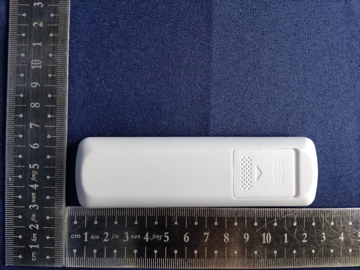
2AD9E-154217
Aug 05, 2023RM15 BLE MESH HAND-HELD REMOTE Control
Equipment Class
DTS - Digital Transmission System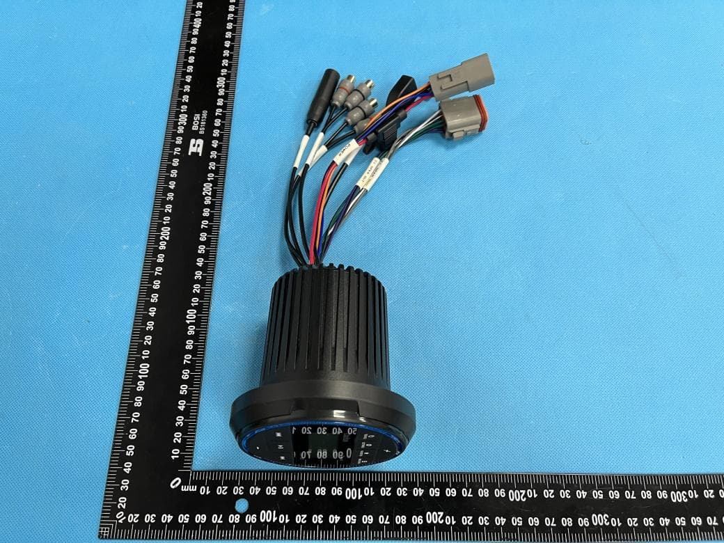
2AD9E-CMM10GR
Apr 23, 2023Marine Source Unit
Equipment Class
DSS - Part 15 Spread Spectrum Transmitter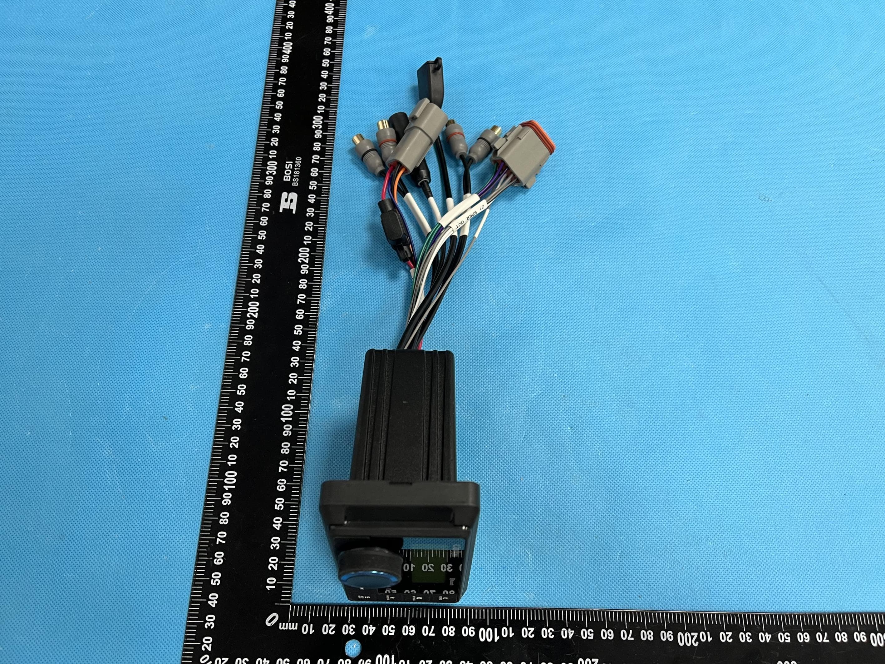
2AD9E-CMM10I
Apr 23, 2023Marine Source Unit
Equipment Class
DSS - Part 15 Spread Spectrum Transmitter
2AD9E-CMM10
Apr 23, 2023Marine Source Unit
Equipment Class
DSS - Part 15 Spread Spectrum Transmitter