2AD9EMBT-CRXBluetooth Audio Receiver
JL Audio, Inc.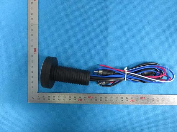
Click to zoom
Application Details
- Equipment Class
- DXX - Part 15 Low Power Communication Device Transmitter
- Date of Grant
- Nov 09, 2015
- Application Purpose
- Original Equipment
- Date of Application
- Nov 09, 2015
- Equipment Note
- Bluetooth Audio Receiver
- Frequency Range
- 2402.00000000 - 2480.00000000
- Company
- JL Audio, Inc.
- Country
- United States
Documents & Files
Document Text
Text extracted from the exhibit documents filed with the FCC. Open a document above to read the original.
Users Manual
Weatherproof Bluetooth® Controller / Receiver Product Description The MBT-CRX is a water-resistant (IPX6 rated) Bluetooth® receiver designed for marine and powersports applications. It can be used as a stand-alone Bluetooth® source unit/receiver, connecting directly to an amplifier. It can also be used as an add-on Bluetooth® controller/ receiver, connected to an existing head unit’s line-level/auxiliary inputs. The MBT-CRX is not designed to drive loudspeakers directly. What’s Included (1) MBT-CRX Bluetooth controller/receiver (1) Threaded fastening collar (1) Thin round gasket (1) Thick round gasket (1) Square adaptor plate (1) Square adaptor gasket (4) Stainless steel mounting screws (1) User Manual Installation Applications This product is designed for operation in 12 volt, negative-ground electrical systems. Using this product in systems with positive ground and/or voltages other than 12 volts may result in damage to the product and will void the warranty. This product is not certified or approved for use in aircraft. Safety Considerations • Whenever possible, mount this product in a dry, well-ventilated location that does not interfere with other factory installed electronic devices. If a dry environment is not available, a location that is not exposed to heavy splashing may be used. • While this product is designed to be water- resistant, it should never be submerged under water or subjected to high-pressure water spray. • Do not mount in an engine compartment or in any areas of extreme heat. • Ensure this product is securely installed so that it does not come loose in the event of a collision/sudden jolt or as a result of repeated vibrations during normal operation. • Check before drilling to make sure that you will not be drilling into an exterior panel/ hull, fuel tank, gas/brake line, wiring harness, or other vital system. • Do not run system wiring outside or underneath the vehicle/vessel. This is an extremely dangerous practice, which can result in severe damage/injury. • Protect all system wires from sharp edges (metal, fiberglass, etc.) by carefully routing them, tying them down and using grommets and loom where appropriate. • Secure all wiring as needed, using cable ties or wire clamps to protect them from moving parts and sharp edges. • Do not replace the power wire fuse with one of a different value. Never bypass the fuse. Mounting & Installation The design of the MBT-CRX requires just a single hole for installation. Its easy-to- use threaded-collar mounting system can accommodate installations in flat surfaces up to 1.75 inches (4.5 cm) thick. A front-mounted adaptor plate is included for installations in panels exceeding 1.75 inches (4.5 cm) thick, or where rear access is limited or not possible. Refer to the diagrams below for your specific mounting application. Standard Collar-Mount Installation Front-Mount Adaptor Installation IPX6 WATER RESISTANT FCC ID:2AD9EMBT-CRX Wiring Diagram Pairing Your Device (required for operation) 1. Ensure your streaming device has Bluetooth® enabled and that the MBT-CRX is on (backlit in blue). The JL Audio logo on the MBT-CRX will blink to indicate it is in pairing mode. 2. Within your streaming device’s Bluetooth® setup menu, select “MBT-CRX” from the list of pairable devices. 3. When successfully connected, the JL Audio logo on the MBT-CRX will stop blinking and remain lit. A single beep will be heard through the connected audio system. Note: If optional connection is made to a head unit’s remote turn-on output, the head unit will turn the MBT-CRX on/off and the MBT-CRX power button will no longer operate. Pairing Considerations cont’d When a connected streaming device is out of range for more than one minute, the MBT-CRX will automatically disconnect this streaming device and return to pairing mode (JL Audio logo will blink). When that same device comes back into range, it should be reconnected to the MBT-CRX manually. Controlling Audio Playback Once connected, use the controls on the MBT-CRX to adjust volume up/down, track selection and play/pause. 2-Year Limited Warranty (U.S.A.) Visit www.jlaudio.com for warranty details. For Service Information in the U.S.A. please call JL Audio customer service: (954) 443-1100 during normal business hours (Eastern Time) • JL Audio, Inc • 10369 N Commerce Parkway, Miramar, FL 33025 International Warranties: Products purchased outside the United States of America are covered only by that country’s distributor and not by JL Audio, Inc. 10-08-2015 • Printed in China Pairing Considerations Multiple devices can be paired to the MBT-CRX, but only one streaming device can connect at one time. The MBT-CRX will remember the last device that was connected to it and reconnect with it automatically. If that streaming device is not active, then other paired streaming devices can connect manually, or new streaming devices can be paired. Specifications Bluetooth® ProfileA2DP (High-Quality, Stereo Audio) Bluetooth® Core Specification Version 4.0 with aptX® Frequency Response20 Hz – 18 kHz (±1dB) OutputsOne Stereo Pair, Low-Level RCA Plugs Output Voltage2V RMS Signal to Noise Ratio93 dB (20 Hz – 20 kHz) Input Operating Voltage8 – 28 VDC Current Draw 48 mA (at idle) 64 mA (at full output) Remote Turn-on Output Capacity 350 mA (max) Fuse Rating2A Mini ATC Connection Range*Up to 35 ft / 11 m *Maximum range is achieved in line-of-sight installations, actual range will vary based on installation specifics. Control Legend N OTE : This equipment has been tested and found to comply with the limits for a Class B digital device, pursuant to part 15 of the FCC Rules. These limits are designed to provide reasonable protection against harmful interference in a residential installation. This equipment generates, uses and can radiate radio frequency energy and, if not installed and used in accordance with the instructions, may cause harmful interference to radio communications. However, there is no guarantee that interferenc…
Text truncated - open the document above for the full version.
Cover Letter(s)
JL Audio, Inc. Address:10369 North Commerce Pkwy Miramar, Florida 33025-3962 United States TEL: (602) 431-1700-3120 FAX: (954) 443-1111 Federal Communications Commission Authorization and Evaluation Division Equipment Authorization Branch 7435 Oakland Mills Road Columbia, MD 21046 11/4/2015 To whom it may concern: We, the undersigned, hereby authorize Eurofins Product Service GmbH to act on our behalf in all matters relating to applications for equipment authorization FCC ID: 2AD9EMBT-CRX including the signing of all documents related to these matters. Any and all acts carried out by Eurofins Product Service GmbH on our behalf shall have the same effect as acts of our own. We also hereby certify that no party to this application is subject to a denial of benefits, including FCC benefits, pursuant to Section 5301 of the Anti-Drug Abuse Act of 1988, 21 U.S.C. 862. Sincerely, Signature JL Audio, Inc. Contact person: Stephen Leigh Title: Director Electronics
Cover Letter(s)
JL Audio, Inc. Address:10369 North Commerce Pkwy Miramar, Florida 33025-3962 United States TEL: (602) 431-1700-3120 FAX: (954) 443-1111 Federal Communications Commission Equipment Authorization Branch 7435 Oakland Mills Road Columbia, MD 21046 11/4/2015 Request for Confidentiality Company name: JL Audio, Inc. FCC ID: 2AD9EMBT-CRX FCC Part 15 Certification Gentlemen, In accordance with CFR 47 § 0.459, JL Audio, Inc. hereby requests confidentiality of following attachments: (1) schematic diagrams, (2) detailed block diagrams, (3) detailed operational descriptions, (4) parts lists. These documents contain detailed system and equipment description and related information about the product which JL Audio, Inc. considers to be proprietary, confidential and a custom design and otherwise would not release to the general public. Since the design is a basis from which future technological products will evolve, JL Audio, Inc. considers that this information would be of benefit to its competitors and that the disclosure of the information in these documents would give competitors an unfair advantage in the market. Sincerely, Signature [Stephen Leigh] [Director Electronics] JL Audio, Inc. 10369 North Commerce Pkwy Miramar,Florida 33025-3962 United States
External Photos
External Photos TOP VIEW OF EUT BOTTOM VIEW OF EUT FRONT VIEW OF EUT BACK VIEW OF EUT LEFT VIEW OF EUT RIGHT VIEW OF EUT
ID Label/Location Info
FCC ID Label Location FCC ID: 2AD9EMBT-CRX
Internal Photos
Internal Photos OPEN VIEW OF EUT-1 OPEN VIEW OF EUT-2 INTERNAL VIEW OF EUT-1 INTERNAL VIEW OF EUT-2 INTERNAL VIEW OF EUT-3 INTERNAL VIEW OF EUT-4 INTERNAL VIEW OF EUT-5 INTERNAL VIEW OF EUT-6 INTERNAL VIEW OF EUT-7 INTERNAL VIEW OF EUT-8 Antenna INTERNAL VIEW OF EUT-9 INTERNAL VIEW OF EUT-10 INTERNAL VIEW OF EUT-11
RF Exposure Info
RF Exposure evaluation Product Description: Bluetooth Audio Receiver Model Number: MBT-CRX FCC ID: 2AD9EMBT-CRX According to 447498 D01 General RF Exposure Guidance v05 The 1-g and 10-g SAR test exclusion thresholds for 100 MHz to 6 GHz at test separation distances ≤ 50 mm are determined by: [(max. power of channel, including tune-up tolerance, mW)/(min. test separation distance, mm)] ·[√f(GHz)] ≤ 3.0 for 1-g SAR and ≤ 7.5 for 10-g extremity SAR, where f(GHz) is the RF channel transmit frequency in GHz Power and distance are rounded to the nearest mW and mm before calculation According to the follow transmitter output power(P t )formula: P t =(E x d) 2 /(30 x g t ) P t =transmitter output power in watts g t =numeric gain of the transmitting antenna (unitess) E=electric field strength in V/m d=measurement distance in meters (m) According to the above test data, Emax=99.28dBuv/m=0.092V/m,d=3m,g t =1 P t =(E x d) 2 /(30 x g t )=(0.092x3) 2 /(30x1)=0.002539W=2.54mW The result is rounded to one decimal place for comparison Worse case is as below: [2480MHz -2.54mW output power] (2.54mW /5mm) .[√2.480(GHz)]= 0.8<3.0 for 1-g SAR Then SAR evaluation is not required NOTE: For the maximum power, you can refer FCC test report.
Test Report
FCC ID APPLI PROD U BRAND MODE CLIEN DATE O STAND TEST P REPOR A CAUTI This re test lab D CATION P U UCT DESIG D NAME EL NAME T OF ISSUE DARD(S) PROCEDUR RT VERSIO Attestat ION: eport shall boratory an FC Rep URPOSE GNATION RE(S) ON tion of G not be repr nd shall no C Te port No.: : 2AD9 : Origi : Bluet : N/A : MBT : JL Au : Oct.2 : FCC P : V1.0 Global C roduced ex t be quoted est R AGC0167 9EMBT‐CR inal Equipm tooth Audi T‐CRX udio, Inc. 24,2015 Part 15 Rul Complia xcept in full d out of con Rep 79150701 RX ment o Receiver les ance (Sh l without th ntext. port 1FE03 henzhen he written t n) Co., L permission Page 1 o Ltd n of the of 77 Report No.: AGC01679150701FE03 Page 2 of 77 Report Revise Record Report Version Revise Time Issued Date Valid VersionNotes V1.0 / Oct.24,2015 Valid Original Report Report No.: AGC01679150701FE03 Page 3 of 77 TABLE OF CONTENTS 1. VERIFICATION OF CONFORMITY ...................................................................................... 4 2. GENERAL INFORMATION .................................................................................................. 5 2.1. PRODUCT DESCRIPTION ........................................................................................................... 5 2.2. TABLE OF CARRIER FREQUENCYS .......................................................................................... 5 3. MEASUREMENT UNCERTAINTY........................................................................................ 7 4. DESCRIPTION OF TEST MODES ........................................................................................ 7 5. SYSTEM TEST CONFIGURATION ...................................................................................... 8 5.1. CONFIGURATION OF EUT SYSTEM .......................................................................................... 8 5.2. EQUIPMENT USED IN EUT SYSTEM ......................................................................................... 8 5.3. SUMMARY OF TEST RESULTS .................................................................................................. 8 6. TEST FACILITY .................................................................................................................... 9 7 ALL TEST EQUIPMENT LIST ............................................................................................... 9 8. RADIATED EMISSION ....................................................................................................... 10 8.1TEST LIMIT ................................................................................................................................... 10 8.2. MEASUREMENT PROCEDURE ................................................................................................ 11 8.3. TEST SETUP .............................................................................................................................. 12 8.4. TEST RESULT ............................................................................................................................ 15 9. BAND EDGE EMISSION .................................................................................................... 41 9.1. MEASUREMENT PROCEDURE ................................................................................................ 41 9.2 TEST SETUP ............................................................................................................................... 41 9.3 RADIATED TEST RESULT .......................................................................................................... 42 10. 20DB BANDWIDTH .......................................................................................................... 50 10.1. MEASUREMENT PROCEDURE .............................................................................................. 50 10.2. TEST SET-UP ........................................................................................................................... 50 10.3. LIMITS AND MEASUREMENT RESULTS ................................................................................ 50 11. FCC LINE CONDUCTED EMISSION TEST ..................................................................... 60 11.1. LIMITS OF LINE CONDUCTED EMISSION TEST ................................................................... 60 11.2. BLOCK DIAGRAM OF LINE CONDUCTED EMISSION TEST ................................................. 60 11.3. PRELIMINARY PROCEDURE OF LINE CONDUCTED EMISSION TEST .............................. 61 11.4. FINAL PROCEDURE OF LINE CONDUCTED EMISSION TEST ............................................. 61 11.5. TEST RESULT OF LINE CONDUCTED EMISSION TEST ....................................................... 62 APPENDIX A: PHOTOGRAPHS OF TEST SETUP ............................................................... 66 APPENDIX B: PHOTOGRAPHS OF EUT .............................................................................. 68 1 A A M A P B T D D C R W T e t h th . VERIFIC Applicant Address Manufacture Address Product Des Brand Name Test Model Date of test Deviation Condition of Report Temp We hereby ce The above eq valuation, te he procedur his report is CATION OF er signation e f Test Samp plate ertify that: quipment wa est procedur es given in A in complian F CONFOR JL Au 10369 AVS ( NO. 7 NB C Blueto N/A MBT- Oct.19 None ple Norm AGCR as tested by res, and equ ANSI C63.4 ce with radi a Tested By Reviewed B Approved B RMITY udio, Inc. 9 North Com (Ningbo) Ind 7, 59TH, CH ITY, ZHE JIA ooth Audio R CRX 9,2015 and al RT-US-BR/R y Complianc uipment con (2009) and ated emissio y Je r By Forr e By Solge A mmerce Pkw dustrial Co., HUANG FU R ANG ,CHINA Receiver Oct.23,2015 RF ce Certificatio figurations s the energy on limits of F rry Xiao(Xiao est Lei(Lei Y r Zhang(Zha Authorized O wy Miramar, Ltd. ROAD, XIAO A 5 on Service ( shown in thi emitted by t FCC Rules P o Wang) Yonggang) ang Hongyi) Officer Report FL 33025-3 O GANG IND (Shen…
Text truncated - open the document above for the full version.
Test Setup Photos
APPENDIX IV PHOTOGRAPHS OF TEST SETUP FCC LINE CONDUCTED EMISSION TEST SETUP FCC RADIATED EMISSION TEST SETUP
Contact Information
Applicant
Mitchell Phillipi(Sr. Manager, WW Compliance)
Test Firm
Compliance Certification Services (Shenzhen) Inc.Harry Li
Technical Specifications
| # | Rule Parts | Frequency Range | Power Output |
|---|---|---|---|
| 1 | 15C | 2.40 GHz - 2.48 GHz | - |
Other Applications from JL Audio, Inc.
2AD9E-MM55HR
Jun 27, 2024MediaMaster Source Unit Hidden Receiver
Equipment Class
DSS - Part 15 Spread Spectrum Transmitter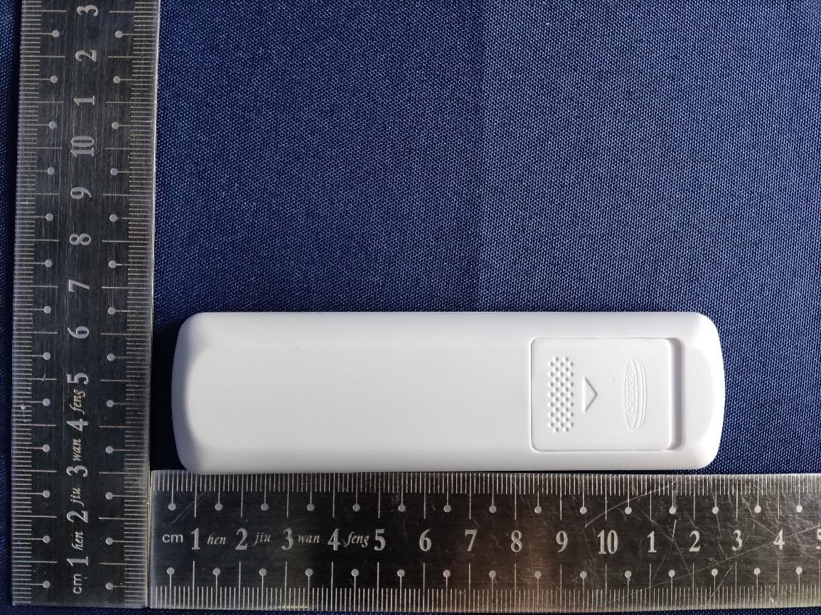
2AD9E-154217
Aug 05, 2023RM15 BLE MESH HAND-HELD REMOTE Control
Equipment Class
DTS - Digital Transmission System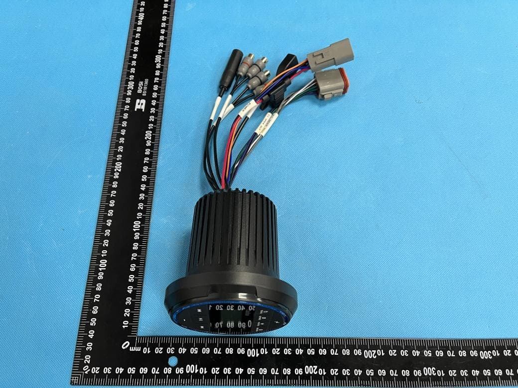
2AD9E-CMM10GR
Apr 23, 2023Marine Source Unit
Equipment Class
DSS - Part 15 Spread Spectrum Transmitter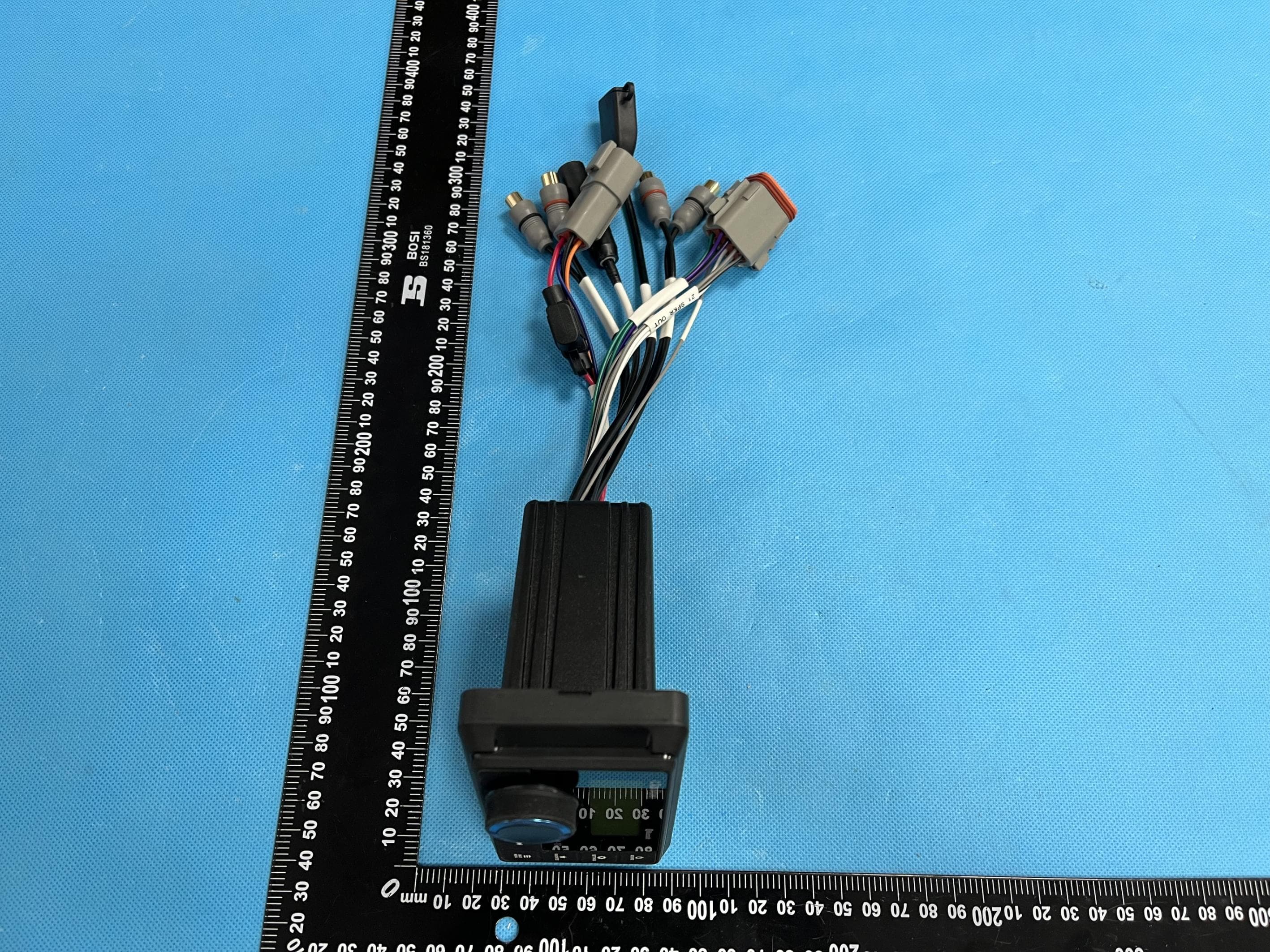
2AD9E-CMM10I
Apr 23, 2023Marine Source Unit
Equipment Class
DSS - Part 15 Spread Spectrum Transmitter
2AD9E-CMM10
Apr 23, 2023Marine Source Unit
Equipment Class
DSS - Part 15 Spread Spectrum Transmitter