2AD9T-TRC2425DABCAR AUDIO SYSTEM
Axion AG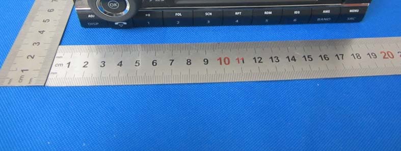
Click to zoom
Application Details
- Equipment Class
- DSS - Part 15 Spread Spectrum Transmitter
- Date of Grant
- May 02, 2015
- Application Purpose
- Original Equipment
- Date of Application
- May 02, 2015
- Equipment Note
- CAR AUDIO SYSTEM
- Frequency Range
- 2402.00000000 - 2480.00000000
- Company
- Axion AG
- Country
- Germany
Documents & Files
Document Text
Text extracted from the exhibit documents filed with the FCC. Open a document above to read the original.
Users Manual
TRC2425DAB+ P/N:127075006476 USB / CD / DAB / Bluetooth / I-Mode Truck Radio 2 CONTENTS CONTENTS ......................................................................................................................................... 2 SAFETY INFORMATION ..................................................................................................................... 2 PANEL CONTROLS ............................................................................................................................ 6 GENERAL OPERATION ...................................................................................................................... 7 CD/MP3/WMA OPERATIONS ............................................................................................................. 9 USB/MP3 PLAYBACK ....................................................................................................................... 11 BLUETOOTH OPERATION ............................................................................................................... 12 TUNER OPERATION ........................................................................................................................ 13 DAB OPERATION ............................................................................................................................. 15 I-MODE OPERATION ........................................................................................................................ 16 MENU FUNCTION ............................................................................................................................. 16 SOUND SETTINGS ........................................................................................................................... 18 ELECTRICAL CONNECTIONS .......................................................................................................... 18 INSTALLING GUIDE.......................................................................................................................... 19 TROUBLESHOOTING ....................................................................................................................... 20 SPECIFICATION ............................................................................................................................... 21 SAFETY INFORMATION Thank you for purchasing this product. Please read thr ough these operating instructions so you will know how to operate your model properly. After you have finished reading the instructions, keep the manual in a safe place for future reference. WARNINGS Do not operate any function that takes your attention away from safely driving your vehicle. Any function that requires your prolonged attention should only be performed after coming to a complete stop. Keep the volume at a level where you can still hear e nvironment noises while driving. Excessive volume levels tha t obscure sounds such as emergency vehicle sirens etc. can be dangerous and may result in an accident. Listening at loud volume levels in a car may also cause hearing damage. Do not disassemble. Doing so may result in an accident, fire or electric shock. Use only in cars with a 24 Volt negative ground. Check with your dealer if you are not sure. Use the correct Ampere rating when replacing fuses. Failure to do so may resu lt in fire or electric sh ock. Do not block the ventilation openings or radiator panels of the device. Doing so may cause heat to build up inside and may result in fire. ............................................................................................................................. 22 FCC STATEMENT 3 Do not place foreign obejcts in insertion slots or gaps. Doing so may result in personal injury or damage to the product. PRECAUTIONS Product Cleaning Use a soft dry cloth for periodic cleaning of the product. For more severe stains, please dampen the cloth with water only. Anything else has the chance of dissolving the paint or damaging the plastic. Temperature Be sure the temperature inside the vehicle is between +60°C (+140°F) and –10°C (+14°F) before turning your unit on. Moisture Condensation You may notice the CD playback sound wavering due to condensation. If this happens, remove the disc from the player and wait about an hour for the moisture to evaporate. Damaged Disc Do not attempt to play cracked, warped, or damaged discs. Playing a bad disc could severely damage the playback mechanism. Maintenance If you have problems, do not attempt to repair the unit yourself. Return it to your dealer for servicing. Never Attempt the Following Do not grip or pull out the disc while it is being pulled back into the player by the automatic reloading mechanism. Do not attempt to insert a disc into the unit when the unit power is off. Inserting Discs Your player accepts only one disc at a time for playback. Do not attempt to load more than one disc. Make sure the label side is facing up when you insert the disc. “Error 3” will be displayed on your player if you insert a disc incorrectly. Playing a disc while driving on a very bumpy road may result in skips, but this will not scratch the disc or damage the player. Irregular Shaped Discs Be sure to use round shape discs only for this unit and never use any special shape discs. Use of special shape discs may cause damage to the mechanism. Installation Location Make sure this unit will not be installed in a location subjected to: Direct sun and heat High humidity and water Excessive dust Excessive vibrations Disc Accessories There are various accessories available on the market for protecting the disc surface and improving sound quality. However, most of them will influence the thickness and/or diameter of the disc. Using such accessories can cause the disc to be out of standard specifications and may create operational problems. We recommend not using these accessories on discs. 4 On handling Compact Discs (CD/CD-R/CD-RW) Do not touch the sur…
Text truncated - open the document above for the full version.
Cover Letter(s)
Model difference letter We declare that about models CR1225DAB+, CR1223BT, MCR1118DAB+, MCR1116BT, All models are electrically identical, only the appearance, color, trade name and model No. are different. We declare that about models TRC2425DAB+, TRC2423BT, MCR2418DAB+, MCR2416BT ,All models are electrically identical, only the appearance, color, trade name and model No. are different.
External Photos
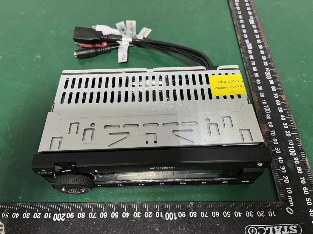
Dongguan Dongdian Testing Service Co., Ltd Report No: DDT-R15Q0125-2E1 Page 60 of 66 14. Photos of the EUT Dongguan Dongdian Testing Service Co., Ltd Report No: DDT-R15Q0125-2E1 Page 61 of 66 Dongguan Dongdian Testing Service Co., Ltd Report No: DDT-R15Q0125-2E1 Page 62 of 66
Internal Photos
Dongguan Dongdian Testing Service Co., Ltd Report No: DDT-R15Q0125-2E1 Page 63 of 67 Dongguan Dongdian Testing Service Co., Ltd Report No: DDT-R15Q0125-2E1 Page 64 of 67 Dongguan Dongdian Testing Service Co., Ltd Report No: DDT-R15Q0125-2E1 Page 65 of 67 Dongguan Dongdian Testing Service Co., Ltd Report No: DDT-R15Q0125-2E1 Page 66 of 67 Dongguan Dongdian Testing Service Co., Ltd Report No: DDT-R15Q0125-2E1 Page 67 of 67 END OF REPORT
RF Exposure Info
RF Exposure evaluation According to 447498 D01 General RF Exposure Guidance v05 The 1-g and 10-g SAR test exclusion thresholds for 100 MHz to 6 GHz at test separation distances ≤ 50 mm are determined by: [(max. power of channel, including tune-up tolerance, mW)/(min. test separation distance, mm)] ·[√f(GHz)] ≤ 3.0 for 1-g SAR and ≤ 7.5 for 10-g extremity SAR, where: f(GHz) is the RF channel transmit frequency in GHz Power and distance are rounded to the nearest mW and mm before calculation The result is rounded to one decimal place for comparison Worse case is as below: [2402MHz, 0.85dBm (1.22mW) output power] (1.22/5) ·[√2.402(GHz)]= 0.378 <3.0 for 1-g SAR Then SAR evaluation is not required Leo Liu 2015/3/19
Test Report
Dongguan Dongdian Testing Service Co., Ltd Report No:DDT-R15Q0125-2E1 Page 1 of 67 FCC CERTIFICATION TEST REPORT FOR Issued By: Dongguan Dongdian Testing Service Co., Ltd. Add: No. 17, Zongbu Road 2, Songshan Lake Sci&Tech, Industry Park, Dongguan City, Guangdong Province, China, 523808 Tel: +86-0769-22891499 Http://www.dgddt.com Applicant : AXION AG Address : Röntgenstrasse 4 D-89264 Weißenhorn Equipment under Test : CAR AUDIO SYSTEM Model No : TRC2425DAB+, TRC2423BT, MCR2418DAB+, MCR2416BT Trade Mark : KIENZLE AUTOMOTIVE FCC ID : 2AD9T-TRC2425DAB Manufacturer : Huizhou Foryou General Electronics Co., Ltd. Address : North Shangxia Road, Dongjiang Hi-tech Industry Park, Huizhou, Guangdong Province, 516005, P R China Report No: DDT-R15Q0125-2E1 Issued Date: Mar. 6, 2015 Dongguan Dongdian Testing Service Co., Ltd Report No:DDT-R15Q0125-2E1 Page 2 of 67 TABLE OF CONTENTS Test report declares......................................................................................................................4 1. Summary of test results ............................................................................................................... 5 2. General test information .............................................................................................................. 6 2.1. Description of EUT ..................................................................................................................... 6 2.2. Assistant equipment used for test ................................................................................................ 6 2.3. Block diagram of EUT configuration for test ............................................................................. 6 2.4. Test environment conditions ....................................................................................................... 7 2.5. Test laboratory............................................................................................................................. 7 2.6. Measurement uncertainty ............................................................................................................ 7 3. Maximum Peak Output Power ....................................................................................................8 3.1. Test equipment ............................................................................................................................ 8 3.2. Block diagram of test setup ......................................................................................................... 8 3.3. Limits .......................................................................................................................................... 8 3.4. Test Procedure............................................................................................................................. 9 3.5. Test Result................................................................................................................................... 9 4. 20dB Bandwidth........................................................................................................................ 10 4.1. Test equipment .......................................................................................................................... 10 4.2. Block diagram of test setup ....................................................................................................... 10 4.3. Limits ........................................................................................................................................ 10 4.4. Test Procedure........................................................................................................................... 10 4.5. Test Result................................................................................................................................. 11 4.6. Original test data ....................................................................................................................... 11 5. Carrier Frequency Separation.................................................................................................... 15 5.1. Test equipment .......................................................................................................................... 15 5.2. Block diagram of test setup ....................................................................................................... 15 5.3. Limits ........................................................................................................................................ 15 5.4. Test Procedure........................................................................................................................... 15 5.5. Test Result................................................................................................................................. 15 5.6. Original test data ....................................................................................................................... 16 6. Number Of Hopping Channel ...................................................................................................17 6.1. Test equipment .......................................................................................................................... 17 6.2. Block diagram of test setup ....................................................................................................... 17 6.3. Limits ........................................................................................................................................ 17 6.4. Test Procedure........................................................................................................................... 17 6.5. Test Result................................................................................................................................. 17 6.6. Original test data ..................................................................…
Text truncated - open the document above for the full version.
Test Setup Photos
Dongguan Dongdian Testing Service Co., Ltd Report No: DDT-R15Q0125-2E1 Page 59 of 66 13. Test setup photograph
Contact Information
Applicant
Rolf Mayer(CEO)
Test Firm
Dongguan Dongdian Testing Service Co.,LtdJamy Yu
[email protected]086-0769-22891499
Technical Specifications
| # | Rule Parts | Frequency Range | Power Output |
|---|---|---|---|
| 1 | 15C | 2.40 GHz - 2.48 GHz | 1.22 mW |
Other Applications from Axion AG
2AD9T-CR1226DAB
Jul 17, 2023CAR AUDIO SYSTEM
Equipment Class
DSS - Part 15 Spread Spectrum Transmitter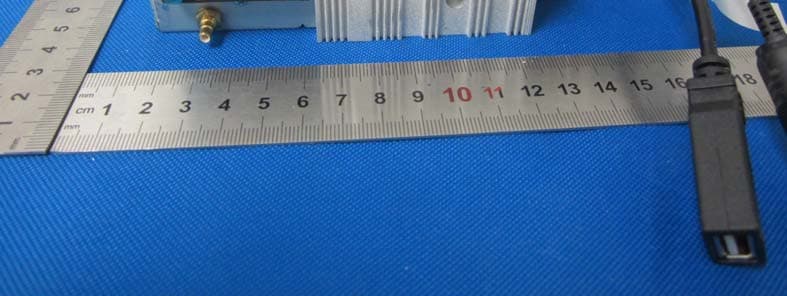
2AD9T-CR1225DAB
May 02, 2015CAR AUDIO SYSTEM
Equipment Class
DSS - Part 15 Spread Spectrum Transmitter