2ADBY0501007Battery operated wireless pulse counter unit
Dyzle Services B.V.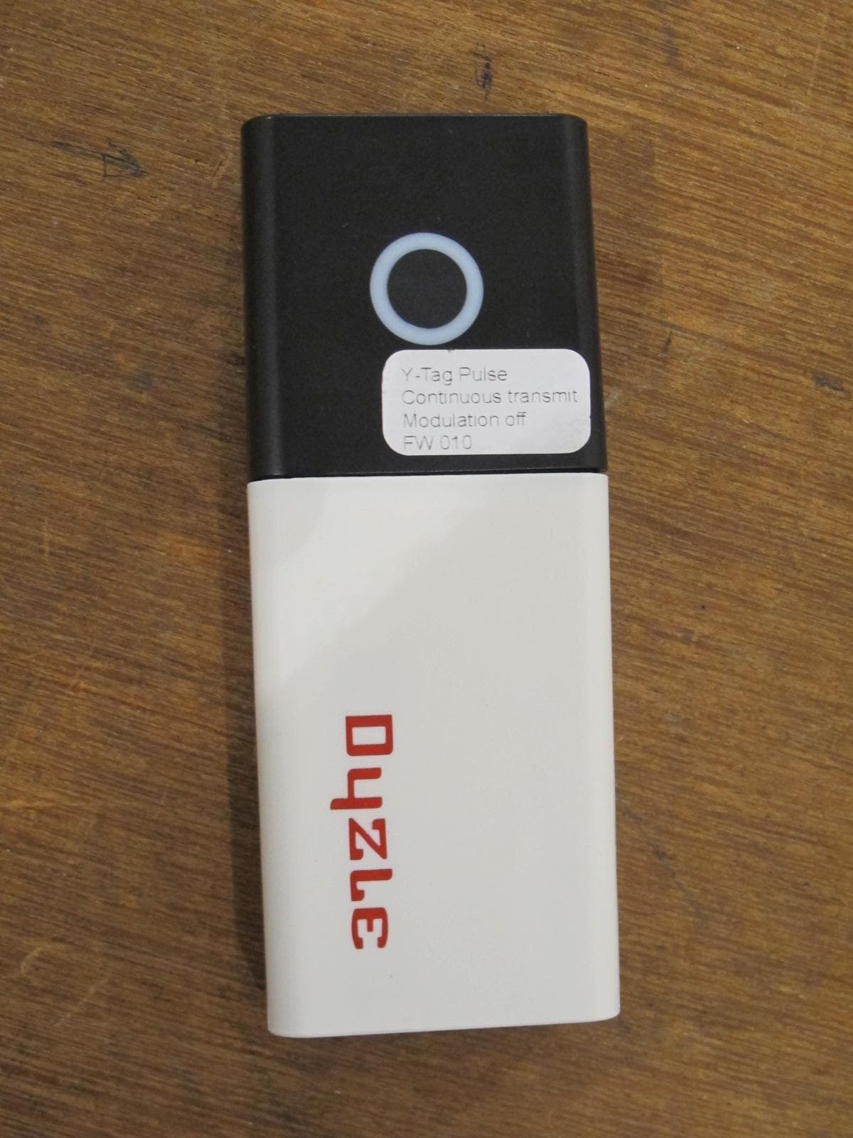
Click to zoom
Application Details
- Equipment Class
- DXX - Part 15 Low Power Communication Device Transmitter
- Date of Grant
- Aug 23, 2015
- Application Purpose
- Original Equipment
- Date of Application
- Aug 12, 2015
- Equipment Note
- Battery operated wireless pulse counter unit
- Frequency Range
- 2404.00000000 - 2480.00000000
- Company
- Dyzle Services B.V.
- Country
- Netherlands
Documents & Files
Document Text
Text extracted from the exhibit documents filed with the FCC. Open a document above to read the original.
Users Manual
Dyzle BV, 2d Transistorstraat, 1322 CE Almere (NL), Tel.: +31(0)36-5233900, Fax: +31(0)36-5233999 © 2015 Dyzle User Manual for Y-Tag Pulse, version 1.3, March 2015 1 User Manual for: Y-Tag Pulse Product code 050 1007 001 Version 1.3, March 2015 © 2015 Dyzle Dyzle BV, 2d Transistorstraat, 1322 CE Almere (NL), Tel.: +31(0)36-5233900, Fax: +31(0)36-5233999 © 2015 Dyzle User Manual for Y-Tag Pulse, version 1.3, March 2015 2 Foreword This User Manual is intended for users and installers of the Y-Tag Pulse. Read the User Manual thoroughly before proceeding to install or use the Y-Tag Pulse. This product is delivered exclusively to businesses and may only be installed and operated by installers who have been trained by Dyzle. This User Manual makes reference to the Dyzle Hardware Installation Manual. This document provides information on installation and maintenance of the Y-Tag. The Dyzle Portal 2 User Manual describes how to use the online Portal. You can manage your settings and view the data that is submitted by the sensors and Y-Gates in the Portal. Contact your supplier's support department to obtain a copy of the latest version of the Manuals. Table of Contents Foreword .............................................................................................................................. 2 General description of the Dyzle solution ............................................................................. 2 General description of the Y-Tag Pulse ............................................................................... 3 Product specifications .......................................................................................................... 3 Safety ................................................................................................................................... 3 Placement and installation ................................................................................................... 3 Making the device operational and resetting it ..................................................................... 4 Maintenance and battery replacement ................................................................................. 4 Warranty ............................................................................................................................... 4 Declaration of conformity ...................................................................................................... 4 Disposal ................................................................................................................................ 4 General description of the Dyzle solution The Y-Tag Pulse is part of the Dyzle solution. The solution consists of a personal dashboard (online Portal) and the necessary hardware. The hardware will take and send measurements to Dyzle in the form of data packages, which can contain information such as: temperature measurements; door monitoring (door open / closed); humidity (% RH); electricity consumption; location (GPS; only for a mobile location); CO 2 . The hardware consists of sensors (Y-Tags) and a base station (Y-Gate) that communicate wirelessly with one another. The components contain electronics that are powered by an adapter, the vehicle's battery, or a battery-pack. The components are NOT waterproof, unless specified otherwise, and must therefore be protected from water and other liquids. Other than the wiring and sensors, which are designed for high-temperature applications and are explicitly specified as such, the hardware itself should NOT be exposed to temperatures above 50°C. Dyzle sensors can be used for measuring temperatures in cold rooms, freezers, refrigerators, refrigerated displays, and promotional displays. Both air- and product-temperature are measurable and are therefore distinguished from one another. Outfitting a delivery truck or van, which contain food or pharmaceutical products, with the hardware allows for continuous recording of position and / or temperature of the conditioned space. The Dyzle solution is designed to address the needs of customers in the food, pharmaceutical / care and transport industries in terms of: Automated temperature registration (24/7); Notification service in the event of a temperature exceedance by email, premium SMS or IVR*; Automated HACCP / QA reports. * For Interactive Voice Response (IVR): ask the support department about the possibilities. Dyzle BV, 2d Transistorstraat, 1322 CE Almere (NL), Tel.: +31(0)36-5233900, Fax: +31(0)36-5233999 © 2015 Dyzle User Manual for Y-Tag Pulse, version 1.3, March 2015 3 General description of the Y-Tag Pulse The Dyzle Y-Tag Pulse is a wireless, splash-proof (IP44) pulse sensor. The Y-pulse is used to integrate water-, gas- and electricity meters in the Dyzle solution. The Y-Pulse can therefore be connected to the pulse output of the relevant water-, gas- and electricity meters. The Y-Tag Pulse takes a measurement every five minutes and sends the measurement data to the Y-Gate. The Y-Gate – the base station - collects measurement data from the Y-Tag(s) and sends the data to the server. Product specifications* Product code 050 1007 001 Pulse type Voltage pulse: pulse duration > 2 msec, pulse voltage 1 to 10V Optocoupler: pulse duration > 2 msec, capacity < 1nF Connectivity range 100 m (unobstructed) Measurement interval 5 minutes Memory A maximum of 65,000 pulses (if the connection to the Y-Gate is lost) Power supply 3.6 V DC (Battery pack) Battery life 1 year (room temperature) Ambient conditions -25 °C to +50 °C Water resistance IP44 (splash-proof) * Refer to the separate product specifications overview for the comprehensive product features. Safety Installation of the Y-Tag Pulse requires general knowledge of safe work practices, therefore may only be carried out by personnel holding the required operational Safety Certificate, and should also have the necessary knowledge of the spaces, equipment and vehicles that will be measured…
Text truncated - open the document above for the full version.
External Photos
Photographs module 20114146301 External PHOTOGRAPH 1: - OVERVIEW OF Y-TAG PULS 1.0 / 050 1007 001 SET ............................................................... 2 PHOTOGRAPH 2: - TRANSCEIVER MODULE OF Y-TAG PULS 1.0 / 050 1007 001 SET, FRONT VIEW ........................ 3 PHOTOGRAPH 3: - TRANSCEIVER MODULE OF Y-TAG PULS 1.0 / 050 1007 001 SET, REAR VIEW .......................... 4 PHOTOGRAPH 4: - BATTERY PACK OF Y-TAG PULS 1.0 / 050 1007 001 SET, TOP VIEW ........................................ 5 PHOTOGRAPH 5: - BATTERY PACK OF Y-TAG PULS 1.0 / 050 1007 001 SET, BOTTOM VIEW .................................. 6 Page: 2 of 6 Photograph module 20114146301 external Photograph 1: - Overview of Y-Tag puls 1.0 / 050 1007 001 set Page: 3 of 6 Photograph module 20114146301 external Photograph 2: - Transceiver module of Y-Tag puls 1.0 / 050 1007 001 set, front view Page: 4 of 6 Photograph module 20114146301 external Photograph 3: - Transceiver module of Y-Tag puls 1.0 / 050 1007 001 set, rear view Page: 5 of 6 Photograph module 20114146301 external Photograph 4: - Battery pack of Y-Tag puls 1.0 / 050 1007 001 set, top view Page: 6 of 6 Photograph module 20114146301 external Photograph 5: - Battery pack of Y-Tag puls 1.0 / 050 1007 001 set, bottom view
ID Label/Location Info
0560 Model 050 1007 001 Designed by Dyzle FCC ID:2ADBY0501007
ID Label/Location Info
0560 Model 050 1007 002 Designed by Dyzle FCC ID:2ADBY0501007
Test Report
Radio test report 20114146301-Ver 1.00 based on: - FCC part 15; subpart C; section 15.249 & 15.209 (10-1-13 edition) - FCC part 15, subpart B: section 15.109 (10-1-13 edition) Battery operated wireless pulse counter unit Dyzle Y-Tag puls 1.0 / 050 1007 001 set Revision history Report number: 20114146301-Ver 1.00 Revision history REVISION DATE REMARKS REVISED BY Ver 1.00 2015 02 12 Initial release ing. J.C. le Clercq Ver 0.50 2014 11 07 Version for peer review ing. J.C. le Clercq Main module Report number: 20114146301-Ver 1.00 Contents REVISION HISTORY ..................................................................................................................................... 2 MAIN MODULE .............................................................................................................................................. 4 1 ..... INTRODUCTION ...................................................................................................................................... 4 2 ..... PRODUCT ............................................................................................................................................... 5 3 ..... TEST SCHEDULE ..................................................................................................................................... 5 4 ..... PRODUCT DOCUMENTATION ................................................................................................................... 6 5 ..... OBSERVATIONS AND COMMENTS ........................................................................................................... 6 6 ..... MODIFICATIONS TO THE SAMPLE ............................................................................................................ 6 7 ..... SUMMARY.............................................................................................................................................. 6 8 ..... CONCLUSIONS ........................................................................................................................................ 7 TEST RESULTS MODULE ............................................................................................................................ 8 1 ..... GENERAL INFORMATION ........................................................................................................................ 8 1.1 Equipment information ..................................................................................................................... 8 2 ..... EMISSION TESTS ..................................................................................................................................... 9 2.1 Field strength of intentional signal .................................................................................................... 9 2.2 Field strength of unwanted emissions 30 - 1000 MHz in transmit mode ........................................ 10 2.3 Field strength of unwanted emissions 30 - 1000 MHz in receive mode .......................................... 13 2.4 Average factor ................................................................................................................................ 16 2.5 Field strength of unwanted emissions > 1000 MHz in transmit mode ............................................ 17 2.6 TX unwanted emission of harmonics, horizontal polarization ........................................................ 20 2.7 TX unwanted emission of harmonics, vertical polarization ............................................................ 21 2.8 Field strength of unwanted emissions > 1000 MHz in receive mode .............................................. 22 USED TEST EQUIPMENT MODULE ........................................................................................................ 24 ADDITIONAL INFORMATION MODULE .............................................................................................. 26 This report comprises of three modules. The total number of pages is: 26 Page: 4 of 26 Main module Report number: 20114146301-Ver 1.00 Main module 1 Introduction This report contains the result of tests performed by: Telefication B.V. Edisonstraat 12a 6902 PK Zevenaar The Netherlands Telefication complies with the accreditation criteria for test laboratories as laid down in ISO/IEC 17025:2005. The accreditation covers the quality system of the laboratory as well as the specific activities as described in the authorized annex bearing the accreditation number L021 and is granted on 30 November 1990 by the Dutch Council For Accreditation (RvA: Raad voor Accreditatie). Telefication is designated by the FCC as an Accredited Test Firm for compliance testing of equipment subject to Certification under Parts 15 & 18. The Registration Number is: 282250. The Industry Canada number for the Open Area Test Site of Telefication is: 4173A-1. The contents of this test report, if reproduced, shall be copied in full, unless special consent in writing for reproduction in part is granted by Telefication. Copyright of this test report is reserved to Telefication. Ordering party: Company name : Dyzle Services B.V. Address : Transistorstraat 2D Zipcode : 1322 CE City/town : Almere Country : The Netherlands Date of order : 22 August 2014 Page: 5 of 26 Main module Report number: 20114146301-Ver 1.00 2 Product A sample of the following product was submitted for testing: Type designation : Y-Tag puls 1.0 / 050 1007 001 set Manufacturer : Dyzle Services B.V. Trade mark : Dyzle FCC ID : 2ADBY0501007 Hardware version : 1.0 Software release : 0.22 Serial number : -- Product description : Battery operated wireless pulse counter unit Variant 1 Type designation : Y-Tag puls 2.0 / 050 1007 002 set Manufacturer : Dyzle Services B.V. Trade mark : Dyzle FCC ID : 2ADBY0501007 Hardware version : 2.0 Software release : 0.22 Serial number : -- Product description : Battery operated wireless pulse counter unit No tests have been carried on the…
Text truncated - open the document above for the full version.
Test Setup Photos
Photographs module 20114146301 Y-Tag puls 1.0 / 050 1007 001 set Test set up PHOTOGRAPH 1: TEST SETUP RADIATED EMISSIONS 30-1000 MHZ) ................................................................... 2 PHOTOGRAPH 2: TEST SETUP RADIATED EMISSIONS 1-18 GHZ) ......................................................................... 3 PHOTOGRAPH 3: TEST SETUP RADIATED EMISSIONS 18 - 26 GHZ ....................................................................... 4 Page: 2 of 4 Photograph module 20114146301 test setup Photograph 1: Test setup radiated emissions 30-1000 MHz) Page: 3 of 4 Photograph module 20114146301 test setup Photograph 2: Test setup radiated emissions 1-18 GHz) Page: 4 of 4 Photograph module 20114146301 test setup Photograph 3: Test setup radiated emissions 18 - 26 GHz
Contact Information
Applicant
Rene Tjong Tjin Tai(CTO)
Technical Contact
Dyzle Services B.V.Rene Tjong Tjin Tai
[email protected]31362533900
Transistorstraat 2d Almere · Netherlands
Non-Technical Contact
Dyzle Services B.V.Rene Tjong Tjin Tai
[email protected]31362533900
Test Firm
Kiwa Nederland B.V.Willem Jong
[email protected]+31 889983621
Technical Specifications
| # | Rule Parts | Frequency Range | Power Output |
|---|---|---|---|
| 1 | 15C | 2.40 GHz - 2.48 GHz | - |
Other Applications from Dyzle Services B.V.
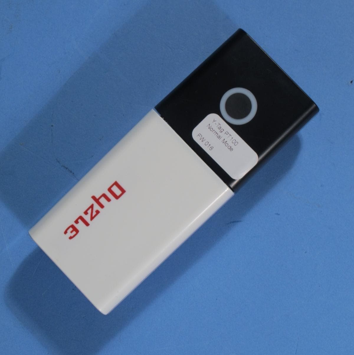
2ADBY0201501
Aug 23, 2015Battery operated wireless PT100 temperature unit
Equipment Class
DXX - Part 15 Low Power Communication Device Transmitter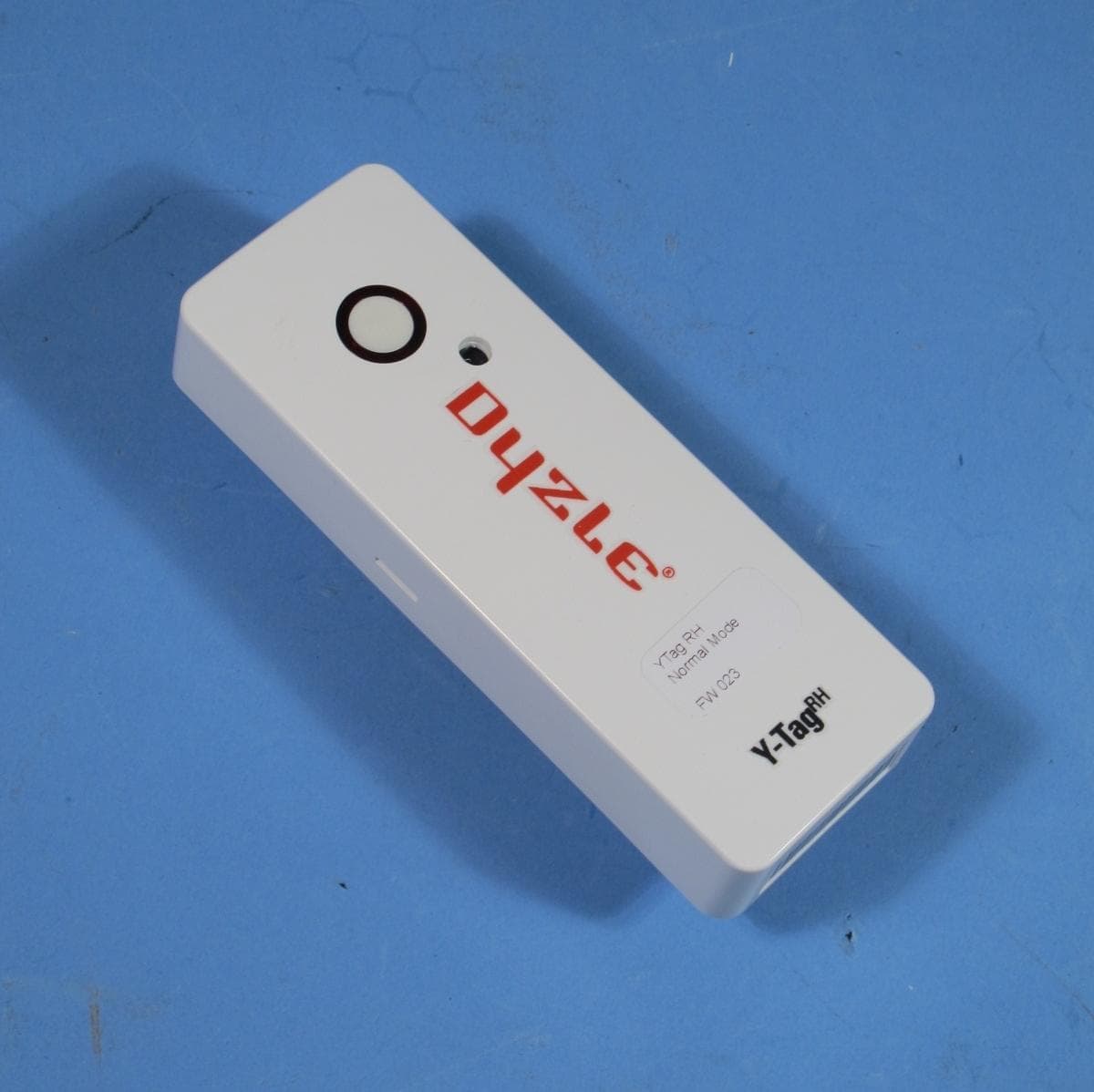
2ADBY0401003
Aug 23, 2015Battery operated wireless humidity unit
Equipment Class
DXX - Part 15 Low Power Communication Device Transmitter
2ADBY0101701
Jul 16, 2015Y-Gate 3.0 Base Station
Equipment Class
DXX - Part 15 Low Power Communication Device Transmitter