2ADCMODGR-6802.11 b/g/n, Bluetooth 2.0 + EDR, GPS/GLONASS enabled Augmentation Eyewear
Osterhout Design Group
Click to zoom
Application Details
- Equipment Class
- DSS - Part 15 Spread Spectrum Transmitter
- Date of Grant
- Dec 16, 2014
- Application Purpose
- Original Equipment
- Date of Application
- Dec 16, 2014
- Equipment Note
- 802.11 b/g/n, Bluetooth 2.0 + EDR, GPS/GLONASS enabled Augmentation Eyewear
- Frequency Range
- 2402.00000000 - 2480.00000000
- Company
- Osterhout Design Group
- Country
- United States
Documents & Files
Document Text
Text extracted from the exhibit documents filed with the FCC. Open a document above to read the original.
Users Manual
1 USER GUIDE R-6 GLASSES 2 Osterhout Design Group (ODG) reserves exclusive rights to the product and grants not other licenses, rights, or data of any kind. ODG prohibits the reverse engineering or deconstruction of the item for any other purpose. SDK documentation, guides, user forums, and software downloads can be accessed through the ReticleOS Developer Center: To request a Developer account, please send an email to [email protected]. developer.osterhoutgroup.com DEVELOPER SUPPORT R-6 GLASSES 3 Your ODG R-6 device has been designed and manufactured to stringent quality and safety standards. You should, however, be aware of the following important precautions for safe use of the glasses and accessories. Warning: This device contains powerful magnets and should be kept a distance from persons with any metallic, electronic, or magnetic device implants in the body. This device contains lithium ion batteries, which can explode or cause burns if disassembled or exposed to fire or high heat. Batteries must be disposed and recycled safely and properly. Safety & Care Read all of these instructions carefully. Keep these instructions for future reference. Heed all warnings. Clean only with dry cloth. Only use attachments/accessories specified by ODG. Do not store glasses near any heat sources such as radiators, registers, stoves, amplifiers or other items that produce heat. 4 Quick Start ....................................................................................5 Included in the Kit ..................................................................6-7 Main Components ..................................................................8-9 Using the Track Pad .................................................................10 Charging ......................................................................................11 Earbuds .......................................................................................12 Head Strap .................................................................................12 Wireless Finger Controller ...................................................13 Launching Applications .........................................................14 Control Panel ............................................................................15 System Menu .............................................................................15 Nose Bridge ...............................................................................16 Storing the Glasses ..................................................................17 Parts & Accessories .................................................................18 Table of Contents 5 Unpack Glasses Attach Accessories Adjust Fit Power Up Launch Applications • Remove the glasses from the compact storage case. • Unfold the ear horn. See Page 18 • If audio is desired, attach Ear Buds. See Page 12 • Attach Head Strap if needed. See Page 12 • Adjust Nose Bridge height and/or swap nose pads if needed for optimum comfort and display viewing angle. See Page 17 • Press and release the Power button to turn on the glasses. Within 30 seconds a startup screen should appear and then the Home Screen. If there is insufficient power to boot the device, see Charging , Page 11. • Power up the Wireless Finger Controller by inserting it’s battery and then pressing the two small round buttons at the same time. See Page 13 • Power up the Wireless Keyboard by turning the power switch on. See Page 14 • When the system powers on, the Home Screen will appear with a row of icons mid-screen. Swipe left or right on the Track Pad to highlight an application, and then press the Track Pad to launch it. See Page 15 Quick Start 1 2 3 4 5 6 Included in the Kit R-6 GLASSES WIRELESS FINGER CONTROLLER WIRELESS FINGER CONTROLLER BATTERY WIRELESS FINGER CONTROLLER USB CHARGER (2) EAR BUDS PROTECTIVE CASE USB POWER ADAPTOR 7 USER GUIDE MICROFIBER LENS CLEANING CLOTH HEAD STRAP MAGNETIC USB DATA & POWER CABLE 8 Track Pad Finger Swipe ........................................................Controls cursor/selector Press down ...........................................................Click/select Power Button Short Press, Device Off ...................................Powers up device Short Press, Device On ...................................Puts displays to sleep 2-3 Second Press ...............................................Displays Shutdown menu 10 Second press .................................................Forces shutdown of system Back Button Short Press ...........................................................Navigates to previous screen Long Press ............................................................Navigates to Home Screen Short Press, Home Screen .............................Displays or Hides Home Screen Menu Button Short Press ...........................................................Navigates to previous screen Long Press ............................................................Navigates to Home Screen Short Press, Home Screen .............................Displays or Hides Home Screen RIGHT SIDE VIEW POWER BUTTON BACK BUTTON TRACK PAD/CLICK VIBRATORY FEEDBACK MENU BUTTON MAGNETIC EARBUD PORT Main Controls 9 FRONT VIEW TOP VIEW MAGNETIC DATA & POWER PORT CAMERA TRACK PAD/CLICK NOSE BRIDGE SHIELDS EAR HORNS TEMPLES 10 RIGHT TEMPLE, TOP PRESS DOWN TO SELECT SWIPE TO MOVE CURSOR Using the Track Pad The track pads located on top of the right temple of the glasses as well as the Wireless Finger Controller are optical devices. They function equally with gloveless and gloved fingers. Track Pad: Finger Swipe ..............................................Controls cursor/selector Press down .................................................Click/select TRACK PAD/CLICK 11 To charge the glasses, attach the Magnetic USB Data & Power Cable to the charging port on top of the left temple and plug the cable into the supplied power supply. A charging status light …
Text truncated - open the document above for the full version.
Cover Letter(s)
153 Townsend Street, San Francisco, CA 94107 (415) 644-4000 www.osterhoutgroup.com Re: Request to remove documents from all public access Osterhout Design Group (ODG) 153 Townsend Street Suite 570 San Francisco, CA 94107 Attention: Federal Communications Commission Regarding FCC ID: 2ADCMODGR-6 Hello, As per §§ 0.457(d) and 0.459 of FCC Rules, ODG requests the FCC, as the authority, remove the documentation below from public access. This application is for Long Term Confidentiality. The documents are currently publicly available. This information is a trade secret. These are ODG confidential documents. Failure to do so will result in great financial hardship to ODG as these documents can help the competition reverse engineer our product. Access to them by our competitors will cause great harm FCC ID: 2ADCMODGR-6 Please remove exhibits from public access: Long Term Confidentiality Exhibit Description Exhibit Type Antenna Description Operational Description Antenna Specification Operational Description Block Diagram Block Diagram Parts List Parts List/Tune Up Info Schematics Schematics Technical Description Operational Description Sincerely, Michael Gbadebo President
External Photos
Applicant: Osterhout Design Group Report No.20140924‐01 R‐6 Glasses_FCC Prepared By: ITC Engineering Services, Inc. 9959 Calaveras Road, PO Box 543 Sunol, California 94586‐0543 Tel: +1(925) 862‐2944 Fax: +1(925) 862‐9013 Email: [email protected] Web: www.itcemc.com Page 56 of 57 Product: R‐6 Glasses 16.1 EUT TECHNICAL SPECIFICATIONS Manufacturer: Osterhout Design Group General Description: The R‐6 Smart Glasses offers immersive 3D HD viewing of stored or streaming video content, with stereo audio, in a static setting, or in a head orientation tracking augmented vision mode. EUT Name: Smart Glasses Model: R‐6 Dimensions: 15mm x 17mm x 5.5mm Serial Number: Operating Frequency: 2.400 GHz‐ 2.4835 GHz Power Cord Type: Shielded Un‐Shielded 16.2 EUT PHOTOS FIGURE 63: Front Oblique View Applicant: Osterhout Design Group Report No.20140924‐01 R‐6 Glasses_FCC Prepared By: ITC Engineering Services, Inc. 9959 Calaveras Road, PO Box 543 Sunol, California 94586‐0543 Tel: +1(925) 862‐2944 Fax: +1(925) 862‐9013 Email: [email protected] Web: www.itcemc.com Page 57 of 57 Product: R‐6 Glasses FIGURE 64: Rear Oblique View
ID Label/Location Info
LEFT INNER FRAME LEFT TEMPLE INSIDE FRONT Assembled in USA FCC ID: 2ADCMODGR-6 R612345
Internal Photos
Front Internal Photos Back Front
RF Exposure Info
802 N. Twin Oaks Valley Road, Suite 105 • San Marcos, CA 92069 • U.S.A. TEL (760) 471-2100 • FAX (760) 471-2121 http://www.rfexposurelab.com CERTIFICATE OF COMPLIANCE SAR EVALUATION Osterhout Design Group Dates of Test: December 12, 2014 153 Townsend St., Suite 570 Test Report Number: SAR.20141205 San Francisco, CA 94107 Revision A This wireless mobile and/or portable device has been shown to be compliant for localized specific absorption rate (SAR) for uncontrolled environment/general exposure limits specified in ANSI/IEEE Std. C95.1-1992 and had been tested in accordance with the measurement procedures specified in IEEE 1528-2013 and IEC 62209-2:2010 (See test report). I attest to the accuracy of the data. All measurements were performed by myself or were made under my supervision and are correct to the best of my knowledge and belief. I assume full responsibility for the completeness of these measurements and vouch for the qualifications of all persons taking them. RF Exposure Lab, LLC certifies that no party to this application is subject to a denial of Federal benefits that includes FCC benefits pursuant to Section 5301 of the Anti-Drug Abuse Act of 1988, 21 U.S.C. 853(a). Jay M. Moulton Vice President Testing Cert. # 2387.01 FCC ID: 2ADCMODGR-6 Model(s): R-6 Test Sample: Engineering Unit Same as Production Serial Number: 00073 Equipment Type: Wireless Glasses Classification: Portable Transmitter Next to Face TX Frequency Range: 2412 – 2462 MHz Frequency Tolerance: ± 2.5 ppm Maximum RF Output: 2450 MHz (b) – 19.89 dB (0.097 W), 2450 MHz (g) – 19.77 dB (0.095 W), 2450 MHz (n20) – 19.73 dB (0.094 W), 2450 MHz (n40) – 19.75 dB (0.094 W) Average Conducted Power Signal Modulation: DSSS, OFDM Antenna Type: Internal Antenna Application Type: Certification FCC Rule Parts: Part 2, 15C, 15E KDB Test Methodology: KDB 447498 D01 v05r02, KDB 248227 v01r02 Industry Canada: RSS-102, Safety Code 6 Maximum SAR Value: 0.14 W/kg Reported Simultaneous SAR: 0.18 W/kg Reported Separation Distance: 0 mm © 2014 RF Exposure Lab, LLC This report shall not be reproduced except in full without the written approval of RF Exposure Lab, LLC. Report Number: SAR.20141205 Table of Contents 1. Introduction ........................................................................................................................ 3 SAR Definition [5] ................................................................................................................... 4 2. SAR Measurement Setup ................................................................................................... 5 Robotic System ...................................................................................................................... 5 System Hardware ................................................................................................................... 5 System Electronics ................................................................................................................. 6 Probe Measurement System .................................................................................................. 6 3. Probe and Dipole Calibration .............................................................................................14 4. Phantom & Simulating Tissue Specifications .....................................................................15 Head & Body Simulating Mixture Characterization ................................................................15 5. ANSI/IEEE C95.1 – 1992 RF Exposure Limits [2] ..............................................................16 Uncontrolled Environment .....................................................................................................16 Controlled Environment .........................................................................................................16 6. Measurement Uncertainty .................................................................................................17 7. System Validation..............................................................................................................18 Tissue Verification .................................................................................................................18 Test System Verification ........................................................................................................18 8. SAR Test Data Summary ..................................................................................................19 Procedures Used To Establish Test Signal ...........................................................................19 Device Test Condition ...........................................................................................................19 SAR Data Summary – 2450 MHz Body 802.11b ...................................................................22 SAR Data Summary – Simultaneous Evaluation ...................................................................23 9. Test Equipment List ...........................................................................................................24 10. Conclusion ....................................................................................................................25 11. References ....................................................................................................................26 Appendix A – System Validation Plots and Data .......................................................................27 Appendix B – SAR Test Data Plots ...........................................................................................30 Appendix C – SAR Test Setup Photos ......................................................................................32 Appendix D – Probe Calibration Data Sheets ............................................................................39 Appendix E – Dipole Calibration Data Sheets ................................................................…
Text truncated - open the document above for the full version.
RF Exposure Info
This SAR Exclusion Threshold applies to the subject device for certification. Reference TIMCO Job #2088UC14
Test Report
Test Report issued under the responsibility of: ITC ENGINEERING SERVICES, INC. FCC CFR Title 47 Part 15 Subpart C 15.205, 15.209, 15.247 Report Reference No. ............... : 20140924-01R1 R-6 Glasses_FCC Date of Issue ................................ : November 11, 2014 Total Number of Pages ................ : 57 Testing Laboratory .................... : ITC Engineering Services, Inc. Address ........................................ : 9959 Calaveras Road, Box 543, Sunol CA 94586 Applicant’s Name ..................... : Osterhout Design Group Address ........................................ : 153 Townsend Street, Suite 570, San Francisco, CA USA 94107 Contact ........................................ : Mr. Brian Donnelly Phone ........................................... : 415-644-4000 Fax ................................................ : 415-644-4039 Test Specification Standard ....... : FCC CFR Title 47 Part 15 Subpart C 15.205, 15.209, 15.247 Test Procedure ............................ : ANSI C63.4:2009, ANSI C63.10:2009 (Test Procedures) & Public Notice DA 00-705:2000 Judgment ..................................... : Complies Test Item Description................ : 802.11 b/g/n, Bluetooth 2.0 + EDR, GPS/GLONASS enabled Augmentation Eyewear Manufacturer Logo ...................... : Manufacturer .............................. : Osterhout Design Group Model/Type Reference ................ : R-6 Glasses RF Operating Frequency Band ..... : 2.400 - 2.4835 GHz ISO/IEC 17025:2005 Accredited Laboratory Applicant: Osterhout Design Group Report No.20140924-01R1 R-6 Glasses_FCC Prepared By: ITC Engineering Services, Inc. 9959 Calaveras Road, PO Box 543 Sunol, California 94586-0543 Tel: +1(925) 862-2944 Fax: +1(925) 862-9013 Email: [email protected] Web: www.itcemc.com Page 2 of 57 Product: R-6 Glasses TABLE OF CONTENTS 1 DOCUMENTATION ......................................................................................................................................................... 6 1.1 TESTING LOCATION ........................................................................................................................................................... 6 1.2 REVISION HISTORY ............................................................................................................................................................ 6 1.3 DECLARATION/DISCLAIMER .............................................................................................................................................. 7 1.4 CONDITION OF EUT ........................................................................................................................................................... 7 1.5 GENERAL DESCRIPTION OF EUT ........................................................................................................................................ 7 1.6 OPERATIONAL DESCRIPTION OF EUT ................................................................................................................................ 7 1.7 LIST OF APPLICANT PERIPHERALS/SUPPORTING EQUIPMENT USED DURING TEST ......................................................... 8 1.8 GENERAL TEST REMARKS .................................................................................................................................................. 8 1.9 SUMMARY OF TESTS ......................................................................................................................................................... 8 1.10 MEASUREMENT UNCERTAINTY ........................................................................................................................................ 9 1.11 TEST SET UP PHOTOS ........................................................................................................................................................ 9 2 RADIATED EMISSIONS PER FCC PART 15.209 ................................................................................................................ 11 2.1 ADMINISTRATIVE AND ENVIRONMENTAL DETAILS ........................................................................................................ 11 2.2 TEST EQUIPMENT ............................................................................................................................................................ 11 2.3 TEST SET UP PHOTO(S) .................................................................................................................................................... 11 2.4 LIMITS/REQUIREMENTS .................................................................................................................................................. 12 2.5 TEST DESCRIPTION AND PROCEDURE ............................................................................................................................. 12 2.6 TEST DATA PLOTS ............................................................................................................................................................ 12 3 CONDUCTED POWER LINE EMISSIONS PER FCC PART 15.207 ....................................................................................... 15 3.1 ADMINISTRATIVE AND ENVIRONMENTAL DETAILS ........................................................................................................ 15 3.2 TEST EQUIPMENT ............................................................................................................................................................ 15 3.3 TEST SET UP PHOTO(S) .................................................................................................................................................... 15 3.4 LIMITS/REQUIREMENTS .................................................................................................................................................. 16 3.5 TEST DESCRIPTION AND PROCEDURE .................................................................…
Text truncated - open the document above for the full version.
Test Setup Photos
Osterhout Design Group FCC CFR Title 47 Part 15 Subpart C 15.205, 15.209, 15.247, Testing Test Setup Photos Conducted RF Test Setup RE Test Setup - Active Loop Antenna RE Test Setup - Biconical Antenna - Log Periodic Antenna RE Test Setup - Horn Antennas CE Test Setup - Front View - Side View
Contact Information
Applicant
Michael Gbadebo
Test Firm
ITC Engineering Services, Inc.Michael Gbadebo
Technical Specifications
| # | Rule Parts | Frequency Range | Power Output |
|---|---|---|---|
| 1 | 15C | 2.40 GHz - 2.48 GHz | 6.00 mW |
Other Applications from Osterhout Design Group
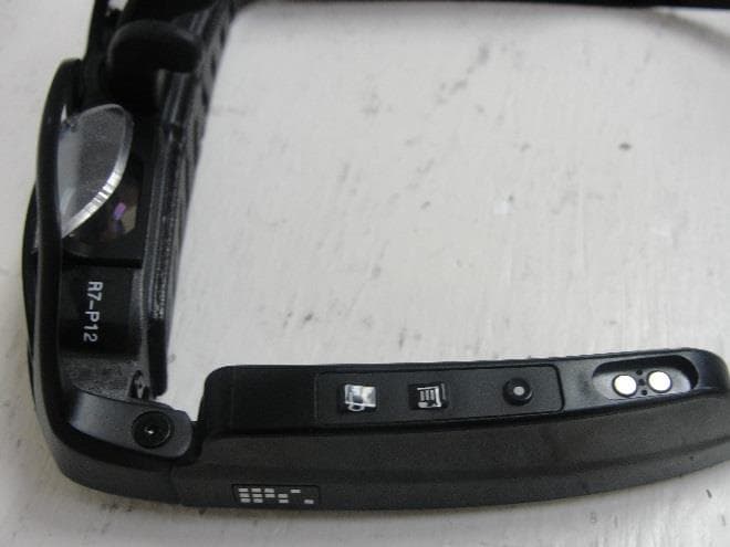
2ADCMR7
Jan 24, 2016802.11b/g/n Bluetooth Smart, 802.11n (5GHz), GPS/GLONASS enabled
Equipment Class
NII - Unlicensed National Information Infrastructure TX
2ADCMRSM1
Jan 24, 2016Bluetooth Smart
Equipment Class
DTS - Digital Transmission System