2ADCMRSM1Bluetooth Smart
Osterhout Design Group
Click to zoom
Application Details
- Equipment Class
- DTS - Digital Transmission System
- Date of Grant
- Jan 24, 2016
- Application Purpose
- Original Equipment
- Date of Application
- Jan 24, 2016
- Equipment Note
- Bluetooth Smart
- Frequency Range
- 2402.00000000 - 2480.00000000
- Company
- Osterhout Design Group
- Country
- United States
Documents & Files
Document Text
Text extracted from the exhibit documents filed with the FCC. Open a document above to read the original.
Users Manual
1 USER GUIDE R-7 SMART GLASSES 2 R-7 User Guide Rev 1.1.1 Nov 2015 ODG Part #: 580-00016 3 Thank you for purchasing the world’s first fully integrated, 3D, see-through, mobile computing eye wear. This User Guide is available for download on the ODG Support website below. It can also be found on the glasses within the Gallery application under PDF Documents . Welcome For questions, additional information not found within this guide, or to open a support ticket visit our Support site: Documentation and development guidance can be accessed through the ReticleOS Developer Center: support.osterhoutgroup.com developer.osterhoutgroup.com Customer Support Developer Support 4 Your ODG R-7 device has been designed and manufactured to stringent quality and safety standards. You should, however, be aware of the follow- ing important precautions for the safe use of the glasses and accessories. Warning: This device contains magnets and should be kept at a distance from persons with any metallic, electronic, or magnetic device implants in the body. This device contains lithium ion batteries, which can explode or cause burns if disassembled or exposed to fire or high heat. Batteries must be disposed and recycled safely and properly. If battery swelling or deformation occurs immediately stop using the device. Read and heed all of these instructions and warnings carefully. This is a Class B product. In a domestic environment, this product may cause radio interference in which case the user may be required to take adequate measures. The design and manufacture of ODG R-7 Glasses is in accordance with the requirements set out in Article 4 of RoHS2 Directive 2011/65/EU. See Page 21 for additional important notices and disclaimers. Keep these instructions for future reference. Clean only with dry microfiber cloth, supplied. Only use attachments/accessories specified by ODG. Do not store glasses near any heat sources such as radiators, registers, stoves, vehicle interiors, amplifiers or other items that produce heat. Safety & Care 5 Welcome ..............................................3 Safety & Care .......................................4 Table of Contents ................................5 Included in the Kit ................................6 Features Overview ...............................7 Main Controls ...................................8-9 Track Pad ...........................................10 Input Modes .......................................10 System Menu .....................................11 Status Bar ..........................................11 Launcher ......................................12-13 Reticle Speed Mouse ...................14-16 Earbuds..............................................17 Head Strap .........................................17 Charging ............................................18 Cleaning .............................................19 Corrective Lenses ..............................19 Technical Specifications ....................20 Important Notices ..............................21 Table of Contents 6 R-7 SMART GLASSES RETICLE SPEED MOUSE USB POWER ADAPTER USER GUIDE HEAD STRAP LENS CLEANING CLOTH 2 EAR BUDS MAGNETIC USB DATA & POWER CABLE USB TO MICRO-USB RETICLE SPEED MOUSE CHARGING CABLE STORAGE CASE INCLUDED IN THE KIT 7 front view top view CONTROLS SHIELDS VIBRATION FEEDBACK VIBRATION FEEDBACK CAMERA TRACK PAD TRACK PAD TEMPLES MAGNETIC USB DATA & POWER PORT FEATURES OVERVIEW 8 Decrease Volume One Step Continually Decrease Volume Hold Increase Volume One Step Continually Increase Volume Hold VOLUME DOWN VOLUME UP Power On Displays On/Off (When device is off) (When device is on) 2 sec Display Shutdown Menu 12 sec Force Shutdown POWER left temple MAIN CONTROLS 9 Display System Menu Previous Screen Switch/Select Open Apps Go to Launcher 3 sec x 2 MENU BACK MULTI-FUNCTION (Default Setting) Toggle Input Mode: Cursor/Selector The multi-function button can be set to perform various commands. To customize this button, go to Settings > Reticle > Temple Buttons bottom view right temple 10 TRACK PAD The track pad is located on top of the right temple of the glasses as well as the Reticle Speed Mouse are input devices that allow the user to control the software interface by swiping with a fin- gertip. It is an optical device that functions equally with gloved or gloveless fingers. Pressing down on a track pad represents a click or selects an item. There are two modes of Track Pad input to allow optimized control for each application. To switch modes, either press the Multi-function button to toggle modes (See Main Controls, Page 8-9). If the Multi-function button has been re-assigned press Menu once to display the System Menu, then select Input Mode. Swiping the Track Pad allows free movement of the cursor in any direction in the same manner as a computer mouse. Swiping the Track Pad up, down, left, or right selects the next button, item, or element in the same man- ner as 4-way arrow keys. CURSOR MODE SELECTOR MODE TRACK PAD INPUT MODES right temple, top 11 SYSTEM MENU Pressing the Menu button once will display the System Menu, providing access to frequently used features and settings. Icons at the top of the menu will launch the Calculator, Flashlight, Clock/Timer, or Camera apps. Notifications displays a list of any current system Notifications. System Settings takes the user to the full Android Settings. Volume, Brightness, Display and Input Mode will display quick controls to adjust these settings. Located at the top of the screen, the Status Bar indicates the status of a variety of elements such as date & time, battery strength, connectivity, and notifications. STATUS BAR 12 The Launcher is the home screen of ReticleOS and will appear when the glasses power up. To return to the Launcher from an application, press the Back button repeatedly until the Launcher is reached. Press and hold the Back button for 3 seconds then release to go to the Launcher at any time. The Laun…
Text truncated - open the document above for the full version.
Users Manual
The Customer agree to add the information on the manual on page 21 of the manual FCC Part 15.19 Warning Statement THIS DEVICE COMPLIES WITH PART 15 OF THE FCC RULES. OPERATION IS SUBJECT TO THE FOLLOWING TWO CONDITIONS: (1) THIS DEVICE MAY NOT CAUSE HARMFUL INTERFERENCE, AND (2) THIS DEVICE MUST ACCEPT ANY INTERFERENCE RECEIVED, INCLUDING INTERFERENCE THAT MAY CAUSE UNDESIRED OPERATION. FCC Part 15.21 Warning Statement The user manual for an intentional or unintentional radiator shall caution the user that causes or modifications not expressly approved by the party responsible for compliance could void the user’s authority to operate the equipment. Glasses & RSM NOTE: THE GRANTEE IS NOT RESPONSIBLE FOR ANY CHANGES OR MODIFICATIONS NOT EXPRESSLY APPROVED BY THE PARTY RESPONSIBLE FOR COMPLIANCE. SUCH MODIFICATIONS COULD VOID THE USER’S AUTHORITY TO OPERATE THE EQUIPMENT.
External Photos
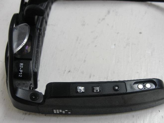
EUT PHOTOS EUT Side View EUT Bottom View
Internal Photos
1.1 EUT PHOTOS Transceiver Top View Transceiver Bottom View Figure 1: Battery Top View Figure 2: Battery Bottom View
Test Report
Test Report Issued Under the Responsibility of: ITC ENGINEERING SERVICES, INC. FCC CFR Title 47 Part 15 Subpart C 15.205, 15.209, 15.247 Report Reference No. .......................... : 20151015-01 Reticle_Speed_Mouse_FCC Date of Issue .......................................... : 12/16/2015 Total Number of Pages .......................... : 27 Testing Laboratory .............................. : ITC Engineering Services, Inc. Address .................................................. : 9959 Calaveras Road, Box 543, Sunol CA 94586 Applicant’s Name ................................ : Osterhout Design Group Address .................................................. : 153 Townsend Street, Suite 570, San Francisco, CA USA 94107 Contact .................................................. : Mr. Brian Donnelly Phone..................................................... : 415-644-4000 Fax ......................................................... : 415-644-4039 Test Specification Standard ................. : FCC CFR Title 47 Part 15 Subpart C 15.205, 15.209, 15.247 Test Procedure ...................................... : KDB 558074 D01 DTS Meas Guidance v03r04 &ANSI C63.4:2009, ANSI C63.10:2009 (Test Procedures) Judgment ............................................... : Complies as Tested Test Item Description .......................... : Bluetooth Smart (No EDR) Finger Controller for R-7 Glasses Manufacturer Logo ................................ : Manufacturer ........................................ : Osterhout Design Group Model/Type Reference .......................... : Reticle Speed Mouse RF Operating Frequency Band ............... : 2.402- 2.48 GHz ISO/IEC 17025:2005 Accredited Laboratory Applicant: Osterhout Design Group Report No.20151015-01- RSM Product: Reticle Speed Mouse Prepared by: ITC Engineering Services, Inc. 9959 Calaveras Road, PO Box 543 Sunol, CA 94586-0543 Template Created by Omid Almasi 1/10/2015 Tel: +1(925) 862-2944 Fax: +1(925) 862-9013 Email: [email protected] Web: www.itcemc.com Page 2 of 27 Table of Contents LIST OF FIGURES ..................................................................................................................................................................... 4 1 DOCUMENTATION ........................................................................................................................................................ 5 1.1 Testing Location ............................................................................................................................................................... 5 1.2 DECLARATION/DISCLAIMER ............................................................................................................................................. 5 1.3 Revision History ............................................................................................................................................................... 5 1.4 Condition Of EUT ............................................................................................................................................................. 6 1.5 General description of EUT .............................................................................................................................................. 6 1.6 Operational description of EUT........................................................................................................................................ 6 1.7 List of Applicant Peripheral/Supporting Equipment Used During Test ............................................................................ 6 1.8 General Test Remarks ...................................................................................................................................................... 6 1.9 Summary of Tests ............................................................................................................................................................ 7 1.10 Measurement Uncertainty .............................................................................................................................................. 7 1.11 Test Set up Photos ........................................................................................................................................................... 7 2 RADIATED EMISSIONS PER FCC PART 15.209 ................................................................................................................. 9 2.1 Administrative and Environmental Details ...................................................................................................................... 9 2.2 Test Equipment ................................................................................................................................................................ 9 2.3 Test Set up Photo(s) ......................................................................................................................................................... 9 2.4 Limits/Requirements ....................................................................................................................................................... 9 2.5 Test Description and Procedure ....................................................................................................................................... 9 2.6 Test Data Tables ............................................................................................................................................................ 10 2.7 Test Data Plots ............................................................................................................................................................... 11 3 CONDUCTED POWER LINE EMISSIONS PER FCC PART 15.207– BLUETOOTH SMART .................................................... 13 3.1 Administrative and Environmental Details ....................................................................................…
Text truncated - open the document above for the full version.
Test Setup Photos
1.1 TEST SET UP PHOTOS FIGURE 1: Conducted RF Test Setup FIGURE 2: Conducted Emission test setup FIGURE 3: RE Test Setup - Active Loop Antenna FIGURE 4: RE Test Setup – Biconical Horizontal FIGURE 5: RE Test Setup – Biconical Vertical FIGURE 6:RE Test Setup- Log Periodic Horizontal FIGURE 7:RE Test Setup-Log Periodic Vertical
Contact Information
Applicant
Michael Gbadebo
Test Firm
ITC Engineering Services, Inc.Michael Gbadebo
Technical Specifications
| # | Rule Parts | Frequency Range | Power Output |
|---|---|---|---|
| 1 | 15C | 2.40 GHz - 2.48 GHz | 212.00 µW |
Other Applications from Osterhout Design Group
2ADCMR7
Jan 24, 2016802.11b/g/n Bluetooth Smart, 802.11n (5GHz), GPS/GLONASS enabled
Equipment Class
NII - Unlicensed National Information Infrastructure TX
2ADCMODGR-6
Dec 16, 2014802.11 b/g/n, Bluetooth 2.0 + EDR, GPS/GLONASS enabled Augmentation Eyewear
Equipment Class
DSS - Part 15 Spread Spectrum Transmitter