2ADH9WOWLCR1Wireless Light Switch Receiver Load Controller
Levven Automation Inc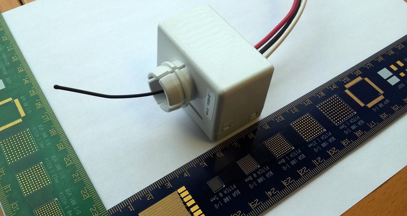
Click to zoom
Application Details
- Equipment Class
- CYY - Communications Receiver used w/Pt 15 Transmitter
- Date of Grant
- Feb 18, 2015
- Application Purpose
- Original Equipment
- Date of Application
- Oct 30, 2014
- Equipment Note
- Wireless Light Switch Receiver Load Controller
- Frequency Range
- 917.00000000 - 917.00000000
- Company
- Levven Automation Inc
- Country
- Canada
Documents & Files
Document Text
Text extracted from the exhibit documents filed with the FCC. Open a document above to read the original.
Users Manual
Levven Automation Inc. 9741 - 54th Ave NW, Edmonton Alberta, Canada T6E 5J4 Phone: (780) 391-3000 Fax: (780) 391-3001 1-9 Wireless Light Switch User Manual (Draft) 1 System description The wireless light switch system is designed to wireless turn lights on or off from anyway in a house, which contains two components: switch and controller. The Switch is a thin, wall mount switch that looks and feels much like a normal decora switch and fits in a normal decora faceplate. It is battery-powered and transmits commands in a secured way to controllers when a user pushes a button. The Controller is an action component that receives commands from remote switches and takes action accordingly. It is installed in the junction box to a lighting fixture connected with phase, neutral and control wires. The switch to controller can be point to point (one switch controlling one controller) or multi point to multi point (multi switches signaling one or more controllers). Levven Automation Inc. 9741 - 54th Ave NW, Edmonton Alberta, Canada T6E 5J4 Phone: (780) 391-3000 Fax: (780) 391-3001 2-9 2 Specifications 2.1 Switch 1. Dimensions......................................................................................105mmx36mmx11.2mm 2. Battery............................................................................................................................CR2032 3. Wireless frequency.......................................................................................................917Mhz 4. Wireless range..................................................................Up to 100 meters line of sight 5. Operating Temperature.........................................................................................0-40°C 6. Indoor use only 2.2 Controller 1. Dimensions......................................................................................56mmx47.7mmx39.6mm 2. Voltage................................................................................................................120VAC, 60Hz 3. Maximum load..................................................................................................................600W 4. Wireless frequency.......................................................................................................917Mhz 5. Wireless range..................................................................Up to 100 meters line of sight 6. Operating temperature.........................................................................................0-40°C 7. Load type.....................................Incandescent, halogen and other resistive light fixtures Levven Automation Inc. 9741 - 54th Ave NW, Edmonton Alberta, Canada T6E 5J4 Phone: (780) 391-3000 Fax: (780) 391-3001 3-9 8. Indoor use only 3 Features Compatible for incandescent, halogen and other resistive light fixtures Non-relayable wireless lighting control On-Off controller Battery powered switch operable up to 10 years* Ease of multiple-way control o Each switch can control as many as possible controllers, as long as they are within the wireless range o Each controller controllable by up to 10 switches Advanced security level o Rolling code to prevent repeat attack o 128-bit encryption Ease of installation (No wiring between controller and switch, and a switch can be attached to anywhere) Switch dimmer function ready *Conditions apply: typical operation 100 switches per day, average 0.5 second press and hold time, 20°C. Actual battery life greatly depends on usage environment, such as temperature and humidity, and operation conditions, such as press and hold time. 4 Installation Instructions WARNINGS: • To be installed and/or used in accordance with local electrical codes and regulations. • The controller should be mounted to a listed electrical junction box of suitable size with height no less than 2” (50.8mm) and with ½” knockouts, such as ⁄ Octagonal box. • If you are unsure about any part of these instructions, consult a qualified electrician. NOTE: Use check boxes when Steps are completed. Step 1 WARNING: TO AVOID FIRE SHOCK OR DEATH; TURN OFF POWER at circuit breaker or fuse and test that power is off before wiring! Step 2 Identifying your wiring application, these wires in a junction box are needed 1. Line/hot 2. Neutral Levven Automation Inc. 9741 - 54th Ave NW, Edmonton Alberta, Canada T6E 5J4 Phone: (780) 391-3000 Fax: (780) 391-3001 4-9 3. Load (to light fixture) Step 3 Mount the controller inside a suitable junction box: The controller is normally installed inside a junction box that supports light fixtures. Insert its connector coupling into a ½” knockout from inside, with the antenna stretching out from the hole as well. Levven Automation Inc. 9741 - 54th Ave NW, Edmonton Alberta, Canada T6E 5J4 Phone: (780) 391-3000 Fax: (780) 391-3001 5-9 Step 4 Wiring controller: Connect (Neutral) wire from junction box to white wire on controller Connect (Line/hot) wire from junction box to black wire on controller Connect (Load) wire from junction box to red wire on controller Step 5 Power on the controller The green LED on the controller will be lit The red LED will indicate controller status: it is on indicating the circuit to the light fixture is connected; it is off indicating the circuit to the light fixture is disconnected Step 6 Pairing switch with controller: On the controller, press “PAIR” button. The LED on the controller will begin flash green slowly NOTE: If there is no pairing request received within 60 seconds, the controller will quit the pairing procedure and the LED will go back to solid status automatically Press both switch buttons. You may need to push hard to let them contact the bottom of the switch. When it is activated, the LED on the controller will begin flash green and red rapidly Press “PAIR” on the controller again to confirm the pairing. The LED will flash green rapidly for a while to indicate success, then stop flashin…
Text truncated - open the document above for the full version.
Block Diagram
11 22 33 44 55 66 D D C C B B A A 1 2 E12010 5.00.1018/03/2014Controller_Block Diagram.SchDoc Size: Date:File:Rev: Sheet: of 11x17 Controller block diagram Wireless Light Switch Project:Designed By: Yi (Tony) Dong Client: 9741 - 54 Ave.Edmonton, AlbertaCanada, T6E 5J4 Levven Automations STM8S003 MCU LEDs Indicators Switches 30MHz Si4355 Receiver SPI 3.3V Relay Capacitor-Resistor Power supply DC-DC converter 12V 3.3V Wire antenna Load Line Neutral 120V AC, 60Hz ~ 3.3V 12V
Cover Letter(s)
Levven Automation Inc. 9741 54 Ave NW Edmonton, AB T6E 5J4 Canada Phone: (780) 391-3000 Fax: (780) 391-3001 Confidential Letter October 31, 2014 Federal Communications Commission Authorization and Evaluation Division Confidentiality Request Pursuant to Sections 0.457 and 0.459 of the Commission’s Rules, the Applicant Hereby requests confidential treatment of information accompanying this application as outlined below: 1. Block Diagram 2. Circuit Diagram 3. Operational Description The above materials contain trade secrets and proprietary information not customarily released to the public. The public disclosure of these matters might be harmful to the Applicant and provide unjustified benefits to its competitors. The Applicant understands that pursuant to Rule 0.457, disclosure of this Application and all accompanying documentation will not be made before the date of the Grant for this application. Sincerely, Applicant’s company name: Levven Automation Inc. Applicant’s company address: 9741 54 Ave NW Edmonton, AB T6E 5J4 Canada _____________________________ Jim Qualie [email protected] (780) 391-3000
Cover Letter(s)
Levven Automation Inc. 9741 54 Ave NW Edmonton, AB T6E 5J4 Canada Phone: (780) 391-3000 Fax: (780) 391-3001 Confidential Letter October 31, 2014 Federal Communications Commission Authorization and Evaluation Division Confidentiality Request Pursuant to Sections 0.457 and 0.459 of the Commission’s Rules, the Applicant Hereby requests confidential treatment of information accompanying this application as outlined below: 1. Block Diagram 2. Circuit Diagram 3. Operational Description The above materials contain trade secrets and proprietary information not customarily released to the public. The public disclosure of these matters might be harmful to the Applicant and provide unjustified benefits to its competitors. The Applicant understands that pursuant to Rule 0.457, disclosure of this Application and all accompanying documentation will not be made before the date of the Grant for this application. Sincerely, Applicant’s company name: Levven Automation Inc. Applicant’s company address: 9741 54 Ave NW Edmonton, AB T6E 5J4 Canada _____________________________ Jim Qualie [email protected] (780) 391-3000 Nov 7, 2014
External Photos
External photos (GoWoW Controller) 1 1. Front view 2. Rear view 3. Oblique view External photos (GoWoW Controller) 2
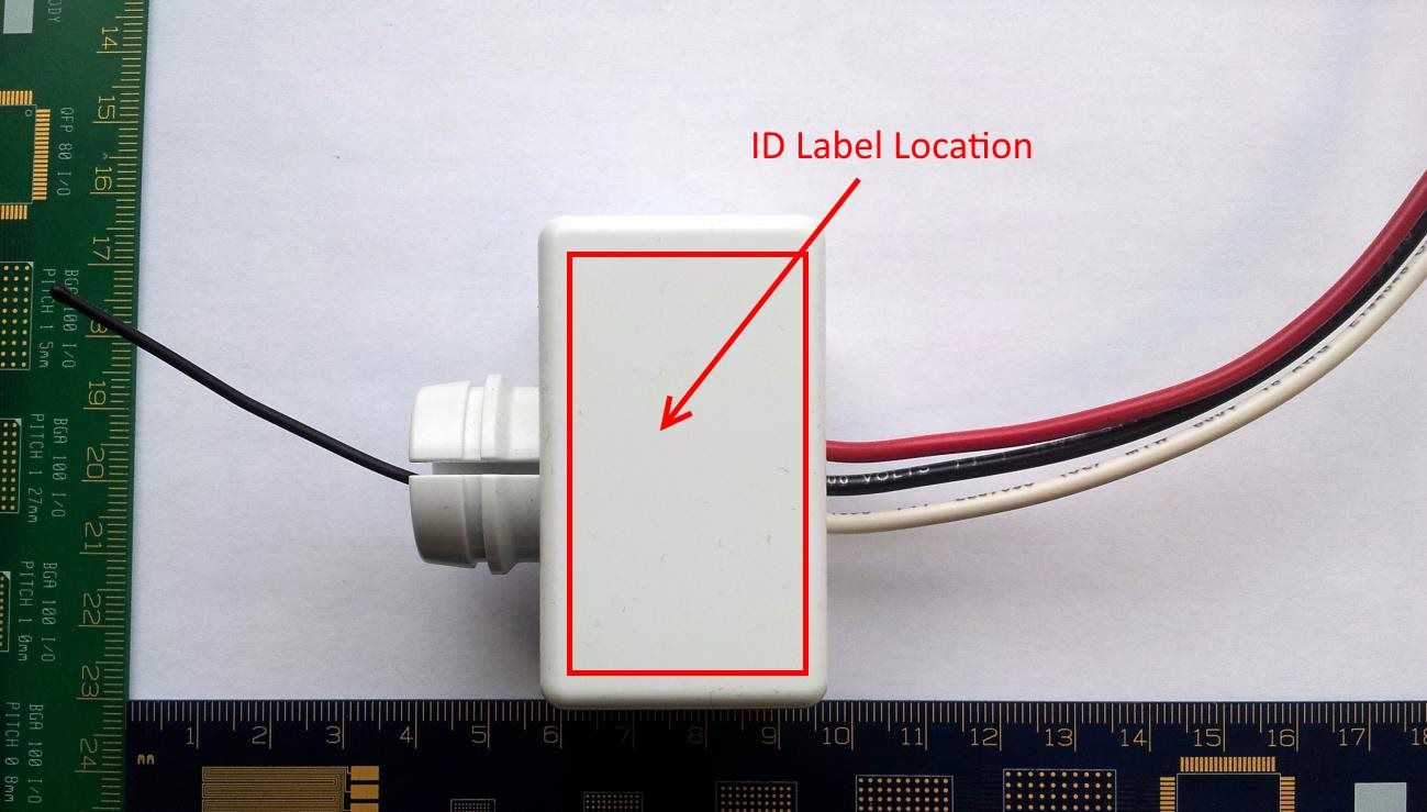
ID Label/Location Info
Brand/TBD The/switch/without/wires A/product/by Item/. LOAD/CONTROLLER http:- - levven,com Rating: °F4 VAC S4Hz S44W for incandescentW halogen and other resistive lightings, Indoor use only, Operating temperature range 4f54°C, FCC ID:/FADHqWOWLCR° IC ID:/°F539AfWOWLCR° Date of manufacture: Certified to CSA Std, CFF,F No, °5 Conforms to UL F55A Risk of electric shockW do not open, No user serviceable parts insideW refer servicing to qualified personnel,
Internal Photos
Internal photos (GoWoW Controller) 1 1. Internal photo 2. Top view Internal photos (GoWoW Controller) 2 3. Bottom view
Test Report
This report is for the exclusive use of Intertek's Client and is provided pursuant to the agreement between Intertek and its Client. Intertek's responsibility and liability are limited to the terms and conditions of the agreement. Intertek assumes no liability to any party, other than to the Client in accordance with the agreement, for any loss, expense or damage occasioned by the use of this report. Only the Client is authorized to permit copying or distribution of this report and then only in its entirety. Any use of the Intertek name or one of its marks for the sale or advertisement of the tested material, product or service must first be approved in writing by Intertek. The observations and test results in this report are relevant only to the sample tested. This report by itself does not imply that the material, product, or service is or has ever been under an Intertek certification program. Non-Specific EMC Report Shell Rev. July 2013 Page 1 of 16 Levven Electronics Ltd. GoWow Load Controller EMC TEST REPORT Report Number: 101624281ATL-004b Project Number: G101624281 Report Issue Date: June 30, 2014 Product Designation: GoWow Load Controller Standards: CFR47 FCC Part 15 Subpart B:2014 Section 15.107, 15.109 Industry Canada RSS-GEN Issue 3 December 2010 Tested by: Client: Intertek Testing Services NA, Inc. 1950 Evergreen Blvd, Suite 100 Duluth, GA 30096 USA Levven Electronics Ltd. 9741 54 Avenue Edmonton AB T6E 5J4 Canada Report prepared by Report reviewed by Mary Sampson/Senior Project Engineer Bryan Taylor/CE Team Leader Intertek Report Number: 101624281ATL-004b Issued: 06/30/2014 Non-Specific EMC Report Shell Rev. July 2013 Page 2 of 16 Levven Electronics Ltd Load Controller 1 Introduction and Conclusion The tests indicated in section 2.0 were performed on the product constructed as described in section 4.0. The remaining test sections are the verbatim text from the actual data sheets used during the investigation. These test sections include the test name, the specified test Method, a list of the actual Test Equipment Used, documentation Photos, Results and raw Data. No additions, deviations, or exclusions have been made from the standard(s) unless specifically noted. Based on the results of our investigation, we have concluded the product tested complies with the requirements of the standard(s) indicated. The results obtained in this test report pertain only to the item(s) tested. 2 Test Summary Section Test full name Result 3 Client Information 4 Description of Equipment Under Test 5 System Setup and Method 6 Receiver Spurious Radiated Emissions (CFR47 FCC Part 15 Subpart B:2014 Section 15.109 Industry Canada RSS-GEN Issue 3 December 2010, Section 6.1) Pass 7 AC Mains Conducted Emissions Pass 8 Revision History Intertek Report Number: 101624281ATL-004b Issued: 06/30/2014 Non-Specific EMC Report Shell Rev. July 2013 Page 3 of 16 Levven Electronics Ltd Load Controller 3 Client Information This EUT was tested at the request of: Client: Levven Electronics Ltd. 9741 54 Avenue Edmonton AB T6E 5J4 CAN Contact: Jim Qualie Telephone: (780) 391-3004 Fax: Not provided Email: [email protected] 4 Description of Equipment Under Test Manufacturer: Levven Automation Inc 9741-54 th Ave NW Edmonton, AB T6E 5J4 Canada Equipment Under Test Description Manufacturer Model Number Serial Number Controller Levven Automation Inc Load Controller Intertek Assigned ID: ATL1405221559-004 Receive Date: 05/22/2014 Received Condition: Good Type: Production Description of Equipment Under Test (provided by client) The Controller is an action component that receives commands from remote switches and takes action accordingly. It is installed in the junction box to a lighting fixture connected with phase, neutral and control wires. It does not transmit any signals. The switch to controller can be point to point (one switch controlling one controller) or multi point to multi point (multi switches signaling one or more controllers). Equipment Under Test Power Configuration Rated Voltage Maximum Load Rated Frequency Number of Phases 120 Vac 600 W 60 Hz 1 Operating modes of the EUT: No. Descriptions of EUT Exercising 1 Continuous Receive mode Software used by the EUT: No. Descriptions of EUT Exercising 1 When powered on, the EUT enters an infinite loop to continuously monitor button actions and wireless signal receiving. If there is an event happened, such as a button pressed or a new wireless package received, it goes to related handling processes to take action or to give response. Intertek Report Number: 101624281ATL-004b Issued: 06/30/2014 Non-Specific EMC Report Shell Rev. July 2013 Page 4 of 16 Levven Electronics Ltd Load Controller 5 System Setup and Method Cables ID Description Length (m) Shielding Ferrites Termination A Power Cable .1 No No Light Fixture B Power Cable 1.9 No No AC Mains Support Equipment Description Manufacturer Model Number Serial Number Light Fixture None known None known None known 5.1 Method: Configuration as required by ANSI C63.4-2009, CFR47 FCC Part 15 Subpart B:2014 Section 15.107, 15.109, and Industry Canada RSS-GEN Issue 3 December 2010. 5.2 EUT Block Diagram: (A) Power cable (B) AC Mains EUT Light Fixture Intertek Report Number: 101624281ATL-004b Issued: 06/30/2014 Non-Specific EMC Report Shell Rev. July 2013 Page 5 of 16 Levven Electronics Ltd Load Controller 6 Receiver Spurious Radiated Emissions 6.1 Method Tests are performed in accordance with CFR47 FCC Part 15 Subpart B:2014 Section 15.109 and Industry Canada RSS-GEN Issue 3 December 2010, Section 6.1. TEST SITE: 10m Semi-Anechoic Chamber 10 Meter Semi-Anechoic Chamber The test site for radiated emissions is located at 1950 Evergreen Blvd, Suite 100, Duluth, Georgia 30096. It is a 10 meter semi-anechoic chamber manufactured by Panashield. Embedded in the floor is a 3 meter diameter turntable. Measurement Uncertainty For radiated emissions, lab U(3.9 dB at 3m and 3.6 dB at 10m below 1 GHz, and 4.2 dB at 3m above 1 GHz) < CISPR …
Text truncated - open the document above for the full version.
Contact Information
Applicant
Jim Qualie(Owner)
Technical Contact
Non-Technical Contact
Levven Automation IncJames Keirstead
[email protected]7803913000
Test Firm
Intertek Testing Services NA Inc.Charles Parker
Technical Specifications
| # | Rule Parts | Frequency Range | Power Output | Tolerance |
|---|---|---|---|---|
| 1 | 15B | 917 MHz - 917 MHz | 0.00 µW | ppm |
Other Applications from Levven Automation Inc
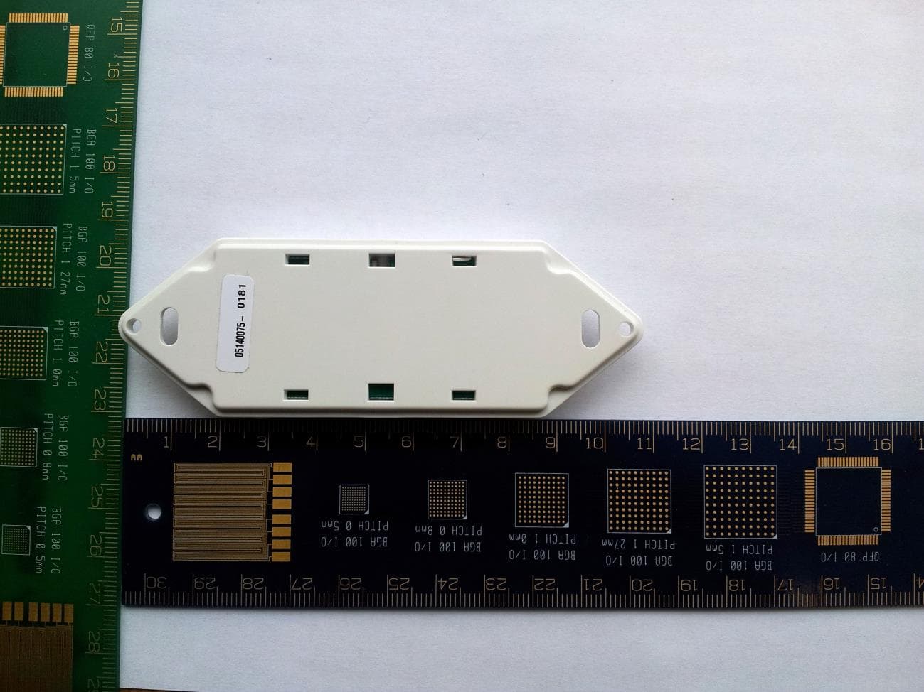
2ADH9WOWSW1
Feb 18, 2015Wireless Light Switch Transmitter
Equipment Class
DXX - Part 15 Low Power Communication Device Transmitter