2ADJKJMA-610Marine Radar
ALPHATRON MARINE USA, INC.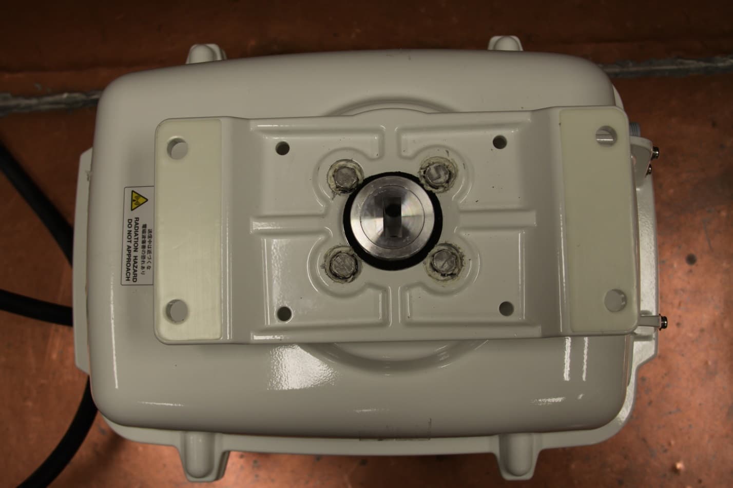
Click to zoom
Application Details
- Equipment Class
- MRD - Marine Radar
- Date of Grant
- Jun 04, 2015
- Application Purpose
- Original Equipment
- Date of Application
- Jun 04, 2015
- Equipment Note
- Marine Radar
- Frequency Range
- 9300.00000000 - 9500.00000000
- Company
- ALPHATRON MARINE USA, INC.
- Country
- United States
Documents & Files
Document Text
Text extracted from the exhibit documents filed with the FCC. Open a document above to read the original.
Users Manual
SECTION 3 BASIC OPERATION 3.1 FLOW OPERATION..................................................................................... 3-1 3.1.1 POWER ON AND START THE SYSTEM .................................................... 3-2 3.1.2 OBSERVE AND ADJUST VIDEO ................................................................ 3-3 3.1.3 ACQUIRE AND MEASURE DATA............................................................... 3-3 3.1.4 END THE OPERATION AND STOP THE SYSTEM .................................... 3-4 3.2 MENU COMPOSITION ................................................................................ 3-5 3.3 PREPARATION............................................................................................ 3-9 3.3.1 ADJUST DISPLAY BRILLIANCE [BRILL] .................................................. 3-9 3.3.2 ADJUST OPERATION PANEL BRILLIANCE [PANEL] .............................. 3-9 3.3.3 SWITCH DAY/NIGHT MODE [DAY/NIGHT] ................................................ 3-9 3.3.4 ADJUST BRILLIANCE OF INFORMATION ON RADAR DISPLAY (BRILLIANCE SETTING)........................................................................... 3-10 3.3.5 ADJUST SOUND VOLUME (BUZZER VOLUME)..................................... 3-10 3.3.6 RESET ALARM BUZZER [ALARM ACK] ................................................. 3-11 3.3.7 SET DISPLAY COLOR .............................................................................. 3-11 3.4 BASIC OPERATIONS................................................................................ 3-12 3.4.1 START TRANSMISSION [TX] ................................................................... 3-12 3.4.2 STOP TRANSMISSION [STBY] ................................................................ 3-12 3.4.3 CHANGE RANGE (OBSERVATION RANGE SCALE) [+RANGE-] .......... 3-13 3.4.4 TUNE ......................................................................................................... 3-13 3.4.5 CONTROL SENSITIVITY [GAIN] .............................................................. 3-14 3.4.6 SUPPRESS SEA CLUTTER [SEA] ........................................................... 3-14 3.4.7 SUPPRESS RAIN/SNOW CLUTTER [RAIN] ............................................ 3-15 3.4.8 REJECT RADAR INTERFERENCE [IR] ................................................... 3-16 3.4.9 HIDE/DISPLAY RANGE RINGS (RINGS).................................................. 3-16 3.4.10 HIDE SHIP’S HEADING LINE (HL OFF) ................................................... 3-17 3.5 GENERAL OPERATIONS ......................................................................... 3-18 3.5.1 MOVE CROSS CURSOR MARK BY TRACKBALL .................................. 3-18 3.5.2 USE EBLS (ELECTRONIC BEARING LINES) [EBL1/EBL2] ................... 3-18 3.5.3 USE VRMS (VARIABLE RANGE MARKERS) [VRM1/VRM2] .................. 3-20 3.5.4 USE P-LINES (PARALLEL INDEX LINES) [P-LINE] ................................ 3-22 3.5.5 MOVE OWN SHIP’S DISPLAY POSITION [OFF CENT] ........................... 3-23 3.5.6 DISPLAY OTHER SHIPS’ TRAILS [TRAILS] ............................................ 3-23 3.5.7 DISPLAY OWN VECTOR [OWN VECT] .................................................... 3-25 3.5.8 EDITING OWN MARK ............................................................................... 3-26 3.5.9 TIME ZONE SETTING ............................................................................... 3-34 3.5.10 LOCAL TIME SETTING ............................................................................. 3-35 3.5.11 CHANGE THE UNIT OF RATE OF TURN ................................................. 3-36 3.5.12 DISPLAY AIS LABEL ................................................................................ 3-37 3.5.13 ECHO EXPANSION SWITCH .................................................................... 3-37 3.6 DISAPLAY USER MAP.............................................................................. 3-38 3.6.1 EDIT USER MAP ....................................................................................... 3-38 3.6.2 CORRECT POSITION ON USER MAP (SHIFT )....................................... 3-41 3.6.3 CORRECT POSITION ON USER MAP (SHIFT CLEAR). ......................... 3-41 3.6.4 SET USER MAP DISPLAY (MARK DISPLAY SETTING).......................... 3-42 3.6.5 OPERATE USER MAP FILE (FILE OPERATIONS) .................................. 3-52 3.7 SCREEN CAPTURE .................................................................................. 3-63 3.7.1 SCREEN CAPTURE SETTING (SELECT CARD SLOT). ......................... 3-63 3.7.2 SCREEN CAPTURE SETTING (SAVE FILE). ........................................... 3-65 3.7.3 SCREEN CAPTURE SETTING (ERASE FILE). ........................................ 3-66 3.7.4 SCREEN CAPTURE SETTING (AUTO CAPTURE). ................................. 3-67 3.7.5 SCREEN CAPTURE SETTING (AUTO CAPTURE MODE). ..................... 3-68 3.7.6 SCREEN CAPTURE SETTING (AUTO CAPTURE INTERVAL). .............. 3-69 3.7.7 SCREEN CAPTURE SETTING (AUTO FILE ERASE). ............................. 3-70 3.7.8 SCREEN CAPTURE SETTING (MANUAL CAPTURE)............................. 3-71 3.8 USER SETTING......................................................................................... 3-72 3.8.1 USER SETTING (LOAD USER SETTING). ............................................... 3-72 3.8.2 USER SETTING (SAVE USER SETTING)................................................. 3-73 3.8.3 USER SETTING (ERASE USER SETTING).............................................. 3-74 3.9 FORMAT CARD ......................................................................................... 3-75 3.9.1 FORMAT CARD (SELECT CARD SLOT).................................................. 3-75 3.10 AIS FUNCTION.......................................................................................... 3-76 3.10.1 VESSEL NAME LIST ................................................................................. 3-76 3.10.2 VESSEL INF…
Text truncated - open the document above for the full version.
Users Manual
SECTION 7 TROUBLE SHOOTING 7.1 Fault Finding.................................................. 7-3 7.2 Trouble Shooting........................................... 7-4 7.3 Replacement of Major Parts ......................... 7-6 7-1 WARNING Never carry out internal inspection or repair work of the equipment by users. Inspection or repair work by unauthorized personnel may result in fire hazard or electric shock. Ask the nearest branch, business office or a dealer for inspection and repair. Turn off the main power before maintenance work. Otherwise, an electric shock may result. Turn off the main power before cleaning the equipment. Especially, make sure to turn off the indicator if a rectifier is used. Otherwise, equipment failure, or death or serious injury due to electric shock may result, because voltage is outputted from the rectifier even when the radar is not operating. For operating the radar equipment in the good conditions, it is necessary to make the maintenance work as described below. If maintenance is made properly, troubles will reduce. It is recommended to make regular maintenance work. Common points of maintenance for each unit are as follow: Clean the equipment. Remove the dust, dirt, and sea water rest on the equipment cabinet with a piece of dry cloth. Especially, clean the air vents with a brush for good ventilation. 7-2 7. TROUBLE SHOOTING yyy yyyy 7 WARNING Turn off the main power source before starting maintenance. Otherwise, an electric shock or injury may be caused. Turn off the main power if you need to be near the scanner unit for maintenance or inspection purposes. Direct exposure to electromagnetic waves at close range in death or serious injury. Set the safety switch for stopping the scanner unit to the OFF position. Otherwise, an accidental contact with the rotating scanner unit may cause injury. 7-3 7.1 FAULT FINDING In case of semiconductor circuits, it is deemed that there are few cases in which the used semiconductor devices have inferior quality or performance deterioration except due to insufficient design or inspection or by other external and artificial causes. In general, the relatively many causes are disconnection in a high-value resistor due to moisture, a defective variable resistor and poor contact of a switch or relay. Some troubles are caused by defective parts, imperfect adjustment (such as tuning adjustment) or insufficient service (such as poor cable contact). It will also be effective to check and readjust these points. Melted fuses are caused by any clear cause. When a fuse is replaced, it is necessary to check the related circuits even if there is no trouble. In checking, note that there is some dispersion in the fusing characteristics. Table 7-1 shows a lit of alarm message displayed on the screen. Table 7-1 Alarm message list ALARM TYPE MASSAGE REASON TRX(SSW OFF) SCANNER SAFETY SWITCH OFF TRX(AZI) SCANNER azimuth pulse error TRX(MHV) TRANSMITTER high voltage error TRX(TRIGGER) TRANSMITTER trigger error PANEL CONTROL PANEL communication error DOCKING No docking data GPS No GPS input GPS(DATA) GPS data error GPS(STATUS) GPS status error PROC(INT) PROCESSOR interrupt error PROC(AZI) PROCESSOR detects no azimuth pulse PROC(HL) PROCESSOR detects no heading pulse PROC(REVERSE) PROCESSOR detects SCANNER rotating in reverse. ASIC1 TO RADAR Interrupt, form ASIC1 to RADA, error PROC(VIDEO) PROCESSOR detects no radar video. PROC(TRIGGER) PROCESSOR detects no trigger COM1 Serial port 1 error COM2 Serial port 2 error COM3 Serial port 3 error COM4 Serial port 4 error HEADING No heading data DEPTH No depth data DEPTH(DATA) Depth data error FAN Fan error RUDDER No rudder data AUTOPILOT No autopilot data ROT No rate of turn data SYSTEM FAILURE TRIP No trip data CAN’T TRANSMIT Attempted to select TRANSMIT while it is not allowed. NO HEADING DATASHM OFFSET attempted with no heading data. NOT ALLOWED Function attempted while not allowed. GENERAL WARNING POSN RESET L/L sentence is switched. Table 7-2 shows a list of fuses used in the equipment. Table 7-2 Fuse List Location Parts No.Current RatingProtection Circuit Type Transmitter-receiver UnitF401 5A Scanner unit without motorST4-5AN1 Motor Unit F402 8A Motor (CBP-169) ST6-8AN1 7-4 7.2 TROUBLE SHOOTING yyy yyyy 7 7.2 TROUBLE SHOOTING As this radar equipment includes complicated circuits, it is necessary to request a specialist engineer for repair or instructions for remedy if any circuit is defective. There are also troubles by the following causes, which should be referred to in checking or repair work. 1 Poor Contact in Terminal Board of Inter-Unit Cables a) Poor contact in terminal board b) The cable end is not fully connected, that it, contacted with earthed another terminal. c) Disconnected cable wire 2 Poor Contact of Connector within Unit Reference: This radar equipment is provided with 7-3 standard spares. Table 7-3 Spares (7ZXRD0020, JMA-610) 7ZXRD0020 Name Type/Code Shape (mm) In useSpare Parts No. Location Fuse ST4-5AN1 (5ZFCA00050) 1 3 F401 Inside processing unit Fuse ST6-8AN1 (5ZFCA00052) 1 3 F402 Inside processing unit Table 7-4 Special Parts [I] JMA-610-7 Parts No. Name Type Manufacturer Location Code V101 Magnetron MSF11562B NewJRC Scanner 5VMAA???? A101 Circulator FCX68R Toshiba Scanner 6AJRD00001 A102 Diode Limiter NJS6930 NewJRC Scanner 5EZAA00024 31.8 Φ6.35 31.8 Φ6.35 7-5 Table 7-5 Circuit Block to be Repaired (JMA-610) Location Circuit Block Type Remarks Scanner Motor with gear CBP-169 DC brush less motor (ordinary) Scanner Modulator CPA-276-1 Excluding Magnetron Scanner Receiver NRG-237 Scanner Power supply circuit CBD-1783 Scanner Terminal board circuit CQD-2186 Scanner Revolwtior coutrol circuit Scanner Filter circuit CFR-193R Processor Radar processing circuit CDC-1371 Processor Terminal board circuit CQD-2185 Processor Power circuit CBD-1655 Processor DC-DC convertor CBD-1701 Operation panel unit Operation circuit CCK-892A Operation panel unit Track ball CHG-198 7-6 7.3 REPLACE…
Text truncated - open the document above for the full version.
Users Manual
RIVER RADAR EQUIPMENT INSTRUCTION MANUAL - i - PREFACE Thank you very much for purchasing the JRC marine radar equipment, JMA-610. This equipment is a river radar equipment designed to obtain safe operation of ships. This equipment consists of a radar signal processing unit, a LCD display unit and a scanner unit as its main units. ● Before operating the equipment, be sure to read this instruction manual carefully for correct operation. ● Maintain this instruction manual so that operators can refer to it at anytime. Refer to this manual when any inconvenience or defect occurs. - ii - ●BEFORE OPERATION● Pictorial Indication Various pictorial indications are included in this manual and are shown on these equipment so that you can operate them safety and correctly and prevent any danger to you and/or to other persons and any damage to your property during operation. Such indications and their meanings are as follows. Please understand them before you read this manual: DANGER This indication is shown where incorrect equipment operation due to negligence may cause death or serious injuries. WARNING This indication is shown where any person is supposed to be in danger of being killed or seriously injured if this indication is neglected and these equipment are not operated correctly. CAUTION This indication is shown where any person is supposed to be injured or any property damage is supposed to occur if this indication is neglected and these equipment are not operated correctly. Examples of Pictorial Indication Electric Shock The U mark represents CAUTION (including DANGER and WARNING). Detailed contents of CAUTION (“Electric Shock” in the example on the left.) is shown in the mark. Disassembling Prohibited The ; mark represents prohibition. Detailed contents of the prohibited action (“Disassembling Prohibited” in the example on the left.) is shown in the mark. Disconnect the power plug The z mark represents instruction. Detailed contents of the instruction (“Disconnect the power plug “ in the example on the left.) is shown in the mark. Warning Label There is a warning label on the top cover of the equipment. Do not try to remove, break or modify the label. - iii - Never conduct inspection or repair work of equipment components. Inspection or repair work by uncertified personnel may result in fire hazard or electrocution. For inspection and repair work of equipment components, consult with our branch office, branch shop, sales office, or our distributor in your district. When conducting maintenance, make sure to turn the main power off. Failure to comply may result in electrocution. Turn off the main power before cleaning the equipment. Especially when a rectifier is used, make sure to turn it off since voltage is still outputted from the rectifier even after the indicator and the radar are turned off. Failure to comply may result in equipment failure, or death or serious injury due to electric shock. When conducting maintenance work on the antenna, make sure to turn its main power off. Failure to comply may result in electrocution or injuries. Make sure to turn off the antenna operation switch. Failure to comply may result in injuries caused by physical contact with the rotating antenna. ●PRECAUTIONS● DANGER - iv - WARNING Never carry out internal inspection or repair work of the equipment by users. Inspection or repair work by unauthorized personnel may result in fire hazard or electric shock. Ask the nearest branch, business office or a dealer for inspection and repair. Turn off the main power before maintenance work. Otherwise, an electric shock may result. Turn off the main power before cleaning the equipment. Especially, make sure to turn off the indicator if a rectifier is used. Otherwise, equipment failure, or death or serious injury due to electric shock may result, because voltage is outputted from the rectifier even when the radar is not operating. Turn off the main power if you need to be near the scanner unit for maintenance or inspection purposes. Direct exposure to electromagnetic waves at close range in death or serious injury. Turn off the main power source before starting maintenance. Otherwise, an electric shock or injury may be caused. When conducting maintenance work, make sure to turn off the power and unplug the power line of the processor so that the power supply to the equipment is completely cut off. Some equipment components can carry electrical current even after the power switch is turned off, and conducting maintenance work without unplugging the power connector may result in electrocution, equipment failure, or accidents. - v - Set the safety switch for stopping the scanner unit to the OFF position. Otherwise, an accidental contact with the rotating scanner unit may cause injury. Turn off the main power source before starting maintenance. Otherwise, an electric shock or injury may be caused. Turn off the main power if you need to be near the scanner unit for maintenance or inspection purposes. Direct exposure to electromagnetic waves at close range in death or serious injury. WARNING When cleaning the screen, do not wipe it too strongly with a dry cloth. Also, do not use gasoline or thinner to clean the screen. Otherwise the screen surface may be damaged. Never carry out internal inspection or repair work of the equipment by users. Inspection or repair work by unauthorized personnel may result in fire hazard or electric shock. Ask the nearest branch, business office or a dealer for inspection and repair. Turn off the main power before maintenance work. Otherwise, an electric shock may result. Turn off the main power before cleaning the equipment. Especially, make sure to turn off the indicator if a rectifier is used. Otherwise, equipment failure, or death or serious injury due to electric shock may result, because voltage is outputted from the rectifier even when the radar is not operating. - vi - Set the safety switch for stopping the scanner unit to the OFF posi…
Text truncated - open the document above for the full version.
External Photos
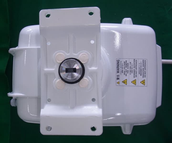
APPLICANT: ALPHATRON MARINE USA, INC. IC: 2ADJKJMA-610 EXTERNAL PHOTOS: TOP BOTTOM FRONT BACK LEFT SIDE RIGHT SIDE
ID Label/Location Info
Processor unit JMA‐610 radar. With location of the approval label for the USA and Canada
Internal Photos
JMA‐610, river radar pictures from the Scanner unit. JMA‐610 radar, top unit Transceiver unit JMA‐610, mounted inside the top unit. Terminal board CQD‐2186 Motor Drive Modulator, NCM‐883 Power supply CBD‐1783
RF Exposure Info
RF Exposure Evaluation Report APPLICANT ALPHATRON MARINE USA, INC. 1205 BUTLER ROAD LEAGUE CITY TX 77573 USA FCC ID 2ADJKJMA-610 MODEL NUMBER JMA-610 PRODUCT DESCRIPTION MARINE RADAR STANDARD APPLIED CFR 47 Part 2.1091 PREPARED BY Christian Pawlak We, TIMCO ENGINEERING, INC. would like to declare that the device has been evaluated in accordance with 47 CFR Part 2.1091 and meets the requirements. The attached report shall not be reproduced except in full without the written approval of TIMCO ENGINEERING, INC. 849 NW STATE ROAD 45 NEWBERRY, FL 32669 USA PH: 888.472.2424 OR 352.472.5500 FAX: 352.472.2030 EMAIL: [email protected] HTTP://WWW.TIMCOENGR.COM Applicant: ALPHATRON MARINE USA, INC. FCC ID: 2ADJKJMA-610 Report: V:\A\ALPHATRON\45AUT15\45AUT15RF EXP MPE RPT.DOCX Page 2 of 4 GENERAL REMARKS Attestations This equipment has been evaluated in accordance with the standards identified in this report. To the best of my knowledge and belief, these evaluations were performed using the procedures described in this report. I attest that the necessary evaluations were made, under my supervision, at: Timco Engineering Inc. 849 NW State Road 45 Newberry, Fl 32669 Authorized Signatory Name: Christian Pawlak Engineering Project Manager Date: 5/31/2015 RF Exposure Requirements General information Device type: MARINE RADAR Devices that operate under Part 90 of this chapter are subject to RF exposure evaluation prior to equipment authorization or use. Antenna The manufacturer does not specify an antenna, but a typical antenna has a gain of 0 dBi. Configuration Antenna p/n Type Max. Gain (dBi) Fixed mounted Any omni 0 Operating configuration and exposure conditions: The conducted output power is shown in the table below. Typical use qualifies for a maximum duty cycle factor of 100%. Operation: A typical installation consists of an antenna system with a 10 meter coaxial cable of the type RG 213/ U type which has a loss as follows; Nom. Attenuation for RG 213/U: Frequency MHz Attenuation per 100ft. dB 1 .27 10 .55 50 1.3 100 1.9 200 2.7 400 4.1 700 6.5 900 7.6 1000 8.0 4000 21.5 MPE Calculation: The minimum separation distance is calculated as follows: Applicant: ALPHATRON MARINE USA, INC. FCC ID: 2ADJKJMA-610 Report: a\Alphatron\45AUT15\45AUT15TestReport.docx The limit for general uncontrolled exposure environment is shown in FCC rule Part 1.11310, Table 1. Max Power 4900 Wequals Max Power 4900000mW Duty Cycle0.06% equalsDuty Factor 0.0006numeric Antenna Gain30.2dBiequals Gain numeric1047.129 numeric Coax Loss0 dBGain - Coax Loss1047.129 numeric Power Density1 mW/cm 2 Frequency9500MHzFrequency rangPower denEnter this value MHz mW/cm 2 mW/cm 2 0.3-1.34100100 1.34-30 180/f 2 0.0 30-3000.20.2 300-1,500f/1500 6.3 1,500-100,0001 1 f = frequency in MHz Minimum Separation Distance495cm4.95m Minimum Seperation in Inches194.7166Inches Minimum Separation Distance for Mobile or Fixed Devices General Population/Uncontrolled Exposure Insert values in yellow highlighted boxes to determine Minimum Separation Distance Enter power Density from the chart to the rightRule Part 1.1310, Table 1
Test Report
FCC PART 80 RADAR TEST REPORT APPLICANT ALPHATRON MARINE USA, INC. 1205 BUTLER ROAD LEAGUE CITY TX 77573 USA FCC ID 2ADJKJMA-610 MODEL NUMBER JMA-610 PRODUCT DESCRIPTION MARINE RADAR DATE SAMPLE RECEIVED 1/7/2015 DATE TESTED 02/09/2015 – 02/13/2015, 03/20/2015 TESTED BY Christian Pawlak APPROVED BY Sid Sanders TIMCO REPORT NO. 45AUT15TestReport.docx TEST RESULTS PASS FAIL THE ATTACHED REPORT SHALL NOT BE REPRODUCED EXCEPT IN FULL WITHOUT THE WRITTEN APPROVAL OF TIMCO ENGINEERING, INC. 849 NW STATE ROAD 45 NEWBERRY, FL 32669 USA PH: 888.472.2424 OR 352.472.5500 FAX: 352.472.2030 EMAIL: [email protected] HTTP://WWW.TIMCOENGR.COM Applicant: ALPHATRON MARINE USA, INC. FCC ID: 2ADJKJMA-610 Report: a\Alphatron\45AUT15\45AUT15TestReport.docx Page 2 of 21 TABLE OF CONTENTS GENERAL REMARKS ...................................................................................... 3 EUT SPECIFICATION ..................................................................................... 4 TEST SETUP INFORMATION ............................................................................ 4 TEST REPORT SUMMARY ................................................................................ 6 RF POWER OUTPUT ....................................................................................... 7 MODULATION CHARACTERISTICS ................................................................... 8 MODULATION CHARACTERISTICS - SP ..................................................................... 9 MODULATION CHARACTERISTICS - MP1 ................................................................. 10 MODULATION CHARACTERISTICS - MP2 ................................................................. 11 MODULATION CHARACTERISTICS - LP ................................................................... 12 OCCUPIED BANDWIDTH .............................................................................. 13 OCCUPIED BANDWIDTH - SP ................................................................................ 14 OCCUPIED BANDWIDTH – MP1 .............................................................................. 15 OCCUPIED BANDWIDTH - MP2 ............................................................................. 16 OCCUPIED BANDWIDTH - LP ................................................................................. 17 SPURIOUS EMISSIONS AT ANTENNA TERMINALS (CONDUCTED) ....................... 18 FIELD STRENGTH OF SPURIOUS EMISSIONS .................................................. 19 FREQUENCY STABILITY ............................................................................... 20 EQUIPMENT LIST ........................................................................................ 21 Applicant: ALPHATRON MARINE USA, INC. FCC ID: 2ADJKJMA-610 Report: a\Alphatron\45AUT15\45AUT15TestReport.docx Page 3 of 21 GENERAL REMARKS The attached report shall not be reproduced except in full without the written permission of Timco Engineering Inc. The test results relate only to the items tested. Summary The device under test does: fulfill the general approval requirements as identified in this test report not fulfill the general approval requirements as identified in this test report Attestations This equipment has been tested in accordance with the standards identified in this test report. To the best of my knowledge and belief, these tests were performed using the measurement procedures described in this report. All instrumentation and accessories used to test products for compliance to the indicated standards are calibrated regularly in accordance with ISO 17025:2005 requirements. I attest that the necessary measurements were made, under my supervision, at: Timco Engineering Inc. 849 NW State Road 45 Newberry, Fl 32669 Authorized Signatory Name: Christian Pawlak Engineering Project Manager Date: 03/25/2025 Table of Contents Applicant: ALPHATRON MARINE USA, INC. FCC ID: 2ADJKJMA-610 Report: a\Alphatron\45AUT15\45AUT15TestReport.docx Page 4 of 21 EUT SPECIFICATION EUT Description MARINE RADARMARINE RADAR FCC ID 2ADJKJMA-610 Model Number JMA-610 Serial Number N/A Frequency Range 9300-9500 MHz Test Frequency 9410 MHz Type of Emission P0N Modulation Pulsed, no modulation EUT Power Source 110–120Vac/50– 60Hz DC Power (24v) Battery Operated Exclusively Test Item Prototype Pre-Production Production Type of Equipment Fixed Mobile Portable Antenna None TEST SETUP INFORMATION Test facility Timco Engineering, Inc. 849 NW State Road 45, Newberry, FL 32669 Test Condition The EUT was tested under normal temperature and humidity. The temperature was 24-26ºC with a relative humidity of 50-70%. Modifications Using magnetron EEV MG4006 Test Exercise The EUT was placed in continuous transmit mode of operation Applicable Standards ANSI/TIA 603-D:2010, FCC CFR 47 Part 80 Table of Contents Applicant: ALPHATRON MARINE USA, INC. FCC ID: 2ADJKJMA-610 Report: a\Alphatron\45AUT15\45AUT15TestReport.docx Page 5 of 21 SYSTEM DESCRIPTION: Function of this System The JMA-610 series is a color radar system. The main functions include: * Sensitivity adjustment * Sea clutter & rain/snow clutter suppression. * Interference reflector * Bearing & range measurement using a cursor, fixed/variable range markers & electronic bearing line * Targets expansion * trails display * receiving inland AIS sentence * Display of AIS label (vessel name) while pushing the button when the AIS sentence is being received * Delivery of echo’s screen by LAN * Display of user map * Controlling almost function of the radar by PS2 mouse which user connected * Saving the radar screen to the inside or the external memory (Screen capture function) GENERAL SPECIFICATION FOR SCANNER UNIT 1. Dimensions: Height: 458mm, Swing Circle: 2270mm 2. Mass: 36.0 kg 3. Polarization: Horizontal 4. Beam width Horizontal (-3dB): 1.0 degree Vertical (-3dB): 25 degree Side lobe level: Less than -26dB within 10 degree of main beam Less than -30dB outside 10 degree of main beam 5. Rotation speed: 2…
Text truncated - open the document above for the full version.
Contact Information
Applicant
Thomas Scot McCasland(Training Manager)
Technical Contact
Timco Engineering, Inc.Christian Pawlak
[email protected]888-472-2424
849 NW State Road 45 · NEWBERRY, Florida · United States
Non-Technical Contact
Timco Engineering, Inc.Sharon Hoffman
[email protected]888-472-2424
Test Firm
Timco Engineering, Inc.Bruno Clavier
Technical Specifications
| # | Rule Parts | Frequency Range | Power Output | Emission | Tolerance |
|---|---|---|---|---|---|
| 1 | 80 | 9.30 GHz - 9.50 GHz | 4900 W | 235MP0N | 11.6900000000 ppm |
Other Applications from ALPHATRON MARINE USA, INC.
2ADJKNKE387
Jul 07, 2021River Radar
Equipment Class
MRD - Marine Radar
2ADJKJHS-800S
Dec 02, 2020MARINE VHF RADIOTELEPHONE WITH BLUETOOTH
Equipment Class
TNB - Licensed Non-Broadcast Station Transmitter