2ADMF-MD0456ESP32-CAM WiFi Camera Modules
Shenzhen KEYES DIY Robot Co.,Ltd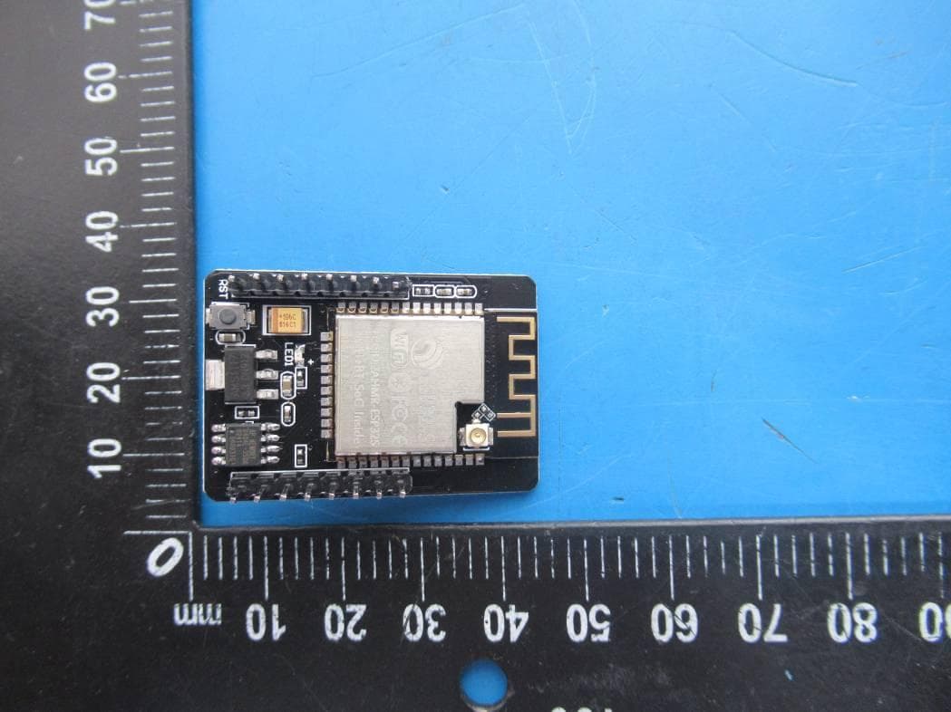
Click to zoom
Application Details
- Equipment Class
- DTS - Digital Transmission System
- Date of Grant
- Feb 17, 2021
- Application Purpose
- Original Equipment
- Date of Application
- Feb 17, 2021
- Equipment Note
- ESP32-CAM WiFi Camera Modules
- Frequency Range
- 2412.00000000 - 2462.00000000
- Country
- China
Documents & Files
Document Text
Text extracted from the exhibit documents filed with the FCC. Open a document above to read the original.
Users Manual
User manual ESP32-CAM Module 1. Features Tiny 802.11b/g/n Wi-Fi Adopt low consumption and dual core CPU as an application processor Main frequency reaches up to 240MHz,and computer power reaches up to 600 DMIPS Built-in 520 KB SRAM,built-out 8MB PSRAM Support UART/SPI/I2C/PWM/ADC/DAC port Support OV2640 and OV7670 camera,with built-in photoflash Support uploading picture via WiFI Support TF card Support multiple sleep modes Embed Lwip and FreeRTOS Support STA/AP/STA+AP working mode Support Smart Config/AirKiss smartconfig Support serial local upgrade and remote firmware upgrade(FOTA) 2. Description ESP32-CAM has the most competitive and tiny camera module of the industrial. As the most tiny system, it can work independently. Its size is 27*40.5*4.5mm, and its deep-sleep current can reach 6mA at least. It can be widely applied to many IoT applications like household smart devices, industrial wireless control, wireless monitoring , QR wireless identification, wireless positioning system signals and other IoT applications, also a really ideal choice. In addition, with DIP sealed package, it can be used by inserting into board, so as to improve rapid productivity, provide high reliability connection method and convenience for all kinds of IoT applications hardware. 3. Specification Module Model ESP32-CAM Sealed package DIP-16 Size 27*40.5*4.5(±0.2)mm SPI Flash Default as 32Mbit RAM Interior 520KB+ exterior 8MB PSRAM Wi-Fi 802.11 b/g/n Support Interface UART、SPI、I2C、PWM Support TF Card Up to 4G IO Port 9 Pcs Serial Rate Default as 115200 bps Picture Output Format JPEG(only OV2640 ),BMP,GRAYSCALE Spectrum Range 2400 ~2483.5MHz Antenna Form On-board PCB antenna , increase 2dBi Transmit Power 802.11b: 14±3 dBm (@11Mbps) 802.11g: 14±3 dBm (@54Mbps) 802.11n: 14±3 dBm (@MCS7) Reception Sensitivity CCK, 1 Mbps : -90dBm CCK, 11 Mbps: -85dBm 6 Mbps (1/2 BPSK): -88dBm 54 Mbps (3/4 64-QAM): -70dBm MCS7 (65 Mbps, 72.2 Mbps): -67dBm Power Consumption Turn off flash light:180mA@5V Turn on flash light and adjust the brightness to the maximum:310mA@5V Deep-sleep: the lowest power consumption reaches 6mA@5V Modern-sleep: the lowest is 20mA@5V Light-sleep: the lowest is 6.7mA@5V Safety WPA/WPA2/WPA2-Enterprise/WPS Power Supply Range 4.75-5.25V Working Temperature -20 °C ~ 70 °C Storage environment -40 °C ~ 125 °C , < 90%RH Weight 10g 4. Picture Output Format Rate of ESP32-CAM Module Format Size QQVGA QVGA VGA SVGA JEG 6 7 7 8 BMP 9 9 - - GRAYSCALE 9 8 - - Test environment: Camera model: OV2640 XCLK:20MHz, module sends picture to browser via WIFI 5. PIN Description CAM ESP32 SD ESP32 D1 PIN5 CLK PIN14 D2 PIN18 CMD PIN15 D3 PIN19 DATA0 PIN2 D4 PIN21 DATA1/photo flash PIN4 D5 PIN36 DATA2 PIN12 D6 PIN39 DATA3 PIN13 D7 PIN34 XCLK PIN35 PCLK PIN0 VSYNC PIN22 HREF PIN25 SDA PIN23 SCL PIN26 POWER PIN PIN27 PIN32 6. Minimal system diagram 7. Contact us Website:www.ai-thinker.com Tel:0755-29162996 Email: [email protected] FCC warning: This equipment has been tested and found to comply with the limits for a Class B digital device, pursuant to part 15 of the FCC Rules. These limits are designed to provide reasonable protection against harmful interference in a residential installation. This equipment generates, uses and can radiate radio frequency energy and, if not installed and used in accordance with the instructions, may cause harmful interference to radio communications. However, there is no guarantee that interference will not occur in a particular installation. If this equipment does cause harmful interference to radio or television reception, which can be determined by turning the equipment off and on, the user is encouraged to try to correct the interference by one or more of the following measures: • Reorient or relocate the receiving antenna. • Increase the separation between the equipment and receiver. • Connect the equipment into an outlet on a circuit different from that to which the receiver is connected. • Consult the dealer or an experienced radio/TV technician for help. Caution: Any changes or modifications to this device not explicitly approved by manufacturer could void your authority to operate this equipment. This device complies with part 15 of the FCC Rules. Operation is subject to the following two conditions: (1) This device may not cause harmful interference, and (2) this device must accept any interference received, including interference that may cause undesired operation. The device has been evaluated to meet general RF exposure requirement. This equipment complies with FCC radiation exposure limits set forth for an uncontrolled environment. This equipment should be installed and operated with minimum distance 20cm between the radiator & your body
Cover Letter(s)
February 4, 2021 Equipment Autorisation Division Federal Communications Commission 7435 Oakland Mills Road Columbia, MD 21046 FCC ID: 2ADMF-MD0456 Product Name: ESP32-CAM WiFi Camera Modules Request for Confidentiality Pursuant to Sections 0.457 and 0.459 of the commissions rules, we hereby request that the following documents be held confidential: (List here the documents for which you are seeking confidentiality – for example ...) Schematics Block diagram Operation description These materials contain trade secrets and proprietary information and are not customarily released to the public. The public disclosure of this information might be harmful to the company and provide unjustified benefits to our competitors. Dated this February 4, 2021 By: Mr Zuo Signature Printed Title: General Manager On behalf of : Shenzhen KEYES DIY Robot Co., Ltd Telephone: +86-0755-23200269
External Photos
FCC ID: 2ADMF-MD0456
ID Label/Location Info
3.0cm x1.0cm FCC ID: 2ADMF-MD0456 Model No.: MD0456
Internal Photos
FCC ID: 2ADMF-MD0456 ANT
RF Exposure Info
Prediction of MPE at a given distance 1. Limits The criteria listed in the following table shall be used to evaluate the environment impact of human exposure to radio frequency (RF) radiation as specified in 1.1307(b) 2. Test Procedure Equation from page 18 of OET Bulletin 65, Edition 97-01 Where: S = power density P = power input to the antenna G = numeric gain of the antenna in the direction of interest relative to an isotropic radiator R = distance to the centre of radiation of the antenna 3. Result Worse case is as below: Mode Frequency (MHz) Prediction distance (cm) RF output power MPE (mW/cm 2 ) Limit (mW/cm 2 ) SAR Test Exclusion dBm mW WIFI 2437 20 16.861 48.54 0.01531 1 Yes WIFI Antenna Gain: 2dBi, 1.58(numeric) Then RF exposure evaluation is not required.
Test Report
FCC TEST REPORT FCC ID: 2ADMF-MD0456 On Behalf of Shenzhen KEYES DIY Robot co., Ltd ESP32-CAM WiFi Camera Modules Model No.: MD0456 Prepared for : Shenzhen KEYES DIY Robot co., Ltd Address : 9/F Jinxing building, Heping Industrial Park, Hualian community, Longhua street, Longhua district, Shenzhen, China. Prepared By : Shenzhen Alpha Product Testing Co., Ltd. Address : Building i, No.2, Lixin Road, Fuyong Street, Bao’an District, 518103, Shenzhen, Guangdong, China Report Number : A2101081-C01-R11 Date of Receipt : January 14, 2021 Date of Test : January 14, 2021-February 4, 2021 Date of Report : February 4, 2021 Version Number : V0 Page 2 of 62 Report No.: A2101081-C01-R11 TABLE OF CONTENTS Description Page 1. Summary of Standards And Results ------------------------------------------------------------------- 6 1.1. Description of Standards and Results ------------------------------------------------------------ 6 2. General Information -------------------------------------------------------------------------------------- 7 2.1. Description of Device (EUT) ---------------------------------------------------------------------- 7 2.2. Accessories of Device (EUT) --------------------------------------------------------------------- 8 2.3. Tested Supporting System Details ---------------------------------------------------------------- 8 2.4. Block Diagram of connection between EUT and simulators --------------------------------- 8 2.5. Test Mode Description ----------------------------------------------------------------------------- 8 2.6. Test Conditions -------------------------------------------------------------------------------------- 9 2.7. Test Facility ------------------------------------------------------------------------------------------ 9 2.8. Measurement Uncertainty ----------------------------------------------------------------------- 10 2.9. Test Equipment List ------------------------------------------------------------------------------ 11 3. Spurious Emission --------------------------------------------------------------------------------------- 12 3.1. Test Limits ----------------------------------------------------------------------------------------- 12 3.2. Test Procedure ------------------------------------------------------------------------------------- 15 3.3. Test Setup ------------------------------------------------------------------------------------------ 15 3.4. Test Results ---------------------------------------------------------------------------------------- 16 4. Power line Conducted Emission ---------------------------------------------------------------------- 22 4.1. Test Limits ----------------------------------------------------------------------------------------- 22 4.2. Test Procedure ------------------------------------------------------------------------------------- 22 4.3. Test Setup ------------------------------------------------------------------------------------------ 22 4.4. Test Results ---------------------------------------------------------------------------------------- 22 5. Conducted Maximum Output Power --------------------------------------------------------------- 24 5.1. Test limits ------------------------------------------------------------------------------------------ 24 5.2. Test Procedure ------------------------------------------------------------------------------------- 24 5.3. Test Setup ------------------------------------------------------------------------------------------ 24 5.4. Test Results ---------------------------------------------------------------------------------------- 24 6. Peak Power Spectral Density -------------------------------------------------------------------------- 26 6.1. Test limits ------------------------------------------------------------------------------------------ 26 6.2. Test Procedure ------------------------------------------------------------------------------------- 26 6.3. Test Setup ------------------------------------------------------------------------------------------ 26 6.4. Test Results ---------------------------------------------------------------------------------------- 27 7. Bandwidth ------------------------------------------------------------------------------------------------- 34 7.1. Test limits ------------------------------------------------------------------------------------------ 34 7.2. Test Procedure ------------------------------------------------------------------------------------- 34 7.3. Test Setup ------------------------------------------------------------------------------------------ 34 7.4. Test Results ---------------------------------------------------------------------------------------- 34 8. Band Edge Check ---------------------------------------------------------------------------------------- 48 8.1. Test limits ------------------------------------------------------------------------------------------ 48 8.2. Test Procedure ------------------------------------------------------------------------------------- 48 8.3. Test Setup ------------------------------------------------------------------------------------------ 48 8.4. Test Results ---------------------------------------------------------------------------------------- 48 9. Frequency stability -------------------------------------------------------------------------------------- 55 9.1. Test limit ------------------------------------------------------------------------------------------- 55 9.2. Test Procedure ------------------------------------------------------------------------------------- 55 9.3. Test Setup ------------------------------------------------------------------------------------------ 55 9.4. Test Results ---------------------------------------------------------------------------------------- 55 Page 3 of 62 Report No.: A2101081-C01-R11 10. Antenna Requirement ---------------------------------------------------------------------------------- 56 10.1. Stand…
Text truncated - open the document above for the full version.
Test Setup Photos
FCC ID: 2ADMF-MD0456 Photos of Radiated emission Photos of Power Line Conducted Emission Test
Contact Information
Applicant
Mr Zuo
Test Firm
Shenzhen Alpha Product Testing Co., LTD.Simple Guan
[email protected]+86 755 29766001-810
Technical Specifications
| # | Rule Parts | Frequency Range | Power Output |
|---|---|---|---|
| 1 | 15C | 2.41 GHz - 2.46 GHz | 48.54 mW |
Other Applications from Shenzhen KEYES DIY Robot Co.,Ltd
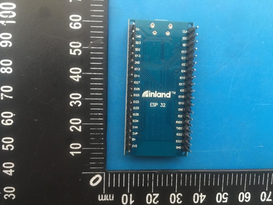
2ADMF-ESP32
May 25, 2020ESP32 Core Board (Black and Eco-friendly)
Equipment Class
DTS - Digital Transmission System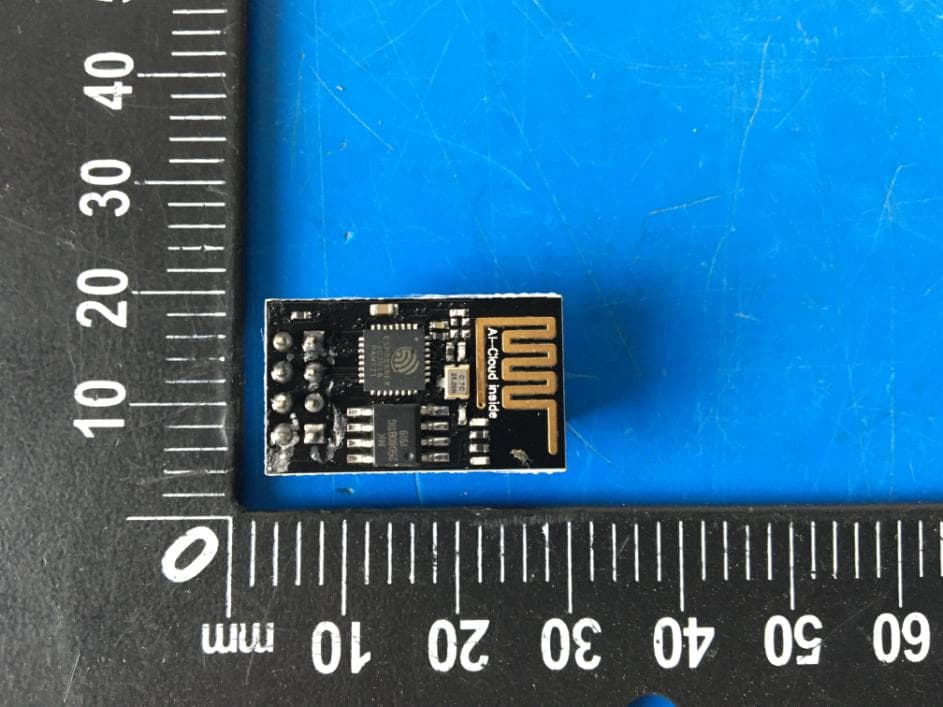
2ADMF-ESP8266
May 06, 2020ESP 8266 WIFI Module Kit
Equipment Class
DTS - Digital Transmission System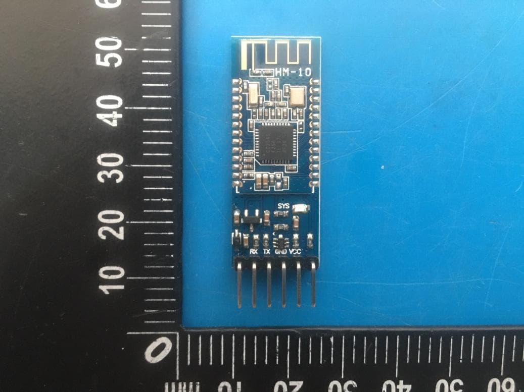
2ADMFHM-10
Apr 15, 2020HM-10 Bluetooth-4.0 V3 Compatible with HC-06 Pins
Equipment Class
DTS - Digital Transmission System
2ADMF-HC06
Nov 28, 2014bluetooth module
Equipment Class
DSS - Part 15 Spread Spectrum Transmitter