2ADPEDA011Dimming Switch Mini module
TRONICO TECHNOLOGY COMPANY LIMITED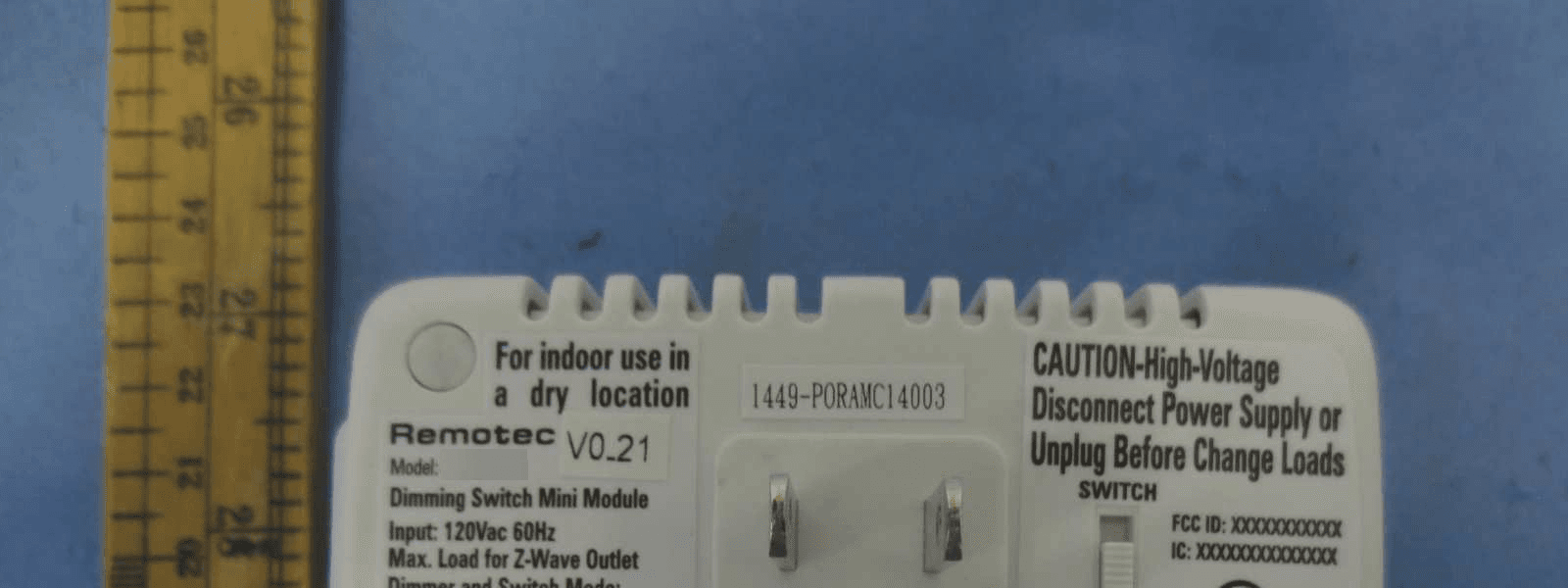
Click to zoom
Application Details
- Equipment Class
- DXT - Part 15 Low Power Transceiver, Rx Verified
- Date of Grant
- Feb 15, 2015
- Application Purpose
- Original Equipment
- Date of Application
- Feb 15, 2015
- Equipment Note
- Dimming Switch Mini module
- Frequency Range
- 908.42000000 - 908.42000000
- Country
- Hong Kong
Documents & Files
Document Text
Text extracted from the exhibit documents filed with the FCC. Open a document above to read the original.
Users Manual
Wireless Lighting Control ZDS-200NA Dimming Switch Module (Dual mode) USER MANUAL Introduction: Thank you for choosing the ZDS-200 (Dimming Switch Mini Module) Z-Wave control product! ZDS-200 enabled product allows users to remotely control lighting, home appliance, and make home control easy with low installation and maintenance costs. You may begin with a few Z-Wave enabled devices as well as some of our products to build up a complete home automation system. The ZDS-200 is a Z-Wave enabled device and is fully compatible with any Z- Wave enabled network. It can be configured as either a "DIMMER" or a "SWITCH" device. It allows remote Dimming or ON/OFF control of specified lamps. Each module is designed to act as a repeater, which will re-transmit a radio frequency (RF) signal by routing the signal around obstacles and radio dead spots to ensure that the signal is received at its intended destination. Glossary Device / Light / Node Devices, lights and nodes are all terms to describe an individual Z- Wave device. These terms are all interchangeable when setting up your Z-Wave network. A collection of Z-Wave devices are controlled by primary and secondary controllers operating on the same system. A Z-Wave network has its own unique ID code so that controllers not in the network cannot control the system. Add a Z-Wave device to the network. Delete a Z-Wave device from the network. Network Wide Inclusion (NWI) enables both end-user friendly, Plug and Play like Z-Wave network installation as well as professional installation scenario where the inclusion process in terms of time will be reduced significantly. NWI is a feature supported by a new frame type named Explorer which enables the Z-Wave protocol to implement Adaptive Source Routing. Association is used to organize nodes into different groups allowing the device to identify the nodes with a group identifier. These groups can also be copied to other devices. A scene is a collection of Z-Wave devices configured to turn to a specific level, setting, mode, or perform an operation. Scenes are usually activated by a controller, timed event, or a specific condition. Exclusion Inclusion 1 Z-Wave Network Network Wide Inclusion (NWI) 400x224mm fold to 80 x112mm Association Scene Key Features: -Supports Dual mode (DIMMER and SWITCH) -Remote ON/OFF/DIM control via the Z-Wave controller -Manual ON/OFF/DIM control with the front panel push button -Support Scene control -Support Association Group and Auto Report switch status -Supports Network Wide Inclusion (NWI) and Explore Frames -High output power in DIMMER and SWITCH mode -Over temperature protection -Grounded 3-wire power connection for safety -Does not block lower outlet when plugged into upper outlet of a duplex wall receptacle Product Overview: A Status LED BON/OFF/DIMMER/PROG Push button CZ-Wave controlled outlet DAC plug ESelective switch (SWITCH or DIMMER Mode) A B C D E Installation and The incandescent light plugged into the Z-Wave controlled outlet on this module must not exceed 330 watts. DO NOT connect fluorescent light. Plugging a non-resistive load such as fluorescent light or a device with a motor into the Z-Wave controlled outlet may result in damage to the ZDS-200 Dimming Switch Module and will void the warranty. ZDS-200 will not block the lower outlet when plugged into upper outlet of a duplex wall receptacle. Possible configurations are illustrated below. Warning Basic Operation The connected device can be turned ON in two ways: 1.Manual control with the push button on the ZDS-200. 2.Z-Wave remote controller. Manual ON/OFF/DIM function 1.Switch to DIMMER mode. ZDS-200 can be configured as either a "DIMMER" or a "SWITCH" device, and it will detect the operation mode using the position of the slide switch when powering on. Warning: -SWITCH Mode is required for inductive and capacitive devices unsuitable for dimming, (e.g. fluorescent lamps, motors etc.). The dimming function will be disabled in this mode. -It could damage the ZDS-200 if connected to non-dimmable load and perform dimming function in DIMMER mode! Grounded AC outlet VS 2-pins AC power plug Grounded AC outlet VS 3-pins AC power plug Installed at upper AC outlet Installed at lower AC outlet BW8330 TM (Z-URC 550) Push button BW8380 (ZRC-100) D I M M E R 234 67895 2.Plug the lamp into the ZDS-200 Z-Wave outlet. 3.Plug the ZDS-200 into a wall AC outlet. 4. 5. 6. 7. Ensure that the loading is not exceeding 330 Watts Incandescent. Press the button to turn the light ON/OFF. (This button is a toggle switch - press the button once to turn the light ON if the device is OFF and vice- versa) Pressing and holding the button will control the brightness. Release the button when the desired brightness is attained. (This is also a toggle function - press and hold the button to increase the brightness. To decrease the brightness, press and hold the button again.) Unplug the ZDS-200 from wall AC outlet. Switch to SWITCH mode. S W I T C H 8. Warning: -SWITCH Mode is required for inductive and capacitive devices unsuitable for dimming, (e.g. fluorescent lamps, motors etc.). The dimming function will be disabled in this mode. -It could damage the ZDS-200 if connected to non-dimmable load and perform dimming function in DIMMER mode! Plug the lamp into the ZDS-200 Z-Wave outlet. Ensure that the loading does not exceed 330 Watts Incandescent or 500 Watts Resistive Load. 9.Plug the ZDS-200 into a wall AC outlet. 10.Press the button to turn the light ON/OFF. (This button is a toggle switch - press the button once to turn the light ON if the device is OFF and vice- versa) Z-Wave setup and operations ZDS-200 can be configured as either a "DIMMER" or a "SWITCH" device, and it will detect the operation mode using the position of the slide switch when powering on. The ZDS-200 will stay in the selected operation mode after inclusion process, and it will not respond to the slide switch selection after removing and re-adding power. If the user needs …
Text truncated - open the document above for the full version.
External Photos
External Photos
ID Label/Location Info
This device complies with Part 15 of the FCC Rules. Operation is subject to the following two conditions: (1) this device may not cause harmful interference, and (2) this device must accept any interference received, including interference that may cause undesired operation. M a x . 3 3 0 W I n c a n d e s c e n t Item Description: Cabinet Bottom Attachment: Model: ZDS-200NA, ZDS-210NA, DA011, NND030, NND031 Remotec Technology Limited Prepared Tolerance for printing position: +/- 0.3mm Material: ABS Revision Checked Date Area Description Date C.H.CHANA Release for marketing Sample request quantity: Sample request date: Printing color: Black ITEM SPECIFICATION P/N: TBC 1/26/15 Plastic color: White Remotec MODEL: Released for PRELIMINARY INFORMATION QUOTATION ONLY MOCK UP ONLY HARD/SOFT TOOLING TOOL MODIFICATION TECHNICAL MANUAL MANUFACTORY PRINTING MARKETING Prepared by C.H.CHAN Date: 1/26/15 Approved by Date: 2mm 40.1mm Model: ZDS-200NA Dimming Switch Mini Module For indoor use in a dry location Input: 120Vac 60Hz Max. Load for Z-Wave Outlet FCC ID: 2ADPEDA011 IC: 12524A-DA011 Made in China SWITCH DIMMER Dimmer and Switch Mode: 330W(2.75A) Incandescent Load Switch Mode: 500W(4.16A) Resistive Load Reference Label (No need print the dot line) XXXX XXXXXXX 100 53.8 CAUTION-High-Voltage Disconnect Power Supply or Unplug Before Change Loads and Appliances 2mm 15.5mm 3.2mm 13.1mm 48mm Model: ZDS-200NA Dimming Switch Mini Module For indoor use in a dry location Input: 120Vac 60Hz Max. Load for Z-Wave Outlet FCC ID: 2ADPEDA011 IC: 12524A-DA011 Made in China SWITCH DIMMER Dimmer and Switch Mode: 330W(2.75A) Incandescent Load Switch Mode: 500W(4.16A) Resistive Load XXXX XXXXXXX CAUTION-High-Voltage Disconnect Power Supply or Unplug Before Change Loads and Appliances Model: ZDS-210NA Dimming Switch Mini Module For indoor use in a dry location Input: 120Vac 60Hz Max. Load for Z-Wave Outlet FCC ID: 2ADPEDA011 IC: 12524A-DA011 Made in China SWITCH DIMMER Dimmer and Switch Mode: 330W(2.75A) Incandescent Load Switch Mode: 500W(4.16A) Resistive Load XXXX XXXXXXX CAUTION-High-Voltage Disconnect Power Supply or Unplug Before Change Loads and Appliances Model: DA011 Dimming Switch Mini Module For indoor use in a dry location Input: 120Vac 60Hz Max. Load for Z-Wave Outlet FCC ID: 2ADPEDA011 IC: 12524A-DA011 Made in China SWITCH DIMMER Dimmer and Switch Mode: 330W(2.75A) Incandescent Load Switch Mode: 500W(4.16A) Resistive Load XXXX XXXXXXX CAUTION-High-Voltage Disconnect Power Supply or Unplug Before Change Loads and Appliances Model: NND030 Dimming Switch Mini Module For indoor use in a dry location Input: 120Vac 60Hz Max. Load for Z-Wave Outlet FCC ID: 2ADPEDA011 IC: 12524A-DA011 Made in China SWITCH DIMMER Dimmer and Switch Mode: 330W(2.75A) Incandescent Load Switch Mode: 500W(4.16A) Resistive Load XXXX XXXXXXX CAUTION-High-Voltage Disconnect Power Supply or Unplug Before Change Loads and Appliances Model: NND031 Dimming Switch Mini Module For indoor use in a dry location Input: 120Vac 60Hz Max. Load for Z-Wave Outlet FCC ID: 2ADPEDA011 IC: 12524A-DA011 Made in China SWITCH DIMMER Dimmer and Switch Mode: 330W(2.75A) Incandescent Load Switch Mode: 500W(4.16A) Resistive Load XXXX XXXXXXX CAUTION-High-Voltage Disconnect Power Supply or Unplug Before Change Loads and Appliances Model: 9613+06500-1UOP Dimming Switch Mini Module For indoor use in a dry location Input: 120Vac 60Hz Max. Load for Z-Wave Outlet FCC ID: 2ADPEDA011 IC: 12524A-DA011 Made in China SWITCH DIMMER Dimmer and Switch Mode: 330W(2.75A) Incandescent Load Switch Mode: 500W(4.16A) Resistive Load XXXX XXXXXXX CAUTION-High-Voltage Disconnect Power Supply or Unplug Before Change Loads and Appliances Model: 9613+06500-2UOP Dimming Switch Mini Module For indoor use in a dry location Input: 120Vac 60Hz Max. Load for Z-Wave Outlet FCC ID: 2ADPEDA011 IC: 12524A-DA011 Made in China SWITCH DIMMER Dimmer and Switch Mode: 330W(2.75A) Incandescent Load Switch Mode: 500W(4.16A) Resistive Load XXXX XXXXXXX CAUTION-High-Voltage Disconnect Power Supply or Unplug Before Change Loads and Appliances Model: 9613+06500-3UOP Dimming Switch Mini Module For indoor use in a dry location Input: 120Vac 60Hz Max. Load for Z-Wave Outlet FCC ID: 2ADPEDA011 IC: 12524A-DA011 Made in China SWITCH DIMMER Dimmer and Switch Mode: 330W(2.75A) Incandescent Load Switch Mode: 500W(4.16A) Resistive Load XXXX XXXXXXX CAUTION-High-Voltage Disconnect Power Supply or Unplug Before Change Loads and Appliances F-BW8130US-0001 Dimming Switch Mini Module For indoor use in a dry location Input: 120Vac 60Hz Max. Load for Z-Wave Outlet FCC ID: 2ADPEDA011 IC: 12524A-DA011 Made in China SWITCH DIMMER Dimmer and Switch Mode: 330W(2.75A) Incandescent Load Switch Mode: 500W(4.16A) Resistive Load XXXX XXXXXXX CAUTION-High-Voltage Disconnect Power Supply or Unplug Before Change Loads and Appliances F-BW8131US-0001 Dimming Switch Mini Module For indoor use in a dry location Input: 120Vac 60Hz Max. Load for Z-Wave Outlet FCC ID: 2ADPEDA011 IC: 12524A-DA011 Made in China SWITCH DIMMER Dimmer and Switch Mode: 330W(2.75A) Incandescent Load Switch Mode: 500W(4.16A) Resistive Load XXXX XXXXXXX CAUTION-High-Voltage Disconnect Power Supply or Unplug Before Change Loads and Appliances Model: Model:
Internal Photos
Internal Photos
RF Exposure Info
INTERTEK TESTING SERVICES RF Exposure The Equipment Under Test (EUT) is a Dimming Switch Mini module transceiver connected directly to AC 120V/60Hz main line. It is designed to act as a repeater, which will re-transmit the 908.42MHz RF signal (when receive a command signal from the remote controller) to ensure that the signal is received. It also has manual function. For more detail information pls. refer to the user manual. Modulation Type: FSK. Antenn a Type: Integral antenna. Antenna Gain: 0dBi The nominal radiated output power (e.r.p) specified: -12.15dBm (+/- 3dB) The nominal conducted output power specified: -10dBm (+/- 3dB) Accor ding to the KDB 447498: The maximun peak radiated emission for the EUT is 87.9dBμV/m at 3m The EIRP = [(FS*D) ^2 / 30] mW = -7.33dBm The ERP = EIRP - 2.15dBi = -9.48dBm which is within the production variation. The maximun conducted output power specified is -7dBm = 0.2mW T he source- based time-averaging conducted output power = 0.2 * Duty Cycle mW (where Duty Cycle ≤ 100%) ≤ 0.2 mW The SAR Exclusion Threshold Level: = 3.0 * (min. test separation distance, mm) / sqrt(freq. in MHz) = 3.0 * 5 / sqrt (0.9 08) mW = 15.7 mW Si nce the source-based time-averaging conducted output power is well below the SAR low threshold level, so the EUT is considered to comply with SAR requirement without testing. FCC ID: 2ADPEDA011
Test Report
• The test results reported in this test report shall refer only to the sample actually tested and shall not refer or be deemed to refer to bulk from which such a sample may be said to have been obtained. • This report is for the exclusive use of Intertek's Client and is provided pursuant to the agreement between Intertek and its Client. Intertek's responsibility and liability are limited to the terms and conditions of the agreement. Intertek assumes no liability to any party, other than to the Client in accordance with the agreement, for any loss, expense or damage occasioned by the use of this report. Only the Client is authorized to copy or distribute this report. Any use of the Intertek name or one of its marks for the sale or advertisement of the tested material, product or service must first be approved in writing by Intertek. The observations and test results referenced from this report are relevant only to the sample tested. This report by itself does not imply that the material, product, or service is or has ever been under an Intertek certification program. • For Terms And Conditions of the services, it can be provided upon request. • The evaluation data of the report will be kept for 3 years from the date of issuance. TRF No.: FCC 15C_TX_ Intertek Testing Services Shenzhen Ltd. Kejiyuan Branch 6F, D Block, Huahan Building, Langshan Road, Nanshan District, Shenzhen, P. R. China Tel: (86 755) 8601 6288 Fax: (86 755) 8601 6751 Website: www.china.intertek-etlsemko.com TRONICO TECHNOLOGY COMPANY LIMITED Application For Certification FCC ID: 2ADPEDA011 Dimming Switch Mini module Model: DA011 Additional Model: 9613+06500-1UOP, NND030, 9613+06500- 2UOP, NND031, 9613+06500-3UOP, F-BW8130US-0001, ZDS-200NA, F- BW8131US-0001, ZDS-210NA Report No.: 150120028SZN-001 We hereby certify that the sample of the above item is considered to comply with the requirements of FCC Part 15, Subpart C for Intentional Radiator, mention 47 CFR [10-1-13] Prepared and Checked by: Approved by: Sign on file Vincent Chen Engineer Andy Yan Senior Project Engineer Date: January 28, 2015 INTERTEK TESTING SERVICES TRF No.: FCC 15C_TXb FCC ID: 2ADPEDA011 i LIST OF EXHIBITS INTRODUCTION EXHIBIT 1: General Description EXHIBIT 2: System Test Configuration EXHIBIT 3: Emission Results EXHIBIT 4: Equipment Photographs EXHIBIT 5: Product Labelling EXHIBIT 6: Technical Specifications EXHIBIT 7: Instruction Manual EXHIBIT 8: Miscellaneous Information EXHIBIT 9: Test Equipment List INTERTEK TESTING SERVICES TRF No.: FCC 15C_TXb FCC ID: 2ADPEDA011 ii MEASUREMENT/TECHNICAL REPORT TRONICO TECHNOLOGY COMPANY LIMITED - Model: DA011 Additional Model: 9613+06500-1UOP, NND030, 9613+06500-2UOP, NND031, 9613+06500-3UOP, F-BW8130US-0001, ZDS-200NA, F-BW8131US-0001, ZDS-210NA FCC ID: 2ADPEDA011 January 28, 2015 This report concerns (check one:) Original Grant X Class II Change Equipment Type: DXT - Part 15 Low Power Transceiver, RX Verified Deferred grant requested per 47 CFR 0.457(d)(1)(ii)? Yes No X If yes, defer until: date Company Name agrees to notify the Commission by: date of the intended date of announcement of the product so that the grant can be issued on that date. Transition Rules Request per 15.37? Yes No X If no, assumed Part 15, Subpart C for intentional radiator − the new 47 CFR [10-1-13 Edition] provision. Report prepared by: Vincent Chen Intertek Testing Services Shenzhen Ltd. Kejiyuan Branch 6F, Block D, Huahan Building, Langshan Road, Nanshan District, Shenzhen, P. R. China Phone: (86 755) 8601 0684 Fax: (86 755) 8601 6751 INTERTEK TESTING SERVICES TRF No.: FCC 15C_TXb FCC ID: 2ADPEDA011 iii Table of Contents 1.0 General Description ............................................................................................ 2 1.1 Product Description ............................................................................................ 2 1.2 Related Submittal(s) Grants ............................................................................... 2 1.3 Test Methodology ............................................................................................... 3 1.4 Test Facility ........................................................................................................ 3 2.0 System Test Configuration ................................................................................. 5 2.1 Justification ........................................................................................................ 5 2.2 Special Accessories ........................................................................................... 5 2.3 Equipment Modification ...................................................................................... 5 2.4 Measurement Uncertainty .................................................................................. 5 2.5 Support Equipment List and Description ............................................................. 6 3.0 Emission Results ................................................................................................ 8 3.1Radiated Test Results............................................................................ 9 3.1.1 Field Strength Calculation ................................................................................ 9 3.1.2 Radiated Emission Configuration Photograph ................................................ 10 3.1.3 Radiated Emissions ....................................................................................... 10 3.2 Conducted Emission at Mains Terminal................................................... 12 3.2.1 Conducted Emissions Configuration Photograph......................................12 3.2.2 Conducted Emissions........................................................................12 4.0 Equipment Photographs ................................................................................... 16 5.0 Product Labelling .......................................................................................…
Text truncated - open the document above for the full version.
Test Setup Photos
Radiated Photos
Test Setup Photos
Conducted Photos
Contact Information
Applicant
Alex Chan
Technical Contact
Intertek Testing Services Shenzhen Ltd. Kejiyuan BShawn Xing
[email protected](86-755) 8614 0603
6F, D Block, Huahan Building, Langshan Road · Shenzhen · China
Non-Technical Contact
Intertek Testing Services Shenzhen Ltd. Kejiyuan BShawn Xing
[email protected](86-755) 8614 0603
Test Firm
Intertek Testing Services Shenzhen Ltd.Shawn Xing
Technical Specifications
| # | Rule Parts | Frequency Range | Power Output |
|---|---|---|---|
| 1 | 15C | 908.42 MHz - 908.42 MHz | - |
Other Applications from TRONICO TECHNOLOGY COMPANY LIMITED
2ADPENNC014
Feb 02, 2015Direct Plug-in Z-Wave Repeater
Equipment Class
DXT - Part 15 Low Power Transceiver, Rx Verified