Text extracted from the exhibit documents filed with the FCC. Open a document above to read the original.
Seite 1/9 USER’S MANUAL Fidbox V.6-1 FW: V 1.2 Seite 2/9 CONTENTS 1 PRODUCT DESCRIPTION 4 1.1 General..................................................................................... 4 1.2 Technical data.................................................................. 5 1.3 Installation Instructions.................................................................. 6 1.4 Certificates .................................................................................... 8 1.4.1 EMC ........................................................................................... 8 1.4.2 EMI ............................................................................................. 8 1.4.3 FCC ............................................................................................ 8 1.4.4 IC ................................................................................................ 9 Seite 3/9 VERSION INDEX Version Date Author Description 1.0.0 01.05.2013 SM Initial document 1.0.1 06.05.2013 SM Additional FCC Information Seite 4/9 1 Product description 1.1 General The fidbox® is a monitor for temperature (°C) and relative humidity (%) as well as a data log for long-term data recording all in one, which is concealed in the hardwood flooring itself. The data stored therein can be read at any time by wireless transmission and allows the determination of the degree of moisture in the screed and in the hardwood flooring by vertical measurements. This information is not only pertaining to the indoor environment, but is especially important in the event of damage as it provides understandable facts. For example, if damage occurs to the floor due to excessive floor temperature in the hardwood or through increasing or decreasing of moisture, often a lengthy fundamental research as to cause is needed and this might result in unjust blame. The fidbox® puts a stop to that and provides unadulteratable clarity as to the question of guilt; prompt – candid - definite! The fidbox® brings measurable benefits to the hardwood installer, designers, owners, occupants or builders. The results of the measurements can quickly clarify damage claims and thus speed up the process of clarification and solution. The fidbox® is a product that is directed at resolving a genuine problem and it offers a lot of extra security on top. The relevance of this subject itself is apparent, as many damage claims can eventually endanger the pure existence of many hardwood installation companies. The fidbox® provides unadulteratable results that are recognized by hardwood flooring inspectors and therefore an important element in the preparation of a court case. Seite 5/9 1.2 Technical data Carrier 2.4 GHz ISM- Frequency Band Protocol proprietary Number of channels 1 Output power max. -20 dBm Power supply voltage 3 V DC Lithium Battery Current consumption avg. 15 mA – 5 μA (power down Ambient temperature 0°C to +55°C Weight 30 g Dimensions (W x H x D) 95.5 mm x 52.5 mm x 7 mm Humidity Accuracy: up to +/- 2% rH Resolution: 0,04% rH Repeatability: up to +/- 0,1% rH Temperature Accuracy: up to +/- 0,3°C bei +25°C Resolution: 0,01°C Repeatability: up to +/- 0,1°C Seite 6/9 1.3. Installation Instructions Congratulations, you have decided to install the fidbox ® . This was a good decision for your future security and the health of your clients. When the fidbox® that you ordered leaves our humidity chamber, we check it for complete functionality and provide you with our warranty. Please pay attention to the following recommendations and help ensure the flawless functioning of the fidbox®. Choose the optimal location for the fidbox® together with the builder or architect before installation. The fidbox® should be integrated into rooms with the highest room climate variability, for example, in the middle of the room or above areas of underfloor heating. A minimum of one fidbox® should be planned for each room with a size greater than 30 m² of floor space at a distribution of one per 50 m² of total wood floor area. In multi-story buildings and/or rooms with multiple heating circuits there should be at least one fidbox® per floor or heating circuit. We will gladly provide support during the planning stage. See our pamphlet regarding “Where to place the fidbox®”, which is available on our website. Please Observe: (reading errors may occur by non-observance) no furniture should be placed over or on the position of the fidbox® do not lay textile rugs over the position of the fidbox® avoid strong magnetic fields on or above the fidbox® Warning! Store the fidbox®, dry and frost-proof at room temperature (+17°C to + 23°C) Safeguard the fidbox® in the supplied storage box until ready for use. Never subject the unprotected fidbox® to direct sunlight or submerge in water. Do not crack or bend. Never drill or saw through the fidbox®. Do not store the fidbox® near magnetic fields. In case of loss of battery power the stored data remains intact for many years after power loss and can be recovered. In this case contact floorprotector. Visit our website at www.floorprotector.at for further information.You will find among other things the technical data sheets and the translation of this installation instruction in other languages an information about our new fidbox® APP. Seite 7/9 Step by Step 1st step The fidbox® should be installed into the wood floor directly under the top layer. Attention: please note that at least 3 mm of the top layer must remain. Otherwise a crack in the hardwood element can occur. It is necessary to mill out the necessary recess in the wood floor in the required dimensions (l x w x d) of the fidbox® 9.5 x 5.3 x 0.8cm (in addition to a min. 8 mm the hardwood panel edge) with the aid of a template. This can be accomplished professionally using a router or with the use of suitable tools. 2nd step During the wood floor installation the cover of the adhesive strips which is applied to one side of the fidbox® is peeled…
Text truncated - open the document above for the full version.
THIS MUST BE SIGNED BY THE APPLICANT/AGENT AND SHOULD BE PLACED ON APPROPRIATE LETTERHEAD Request for Confidentiality Date: 2015-30-01 Subject: Confidentiality Request for: FCC ID:2ADQTV6 IC ID: 12568A-V6 Pursuant to FCC 47 CRF 0.457(d) and 0.459 and IC RSP-100, Section 6.4, the applicant requests that a part of the subject FCC application be held confidential. Type of Confidentiality Requested Exhibit Short Term Permanent Block Diagrams Short Term External Photos Short Term Permanent* 1 Internal Photos Short Term Permanent Operation Description/Theory of Operation Short Term Permanent Parts List & Placement/BOM Short Term Permanent Tune-Up Procedure Short Term Permanent Schematics Short Term Test Setup Photos Short Term Permanent* User’s Manual *Note: ______(Insert Explanation as Necessary)______ FP Floor Protector GmbH has spent substantial effort in developing this product and it is one of the first of its kind in industry. Having the subject information easily available to "competition" would negate the advantage they have achieved by developing this product. Not protecting the details of the design will result in financial hardship. Permanent Confidentiality: The applicant requests the exhibits listed above as permanently confidential be permanently withheld from public review due to materials that contain trade secrets and proprietary information not customarily released to the public. Short-Term Confidentiality: The applicant requests the exhibits selected above as short term confidential be withheld from public view for a period of ___(specify number of days not to exceed 180) 2 ___ days from the date of the Grant of Equipment Authorization and prior to marketing. This is to avoid premature release of sensitive information prior to marketing or release of the product to the public. Applicant is also aware that they are responsible to notify ACB in the event information regarding the product or the product is made available to the public. ACB will then release the documents listed above for public disclosure pursuant to FCC Public Notice DA 04-1705. NOTE for Industry Canada Applications: The applicant understands that until such time that IC distinguishes between Short Term and Permanent Confidentiality, either type of marked exhibit above will simply be marked Confidential when submitted to IC. Sincerely, Thomas Ring By: Manager Certification ________________________ (Signature/Title 3 ) (Print name) 1 - The asterisked items (*) require further justification before permanent confidentiality will be allowed. These also currently require review by the FCC under their Permit-But-Ask policy before the grant is issued and can delay completion of an application. Further justification should be added to the note above. One such example for a potted device would be: “The EUT is FULLY potted using a non-removable epoxy based material. Removal of potting material causes irreparable damage to internal circuitry. See photographs exhibits that outline the device before and after potting.” 2 - Please refer to http://acbcert.com/documents/misc-docs/Memo-Short-Term-Vs-Standard-Confidentiality.pdf for complete details. 3 - Must be signed by applicant contact given for applicant on the FCC site, or by the authorized agent if an appropriate authorized agent letter has been provided. Letters should be placed on appropriate letterhead.
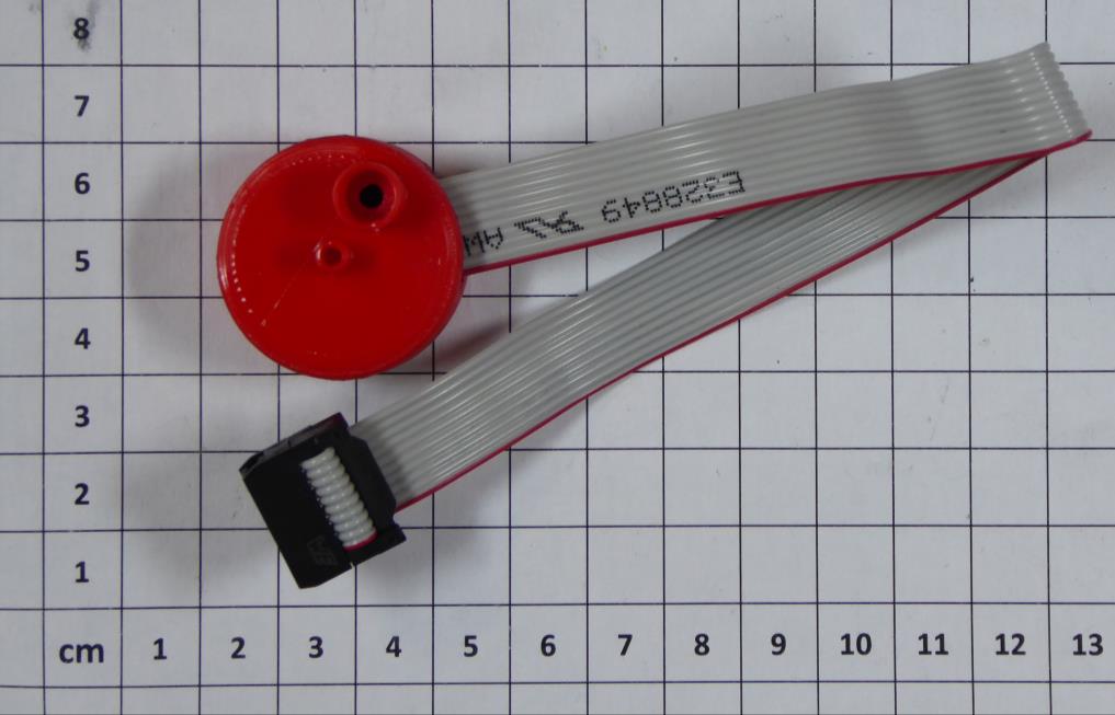
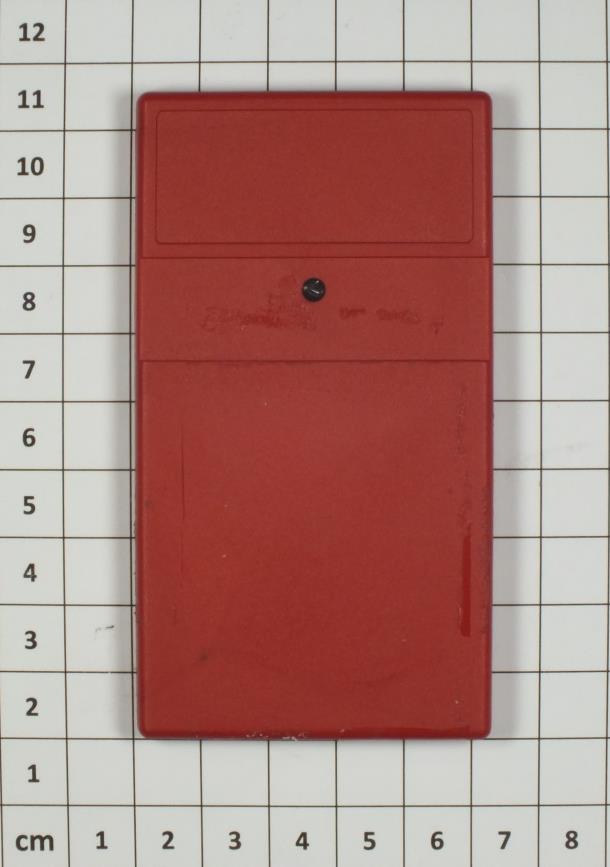
CSA Group Bayern GmbH File No. T38545-00-xxTK, page 3 of 5 Ohmstrasse 2-4 94342 STRASSKIRCHEN GERMANY Tel.: +49(0)9424-94810 Fax: +49(0)9424-9481440 Rev. No. 3.0 2014-01-30 1 P h o t o d o c u m e n t a t i o n o f t h e E U T 1.1 External views: Top view Bottom view
FCC LABEL - FIDBOX V6 Fidbox Label Label placed on product
CSA Group Bayern GmbH File No. T38545-00-xxTK, page 4 of 5 Ohmstrasse 2-4 94342 STRASSKIRCHEN GERMANY Tel.: +49(0)9424-94810 Fax: +49(0)9424-9481440 Rev. No. 3.0 2014-01-30 1.2 Internal views Opened housing, bottom side PCB bottom view PCB top view CSA Group Bayern GmbH File No. T38545-00-xxTK, page 5 of 5 Ohmstrasse 2-4 94342 STRASSKIRCHEN GERMANY Tel.: +49(0)9424-94810 Fax: +49(0)9424-9481440 Rev. No. 3.0 2014-01-30 1.3 Antenna structure: RF section and antenna application
FCC ID: 2ADQTV6 IC: 12568A-V6 CSA Group Bayern GmbH File No. T38545-00-02TK, page 1 of 31 Ohmstrasse 1-4 94342 STRASSKIRCHEN GERMANY Tel.:+49(0)9424-94810 Fax: ++49(0)9424-9481440 Rev. No. 3.0, 2014-12-31 EMI − T E S T R E P O R T - FCC Part 15.247, RSS210 - Test Report No. : T38545-00-02TK 20. January 2015 ______________________________________________________________________________________________ Date of issue Type / Model Name : Fidbox V6 Product Description : Bluetooth module, low energy 4.0 Applicant : fp floor protector GmbH Address : Außermanzing 28 3033 ALTLENGBACH, AUSTRIA Manufacturer : fp floor protector GmbH Address : Außermanzing 28 3033 ALTLENGBACH, AUSTRIA Licence holder : fp floor protector GmbH Address : Außermanzing 28 3033 ALTLENGBACH, AUSTRIA Test Result according to the standards listed in clause 1 test standards: POSITIVE The test report merely corresponds to the test sample. It is not permitted to copy extracts of these test results without the written permission of the test laboratory. FCC ID: 2ADQTV6 IC: 12568A-V6 CSA Group Bayern GmbH File No. T38545-00-02TK, page 2 of 31 Ohmstrasse 1-4 94342 STRASSKIRCHEN GERMANY Tel.:+49(0)9424-94810 Fax: ++49(0)9424-9481440 Rev. No. 3.0, 2014-12-31 Contents 1 TEST STANDARDS 3 2 EQUIPMENT UNDER TEST 4 2.7 Antennas 5 3 TEST RESULT SUMMARY 7 3.1 Final assessment 7 4 TEST ENVIRONMENT 8 4.1 Address of the test laboratory 8 4.2 Environmental conditions 8 4.3 Statement of the measurement uncertainty 8 4.4 Measurement protocol for FCC and IC 9 5 TEST CONDITIONS AND RESULTS 10 5.1 AC power line conducted emissions 10 5.2 EBW and OBW 11 5.3 Maximum peak radiated output power 15 5.4 Power spectral density 17 5.5 Radiated emissions in restricted bands 20 5.6 Spurious emissions radiated 25 5.7 Antenna application 27 5.8 Maximum permissible exposure (MPE) 29 6 USED TEST EQUIPMENT AND ACCESSORIES 31 Attachment A as separte supplement FCC ID: 2ADQTV6 IC: 12568A-V6 CSA Group Bayern GmbH File No. T38545-00-02TK, page 3 of 31 Ohmstrasse 1-4 94342 STRASSKIRCHEN GERMANY Tel.:+49(0)9424-94810 Fax: ++49(0)9424-9481440 Rev. No. 3.0, 2014-12-31 1 TEST STANDARDS The tests were performed according to following standards: FCC Rules and Regulations Part 15, Subpart A - General (September, 2014) Part 15, Subpart A, Section 15.31 Measurement standards Part 15, Subpart A, Section 15.33 Frequency range of radiated measurements Part 15, Subpart A, Section 15.35 Measurement detector functions and bandwidths FCC Rules and Regulations Part 15, Subpart C - Intentional Radiators (September, 2014) Part 15, Subpart C, Section 15.203 Antenna requirement Part 15, Subpart C, Section 15.204 External radio frequency power amplifiers and antenna modifications Part 15, Subpart C, Section 15.205 Restricted bands of operation Part 15, Subpart C, Section 15.207 Conducted limits Part 15, Subpart C, Section 15.209 Radiated emission limits, general requirements Part 15, Subpart C, Section 15.247 Operation within the bands 902 - 928 MHz, 2400 - 2483.5 MHz and 5725 - 5850 MHz FCC Rules and Regulations Part 1, Subpart I - Procedures Implementing the National Environmental Policy Act of 1969 Part 1, Subpart I, Section 1.1310 Radiofrequency radiation exposure limits Part 1, Subpart 2, Section 2.1093 Radiofrequency radiation exposure evaluation: portable device OET Bulletin 65, 65A, 65B Edition 97-01, August 1997 – Evaluating Compliance with FCC Guidelines for Human Exposure to Radio Frequency Electromagnetic Fields. KDB 447498 D01 v05r02 Mobile and portable devices RF Exposure procedures and equipment authorisation policies, February 7, 2014. ANSI C63.4: 2014 Methods of Measurement of Radio-Noise Emissions from Low- Voltage Electrical and Electronic Equipment in the Range of 9 kHz to 40 GHz. ANSI C63.10: 2013 Testing Unlicensed Wireless Devices ANSI C95.1: 2005 IEEE Standard for Safety Levels with respect to Human Exposure to Radio Frequency Electromagnetic Fields, 3 kHz to 300 GHz CISPR 16-4-2: 2013 Uncertainty in EMC measurement KDB 558074 D01 v03r02 Guidance for performing compliance measurements on DTS operating under §15.247, June 5, 2014. FCC ID: 2ADQTV6 IC: 12568A-V6 CSA Group Bayern GmbH File No. T38545-00-02TK, page 4 of 31 Ohmstrasse 1-4 94342 STRASSKIRCHEN GERMANY Tel.:+49(0)9424-94810 Fax: ++49(0)9424-9481440 Rev. No. 3.0, 2014-12-31 2 EQUIPMENT UNDER TEST 2.1 Photo documentation of the EUT – Detailed photos see Attachment A 2.2 Equipment type Bluetooth Low Energy device for stationary use 2.3 Short description of the equipment under test (EUT) The EUT is a Bluetooth 4.0 Low Energy system. The EUT is compatible with the standard 802.15.1. It supports the 2.4 GHz frequency band. A single PCB antenna is used within the system. The modulation used by the EUT is GFSK with a data rate of 1000 kbits which means worst case for testing. The EUT has a special firmware that allows enabling a permanent advertising mode with three advertising channels. The output power is set to -23 dBm by firmware and cannot be changed during tests. The EUT has only one integrated antenna, no temporary connector and no external antenna can be connected. The EUT is run with a 3.0V Lithium cell battery. There are no external connectors. Number of tested samples: 1 MAC address: 20:CD:39:AE:7C:10 Serial number: N/A Firmware version: Test Firmware EUT configuration: (The CDF filled by the applicant can be viewed at the test laboratory.) 2.4 Variants of the EUT none 2.5 Operation frequency and channel plan The operating frequency is 2400 MHz to 2483.5 MHz. Note: the marked frequencies are determined for final testing. ChannelFrequencyChannelFrequency 372402182442 02404192444 12406202446 22408212448 32410222450 42412232452 52414242454 62416252456 72418262458 82420272460 92422282462 102424292464 382426302466 112428312468 122430322470 132432332472 142434342474 152436352476 162438362478 172440392480 FCC ID: 2ADQTV6 IC: 12568A-V6 CSA Group Bayern GmbH File No. T38545-00-02TK, page 5 of 31…
Text truncated - open the document above for the full version.
Ohmstrasse 1-4 · Strasskirchen · Germany
| # | Rule Parts | Frequency Range | Power Output |
|---|---|---|---|
| 1 | 15C | 2.40 GHz - 2.48 GHz | 5.10 µW |

Temperatue And Humidity Sensor With BLE Module
Equipment Class
DTS - Digital Transmission System