FCCID.CO- FCC ID Database
HomeCompaniesEquipment ClassesSearch

© 2026 FCC ID Database. All rights reserved.

AboutContactData sourced from FCC public records
  1. Home/
  2. Bosch Connected Devices and Solutions GmbH/
  3. 2ADSJTPS110

2ADSJTPS110Parking Lot Sensor

Bosch Connected Devices and Solutions GmbH
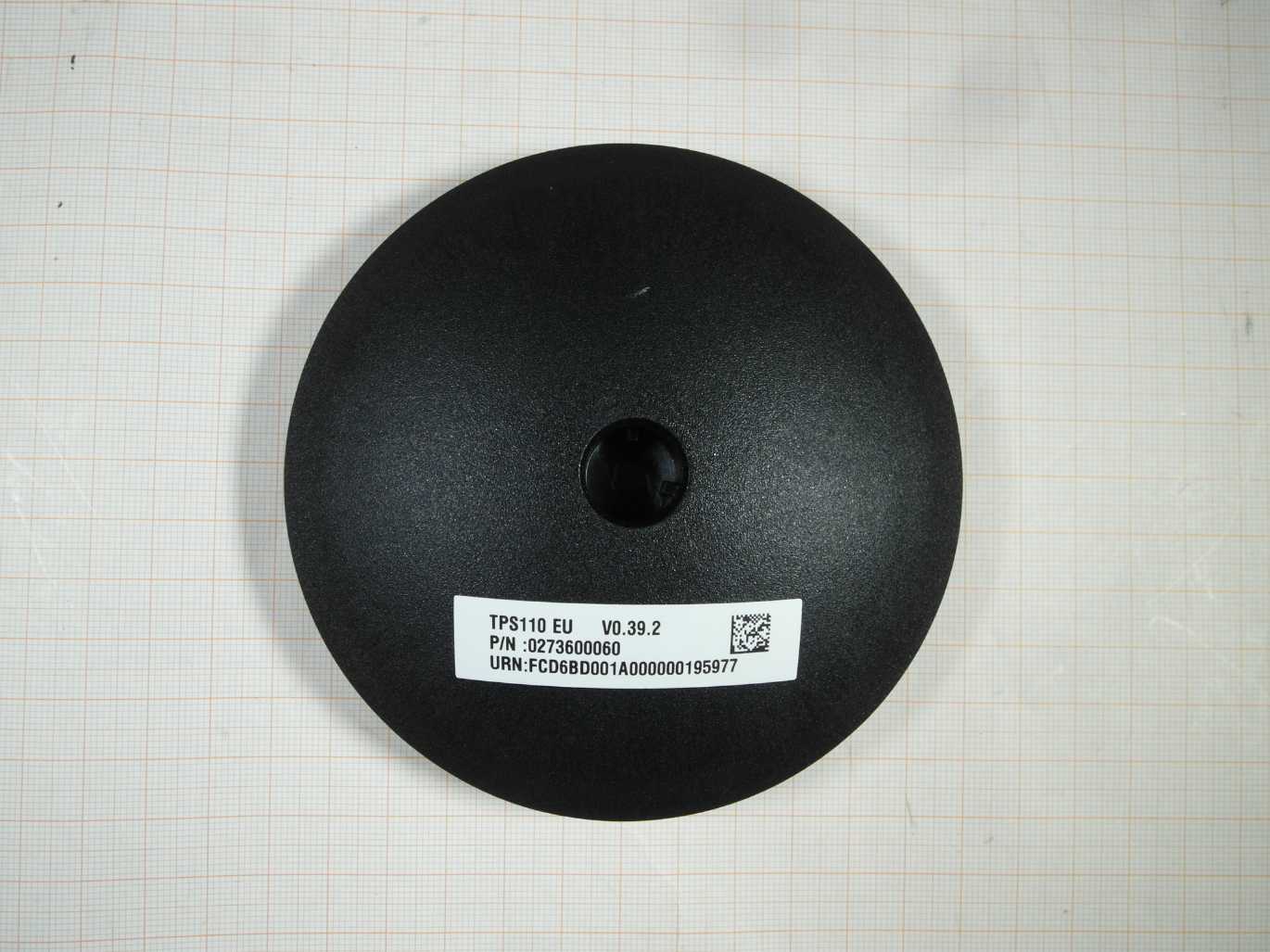
Parking Lot Sensor - FCC ID 2ADSJTPS110 - Bosch Connected Devices and Solutions GmbH
Click to zoom

Application Details

Equipment Class
DSS - Part 15 Spread Spectrum Transmitter
Date of Grant
May 18, 2021
Application Purpose
Original Equipment
Date of Application
May 18, 2021
Equipment Note
Parking Lot Sensor
Frequency Range
902.30000000 - 914.90000000
Company
Bosch Connected Devices and Solutions GmbH
Country
Germany

Documents & Files

Select a file to view

Users Manual

↗

Cover Letter(s)

↗
↗

External Photos

↗
↗

ID Label/Location Info

↗

Internal Photos

↗
↗

RF Exposure Info

↗

Test Report

↗

Test Setup Photos

↗

Document Text

Text extracted from the exhibit documents filed with the FCC. Open a document above to read the original.

Users Manual

© Bosch Connected Devices and Solutions GmbH 2021. All rights reserved, also regarding any disposal, exploitation, reproduction, editing, distribution, as well as in the event of application for industrial property rights. Parking Lot Sensor | PLS 1 | 18 User manual Parking Lot Sensor | PLS User manual 1.5 © Bosch Connected Devices and Solutions GmbH 2021. All rights reserved, also regarding any disposal, exploitation, reproduction, editing, distribution, as well as in the event of application for industrial property rights. Parking Lot Sensor | PLS 2 | 18 Table of contents 1 General description and intended use 3 2 Assembly and commissioning 3 2.1 Installation requirements ..................................................................................................................................... 3 2.2 Installing the sensor base ................................................................................................................................... 4 Required material for installing the parking lot sensor ....................................................................................... 4 Preparation of the parking space ....................................................................................................................... 5 Installation of the sensor base ........................................................................................................................... 6 2.3 Installing the sensor core .................................................................................................................................... 9 2.4 Replacing/removing the sensor ........................................................................................................................ 11 2.5 Setup and operation of the parking lot sensor in the backend .......................................................................... 11 3 Technical specifications 12 4 Legal information 13 4.1 Disposal note .................................................................................................................................................... 13 4.2 Manufacturer Information .................................................................................................................................. 13 4.3 European Union: EU Declaration of Conformity ............................................................................................... 13 4.4 Japan: Japanese Radio Law (電波法) Notice ................................................................................................... 13 4.5 India: Equipment Type Approval ....................................................................................................................... 13 4.6 Singapore: Equipment Registration .................................................................................................................. 14 4.7 Australia: Declaration of Conformity ................................................................................................................ 14 4.8 Hongkong: Declaration of Conformity ............................................................................................................... 14 4.9 Republic of South Africa: Equipment Type Approval......................................................................................... 14 4.10 Federal Communications Commission (FCC) Notice ....................................................................................... 14 4.11 ISED Canada (IC) Notice .................................................................................................................................. 15 4.12 Note for transport .............................................................................................................................................. 15 4.13 OSS note ........................................................................................................................................................... 16 © Bosch Connected Devices and Solutions GmbH 2021. All rights reserved, also regarding any disposal, exploitation, reproduction, editing, distribution, as well as in the event of application for industrial property rights. Parking Lot Sensor | PLS 3 | 18 1 General description and intended use The Parking Lot Sensor (PLS) with TPS110 sensor core is designed for detecting parked vehicles in parking lots. This user manual is valid for the PLS with TPS110 sensor core by BCDS. The Parking Lot Sensor with TPS110 sensor core is not designed for use in life-sustaining applications, safety-critical applications or applications for which a malfunction could lead to bodily harm, death or severe property damage. Only use the Parking Lot Sensor with components approved by BCDS. 2 Assembly and commissioning 2.1 Installation requirements Warning Read carefully and keep the user manual for future reference. The Product, as referenced in this manual, is the complete hardware package for the Parking Lot Sensor, including the Cap, Screw, Core and Base. Follow these instructions and all information. ⇒ The Customer must comply with all applicable laws and regulations for the installation and operation of the Product, and if necessary, obtain necessary approvals. The Customer must take appropriate measures to avoid injury of third parties, for example, by them tripping over the Product. Therefore, the Product should only be installed in a clearly designated parking space and should not, for instance, be installed on the sidewalk. Before installing the sensors, make sure that the necessary infrastructure is working properly - make sure the gateways are switched on, that a stable Internet connection has been established, and that there is a backend connection. The backend, as well as the associated management software, must be functional. Make sure that all of the required components (see Fig. 1 Parking Lot Sensor with TPS110 sensor core), as well as the tools, are ready. Figure…

Text truncated - open the document above for the full version.

Cover Letter(s)

CONFIDENTIALITY REQUEST for CertificationServiceinUSA FederalCommunicationCommission Equipment Authorization Division, ApplicationProcessing Branch 7435OaklandMills Road Columbia,MD 21048 29 April 2021 TO WHOM IT MAYCONCERN Pursuantto Paragraphs §0.457 and0.459ofthe Commission'sRules (47C.F.R.) and Section§552(b)(4)ofthe FreedomofInformationAct,werequestsconfidentiality forthe following products: FCCID Model name 2ADSJTPSIIO TPSIIO Forthe product statedabove, we request permanentconfidentiality forexhibitswhich contain Operational Description, Block Diagram, Schematics, PartsListsorTuneUp Information. Theaboveexhibitscontainour tradesecretsandproprietary informationthatcouldbeof benefittoourcompetitors. Ifyou haveany questions, pleasefeel freetocontactmeattheaddressshown below. Sincerely, / Y / i.V.L ')?- - (signed) Name:ChristianBrechtmann HeadofQuality Management Phone:+491704848530 Email: Christian.Brechtmannbosch-connectivity.com PeterSteinhauser Headof CommercialResponsibility +49(7121)35-0 Peter.Steinhauserde.bosch.com Company:BoschConnected DevicesandSolutionsGmbH Address:Ludwig - Erhard - Str.2 72760 Reutlingen I Germany

Cover Letter(s)

SHORT-TERMCONFIDENTIALITYREQUEST FederalCommunicationCommission EquipmentAuthorization Division, ApplicationProcessing Branch 7435OaldandMillsRoad Columbia, MD 21048 29April 2021 TOWHOMITMAY CONCERN Pursuant to Paragraphs §0.457 and 0.459 oftheCommission'sRules (47 C.F.R.) and Section §552(b)(4) oftheFreedomofInformation Act, we requests shortterm confidentiality forthe following product: FCC ID NumberProduct Title/Model 2ADSJTPS11O TPS110 Forthe productstated above, we request thatthe following informationbeheld confidential: 1.ExternalandInternal Photographs 2.Test SetupPhotos 3.UserManual We request this confidentiality onthebasisof ensuring that businesssensitive information remainsconfidentialuntiltheactual marketing of ournew device, whichisplannedfor 01 June 2021. If youhave any questions,pleasefeel free tocontactmeattheaddressshownbelow. Sincerely, (signed) Name: ChristianBrechtmann Headof QualityManagement Phone: +49 1704848530 Email: [email protected] PeterSteinhauser Headof Commercial Responsibility +49(7121)35-0 [email protected] Company:BoschConnectedDevicesandSolutionsGmbH Address:Ludwig - Erhard - Str.2 I 72760 Reutlingen I Germany

External Photos

Annex A 1-9831/20-05-01_AnnexA External photos of the Equipment Under Test This addendum is electronically signed and valid without handwritten signature. For verification of the electronic signatures, the public keys can be requested at the testing laboratory. Document authorized: Andreas Kurzkurt Testing Manager Radio Communications & EMC CTC advanced GmbHUntertuerkheimer Str. 6-10 66117 Saarbruecken / Germany Phone: +49 681 5 98 - 0 Fax: +49 681 5 98 - 9075 web: ctcadvanced.com e-mail: [email protected] Photos Photo 1 Photo 2 2021-04-30Document No. 1-9831/20-05-01_AnnexA2/4 Photo 3 2021-04-30Document No. 1-9831/20-05-01_AnnexA3/4 Document history VersionApplied changesDate of release initial release2021-04-30 - END OF DOCUMENT - 2021-04-30Document No. 1-9831/20-05-01_AnnexA4/4

Internal Photos

Annex B 1-9831/20-05-01_AnnexB Internal photos of the Equipment Under Test This addendum is electronically signed and valid without handwritten signature. For verification of the electronic signatures, the public keys can be requested at the testing laboratory. Document authorized: Andreas Kurzkurt Testing Manager Radio Communications & EMC CTC advanced GmbHUntertuerkheimer Str. 6-10 66117 Saarbruecken / Germany Phone: +49 681 5 98 - 0 Fax: +49 681 5 98 - 9075 web: ctcadvanced.com e-mail: [email protected] Photos Photo 1 Photo 2 PCB+Battery 2021-04-30Document No. 1-9831/20-05-01_AnnexB2/7 Photo 3 PCB Top Photo 4 PCB Bottom 2021-04-30Document No. 1-9831/20-05-01_AnnexB3/7 Photo 5 Battery Photo 6 Battery 2021-04-30Document No. 1-9831/20-05-01_AnnexB4/7 Photo 7 DUT Programming Board (JIG) Bottom Photo 8 DUT Programming Board (JIG) Top 2021-04-30Document No. 1-9831/20-05-01_AnnexB5/7 Photo 9 DUT Programming Board (JIG) + DUT PCB 2021-04-30Document No. 1-9831/20-05-01_AnnexB6/7 Document history VersionApplied changesDate of release initial release2021-04-30 - END OF DOCUMENT - 2021-04-30Document No. 1-9831/20-05-01_AnnexB7/7

RF Exposure Info

© CTC advanced GmbH Page 1 of 3 BNetzA - CAB - 02/21 - 102 Maximum Permissible Exposure (MPE) & Exposure evaluation Report identification number: 1-9831/20-05-05 MPE (FCC_ISED) Certification numbers and labeling requirements FCC ID 2ADSJTPS110 ISED number 12595A-TPS110 HVIN (Hardware Version Identification Number) TPS110 PMN (Product Marketing Name) PLS FVIN (Firmware Version Identification Number) -/- HMN (Host Marketing Name) -/- This test report is electronically signed and valid without handwritten signature. For verification of the electronic signatures, the public keys can be requested at the testing laboratory. Document authorised: Alexander Hnatovskiy Marco Scigliano Lab Manager Testing Manager Radio Communications & EMC Radio Communications & EMC Report no.: 1-9831/20-05-05 © CTC advanced GmbH Page 2 of 3 EUT technologies: Technologies: Max. declared EIRP Radar DTS band 2400 MHz to 2483.5 MHz* -34.36 dBm (336 μW) LoRa DTS band 902 MHz – 928 MHz ** 15.55 dBm )* for detailed test results see CTC advanced test report 1-9831/20-05-03 (page 22), peak value taken as worst case. )** for detailed test results see CTC advanced test report 1-9831/20-05-02 (page 52) ERP = 13.4dBm EIRP = ERP + 2.15 dB Prediction of MPE limit at given distance - FCC Equation from page 18 of OET Bulletin 65, Edition 97-01 S = PG / 4π R 2 where: S = Power density P = Power input to the antenna G = Antenna gain R = Distance to the center of radiation of the antenna PG = Output Power including antenna gain The table below is excerpted from Table 1B of 47 CFR 1.1310 titled “Limits for Maximum Permissible Exposure (MPE), Limits for General Population/Uncontrolled Exposure” Frequency Range (MHz) Power Density (mW/cm 2 ) Averaging Time (minutes) 300 -1500 f/1500 30 1500 - 100000 1.0 30 where f = Frequency (MHz) Prediction: worst case Frequency (MHz) 902 2450 PG Declared max power (EIRP) 15.55 -34.36 dBm R Distance 20 20 cm S MPE limit for uncontrolled exposure 0.601 1 mW/cm 2 Calculated Power density: 0.007 0.000 mW/cm² Calculated percentage of Limit: 1.19% 0.00% Collocation: This prediction demonstrates the following: The power density levels for FCC at a distance of 20 cm are below the maximum levels allowed by regulations. Report no.: 1-9831/20-05-05 © CTC advanced GmbH Page 3 of 3 Prediction of MPE limit at given distance - ISED RSS-102, Issue 5, 2.5.2 RF exposure evaluation is required if the separation distance between the user and/or bystander and the device’s radiating element is greater than 20 cm, except when the device operates as follows: • below 20 MHz and the source-based, time-averaged maximum e.i.r.p. of the device is equal to or less than 1 W (adjusted for tune-up tolerance); • at or above 20 MHz and below 48 MHz and the source-based, time-averaged maximum e.i.r.p. of the device is equal to or less than 4.49/ƒ 0.5 W (adjusted for tune-up tolerance), where ƒ is in MHz; • at or above 48 MHz and below 300 MHz and the source-based, time-averaged maximum e.i.r.p. of the device is equal to or less than 0.6 W (adjusted for tune-up tolerance); • at or above 300 MHz and below 6 GHz and the source-based, time-averaged maximum e.i.r.p. of the device is equal to or less than 1.31 x 10 -2 ƒ 0.6834 W (adjusted for tune-up tolerance), where ƒ is in MHz; • at or above 6 GHz and the source-based, time-averaged maximum e.i.r.p. of the device is equal to or less than 5 W (adjusted for tune-up tolerance). Prediction: worst case LoRa Radar Frequency 902 2450 MHz R Distance 20 20 cm P G Maximum EIRP 15.55 -34.36 dBm P G Maximum EIRP 35.9 0.0 mW Exclusion Limit from above: 1.37 2.71 W Calculated percentage of Limit: 2.62% 0.00% Conclusion: RF exposure evaluation is not required.

Test Report

TEST REPORT Test report no.: 1-9831/20-05-02-A Testing laboratory Applicant CTC advanced GmbH Untertuerkheimer Strasse 6 – 10 66117 Saarbruecken / Germany Phone: + 49 681 5 98 - 0 Fax: + 49 681 5 98 - 9075 Internet: https://www.ctcadvanced.com e-mail: [email protected] Accredited Testing Laboratory: The testing laboratory (area of testing) is accredited according to DIN EN ISO/IEC 17025 (2018-03) by the Deutsche Akkreditierungsstelle GmbH (DAkkS) The accreditation is valid for the scope of testing procedures as stated in the accreditation certificate starting with the registration number: D-PL-12076-01. Bosch Connected Devices and Solutions GmbH Ludwig-Erhard-Straße 2 72760 Reutlingen / GERMANY Phone: +49 1704848530 Contact: Christian Brechtmann e-mail: [email protected] Manufacturer Bosch Connected Devices and Solutions GmbH Ludwig-Erhard-Straße 2 72760 Reutlingen / GERMANY Test standard/s FCC - Title 47 CFR Part 15 FCC - Title 47 of the Code of Federal Regulations; Chapter I; Part 15 - Radio frequency devices RSS - 247 Issue 2 Digital Transmission Systems (DTSs), Frequency Hopping Systems (FHSs) and Licence - Exempt Local Area Network (LE-LAN) Devices For further applied test standards please refer to section 2 of this test report. Test Item Kind of test item: Parking sensor Model name: PLS110 FCC ID: 2ADSJTPS110 IC: 12595A-TPS110 Frequency: DTS band 902 MHz – 928 MHz Technology tested: Long Range Wide Area Network Antenna: Integrated antenna Ethertronics M620720 with 0.75dBi peak gain Power supply: 3.6 V DC by battery Temperature range: -20°C to 65°C This test report is electronically signed and valid without handwritten signature. For verification of the electronic signatures, the public keys can be requested at the testing laboratory. Test report authorized: Test performed: Michael Dorongovski Andreas Kurzkurt Lab Manager Testing Manager Radio Communications Radio Communications Test report no.: 1-9831/20-05-02-A © CTC advanced GmbH Page 2 of 81 Table of contents Table of contents ..................................................................................................................................................... 2 1 General information ......................................................................................................................................... 4 1.1 Notes and disclaimer ............................................................................................................................ 4 1.2 Application details ................................................................................................................................ 4 1.3 Test laboratories sub-contracted ......................................................................................................... 4 2 Test standard/s, references and accreditations .............................................................................................. 5 3 Reporting statements of conformity – decision rule ...................................................................................... 6 4 Test environment ............................................................................................................................................. 7 5 Test item .......................................................................................................................................................... 7 5.1 General description ............................................................................................................................... 7 5.2 Additional information .......................................................................................................................... 7 6 Sequence of testing ......................................................................................................................................... 8 6.1 Sequence of testing radiated spurious 9 kHz to 30 MHz ..................................................................... 8 6.2 Sequence of testing radiated spurious 30 MHz to 1 GHz .................................................................... 9 6.3 Sequence of testing radiated spurious 1 GHz to 12.75 GHz .............................................................. 10 7 Description of the test setup.......................................................................................................................... 11 7.1 Shielded semi anechoic chamber ....................................................................................................... 12 7.2 Shielded fully anechoic chamber ........................................................................................................ 13 7.3 Conducted measurements .................................................................................................................. 14 8 Measurement uncertainty .............................................................................................................................. 15 9 Summary of measurement results ................................................................................................................ 16 9.1 Part 1: Hybrid ...................................................................................................................................... 16 9.2 Part 2: DTS .......................................................................................................................................... 17 10 RF measurements ...................................................................................................................................... 18 10.1 Additional comments ...................................................................................................................... 18 11 Measurement results Part 1 Hybrid ........................................................................................................... 19 11.1 Antenna gain .................................…

Text truncated - open the document above for the full version.

Test Setup Photos

Annex D 1-9831/20-05-01_AnnexD Setup photos of the Equipment Under Test This addendum is electronically signed and valid without handwritten signature. For verification of the electronic signatures, the public keys can be requested at the testing laboratory. Document authorized: Andreas Kurzkurt Testing Manager Radio Communications & EMC CTC advanced GmbHUntertuerkheimer Str. 6-10 66117 Saarbruecken / Germany Phone: +49 681 5 98 - 0 Fax: +49 681 5 98 - 9075 web: ctcadvanced.com e-mail: [email protected] Photos Photo 1 RSE > 1GHz Photo 2 RSE > 1GHz 2021-04-30Document No. 1-9831/20-05-01_AnnexD2/6 Photo 3 RSE > 1GHz Photo 4 RSE > 1GHz 2021-04-30Document No. 1-9831/20-05-01_AnnexD3/6 Photo 5 RSE > 1GHz Photo 6 RSE < 1GHz 2021-04-30Document No. 1-9831/20-05-01_AnnexD4/6 Photo 7 RSE < 1GHz 2021-04-30Document No. 1-9831/20-05-01_AnnexD5/6 Document history VersionApplied changesDate of release initial release2021-04-30 - END OF DOCUMENT - 2021-04-30Document No. 1-9831/20-05-01_AnnexD6/6

Contact Information

Applicant

Thomas Mauer(Head of Controlling, Finance and Administration)
[email protected]004971213538479Fax: 00497121351084

Test Firm

cetecom advanced GmbHGerald Schmidt
[email protected]49-681-598-0Fax: 49-681-598-8775

Technical Specifications

#Rule PartsFrequency RangePower Output
115C902.3 MHz - 914.9 MHz8.51 mW
Confidentiality
Long Term
Grant Notes
Output power listed is peak conducted.

Other Applications from Bosch Connected Devices and Solutions GmbH

Development Kit - FCC ID 2ADSJXDK110 - Bosch Connected Devices and Solutions GmbH
2ADSJXDK110

Development Kit

Jan 26, 2015

Equipment Class

DTS - Digital Transmission System