Text extracted from the exhibit documents filed with the FCC. Open a document above to read the original.
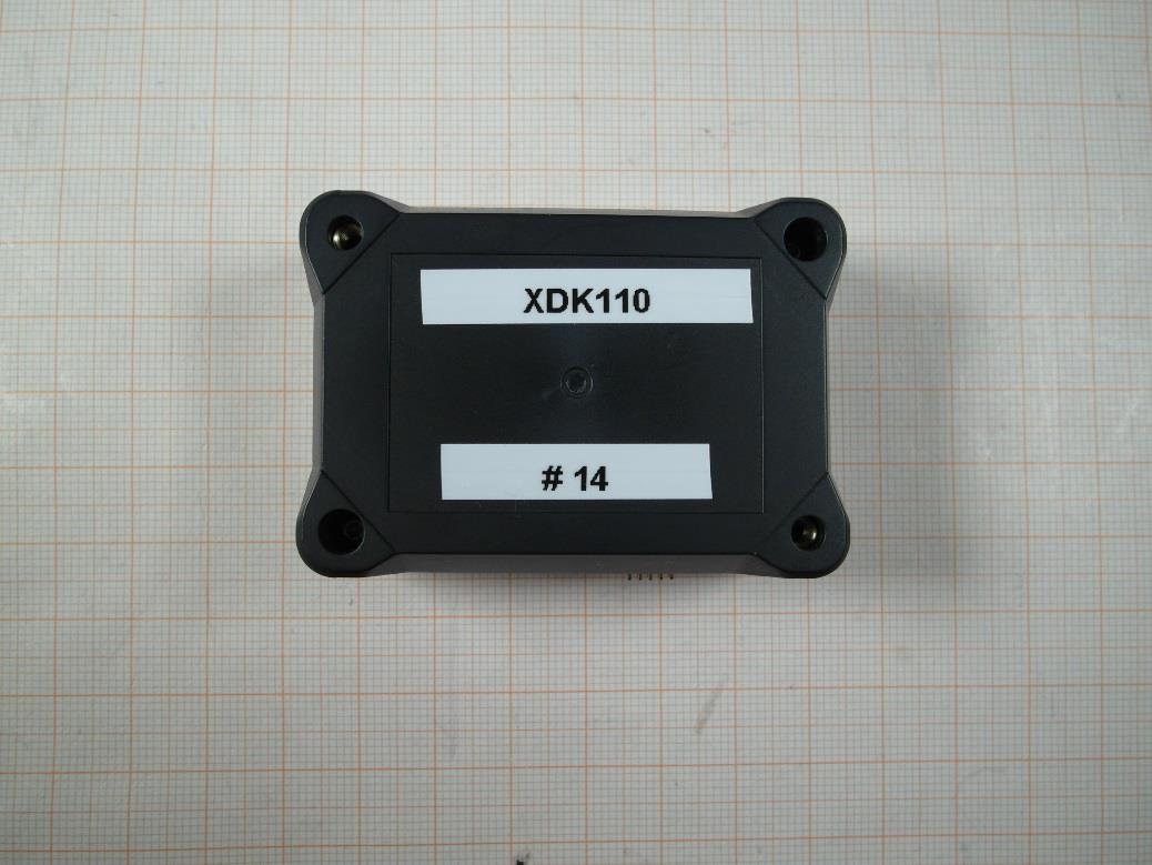
XDK 110 Cross Domain Development Kit Bosch Connected Devices and Solutions GmbH Postfach 13 42 72703 Reutlingen Germany Telephone +49 711 811-0 Fax +49 711 35 1084 www.bosch-connectivity.com Printed in Germany 100 % chlorine free paper de Bedienungsanleitung en Operating Instructions 1 Überblick 1. 1 Einsatzzweck des XDK 110 Das XDK 110 Cross Domain Development Kit ist eine Entwicklungsplatt- form für Anwendungen des „Internets der Dinge“ (IoT) für Windows 7 oder höher. 1.2 Lieferumfang • XDK 110 Development Kit inkl. Lithium-Ionen Akku • Extension-Board mit Leitung 10 cm, 26-polig • Micro USB 2.0 Anschlussleitung • Halteplatte und Schrauben 1.3 Sensorik • BMA280 Beschleunigung • BMG160 Drehrate • BMM150 Magnetfeld • BMI160 Beschleunigung/Drehrate • BME280 Feuchtigkeit/Luftdruck/Temperatur • AKU340 Umgebungslautstärke • MAX44009 Umgebungslicht 1.4 Speicher • Micro-SD-Kartenslot 1.5 Kommunikation • Kabelgebunden: USB 2.0 • Kabellos: Bluetooth; Wireless LAN • LED: 1x grün, 1x gelb, 1x orange, 1x rot Im Anwendungsmodus können Sie die LED Rot, Orange und Gelb ansteuern. 2 | XDK 110deutsch BCDS20141110V1 | 12.2014Bosch Connected Devices and Solutions GmbH 1. 6 Technische Daten BezeichnungWert Temperaturbereich0 – 60 °C Luftfeuchtebis 31 °C max. 80 %; linear fallend auf 50 % bei 40 °C SchutzklasseIP 30 nach IEC 60529 BrandschutzklasseHB (IEC 60695-11-10/-20; CSA C 22.2) Betriebsspannung5 V Gleichspannung Stromstärke 500 mA maximal Kommunikation (kabelgebunden)USB Wireless LANIEEE 802.11 b/g/n Bluetooth 4.0IEEE 802.15.1 1.7 Anschlüsse, Buttons und LED deutsch XDK 110 | 3 Bosch Connected Devices and Solutions GmbHBCDS20141110V1 | 12.2014 USB Power JTAG LED Extension Board Button 1 Button 2 2 Inbetriebnahme und Software Die Software für das XDK 110 ist online verfügbar. Rufen Sie die Seite http://www.xdk.bosch-connectivity.com auf. Unter Downloads finden Sie die aktuelle Version der Softwarepakete sowie Anwendungsbeispiele (Demos). 2.1 Softwaredownload und Installation Laden Sie das Softwarepaket „XDK Workbench“ von der Herstellerweb- site http://www.xdk.bosch-connectivity.com herunter und starten Sie den Installer. Das Softwarepaket enthält alle notwendigen Komponenten sowie Beispiele, Demos und die Toolbox (s. 2.3 Erste Schritte). 2.2 Anschluss des XDK 110 Verbinden Sie das mitgelieferte USB-Kabel mit der USB-Buchse des PC und der Micro-USB-Buchse des XDK 110. Folgende Zustände zeigt das XDK 110 mithilfe der LED: Nach dem ersten Einschalten wird eine Lauflicht-Demo angezeigt. LED Grün: Die grüne LED dient der Lade-Erkennung und kann nicht über Software gesteuert werden. Dauerlicht: Ladend/Temperatursicherheitsschalter ausgelöst Blinkend: Sicherheitszeitschalter ausgelöst Aus: Laden beendet/Akku nicht vorhanden/Fehler in der Span- nungsversorgung/Ladeschaltkreis deaktiviert Wenn das Gerät im Bootloadermodus ist, sind folgende LEDs aktiv: LED Gelb: Dauerlicht: Bootloadermodus aktiv und USB verbunden; Treiber geladen LED Rot: Dauerlicht: Bootloadermodus aktiv Blinken 5x: Keine gültige Anwendung erkannt, XDK bleibt im Bootloadermodus 4 | XDK 110deutsch BCDS20141110V1 | 12.2014Bosch Connected Devices and Solutions GmbH Funktionseinschränkungen Das Gerät kann beeinträchtigt oder beschädigt werden, wenn die Span- nungsversorgung nicht korrekt ist. • Verwenden Sie keine Verbindungsleitungen >┘3 m. • Verwenden Sie nur zertifizierte USB-Ladegeräte Hinweis 2.2.1 Anschluss des Extension-Boards Verbinden Sie die 26-polige Leitung des Extension- Boards mit dem Board und der 26-poligen Buchse des XDK 110. Das Extension-Board bietet eine einfache Möglich- keit, Zusatzfunktionen zu realisieren. Es ist für die Verwendung von Steckplatinen (Breadboards) optimiert. 2.2.2 Anschlussbelegung des Extension-Boards Connec- tor-Pin MCU- Pin Vorgeschla- gene Verwen- dung Connec- tor-Pin MCU- Pin Vorgeschlagene Verwendung A1PA0TIM0_CC0B1PB9UART1_TX (U1_TX) A2PC0TIM0_CC1B2PB10UART1_RX (U1_RX) A3PC1TIM0_CC2B3PB2UART1_RTS A4PC2TIM0_CDTI0B4PF6UART1_CTS A5PC3TIM0_CDTI1B5PB3US2_MOSI (U2_TX) A6PC4TIM0_CDTI2B6PB4US2_MISO (U2_RX) A7PC8TIM2_CC0B7PB5 US2_SCK (US2_ CLK) A8PC9TIM2_CC1B8PD8US2_CS (EXT_CS) A9PC10TIM2_CC2B9PB11I2C1_SDA A10PD5ADC0_CH5B10PB12I2C1_SDL A11PD6ADC0_CH6B112V5 Power Limit 100 mA conti- nuous/peak A12PA1GPIOB123V3 Power Limit 100 mA conti- nuous/peak A13PE1GPIOB13GND Power deutsch XDK 110 | 5 Bosch Connected Devices and Solutions GmbHBCDS20141110V1 | 12.2014 2.3 Erste Schritte • Starten Sie die Software „XDK Workbench“. • Der „Welcome“-Bildschirm erscheint. • Bei angeschlossenem XDK erscheint das XDK-Symbol. • Erstellen Sie Ihre Applikation. • Drücken Sie den „Flash“ Button. Ihre Applikation wird auf das XDK geladen (s. 2.3.1). • Überprüfen Sie die Ausgaben des XDK mithilfe der Konsole der „XDK Workbench“ 2.3.1 Flashen Das XDK 110 lässt sich nur im Bootloader programmieren. Drücken Sie hierzu den „Flash“-Button. Die Software bringt das XDK 110 in den Bootloadermodus, flasht das Programm und bootet das XDK neu. Falls die Software den Bootloadermodus nicht herstellt, kann dies manuell erfolgen: • Schalten sie das XDK aus • Drücken Sie den Button 1 • Halten Sie Button 1 gedrückt und schalten Sie das XDK wieder an. Die rote LED leuchtet auf. Bei bestehender USB-Verbindung leuchtet auch die gelbe LED. Drücken Sie den „Flash“-Button. 2.3.2 Demos Im Softwarepaket sind drei Demos enthalten: • Data Logger: Speichert Sensordaten auf eine Micro-SD Karte • Virtual XDK: Rendert auf einem Tablet ein via Bluetooth verbundenes XDK, das sich analog zum realen XDK bewegt • Sensor Monitor: Darstellung der Rohdaten der Sensoren in 2D-Dar- stellung (Samples über Zeit) 6 | XDK 110deutsch BCDS20141110V1 | 12.2014Bosch Connected Devices and Solutions GmbH 2.3.3 Toolbox Die Toolbox enthält verschiedene Funktionsblöcke und Algorithmen, wie Filter, FFT (Fast Fourier Transform), etc. Mithilfe der Toolbox kann z. B. über die Rohdaten des Drehratensensors und des Beschleunigungssen- sors die Lage im Raum abgeleitet werden. 2.3.4 API-Dokumentat…
Text truncated - open the document above for the full version.
Sicherheitshinweise Das XDK 110 Cross-Domain Development Kit ist eine Entwicklungsplatt- form für Anwendungen des „Internets der Dinge“ (IoT) für Windows 7 oder höher. Es ist für Anwender mit Elektronik- und/oder Programmierer- fahrung konzipiert. Für Schäden, die aus unsachgemäßer Verwendung des Gerätes entstehen, übernehmen wir keine Haftung. XDK 110 deutsch BCDS20141110S1 | 12.2014Robert Bosch GmbH EG-Konformitätserklärung Hersteller: Bosch Connected Devices and Solutions GmbH Tübinger Straße 123 72762 Reutlingen Produkttyp: Cross-Domain Development Kit Bezeichnung: XDK110 Hiermit erklären wir, dass das oben genannte Produkt den einschlägigen Bestimmungen der nachfolgenden Richtlinie(n) entspricht: Richtlinie 1999/5/EG über Funkanlagen und Telekommunikationsend- einrichtungen Richtlinie 2011/65/EU zur Beschränkung der Verwendung bestimmter gefährlicher Stoffe in Elektro- und Elektronikgeräten Bei einer nicht mit uns abgestimmten Änderung des Produkts verliert diese Erklärung ihre Gültigkeit. Folgende harmonisierte Normen wurden angewandt: EN 300 328 1.8.1, EN 301 489-1/-17, EN 55022, EN 55024, EN 60950-1, EN 62311 Datum Unterschrift(Position) XDK 110deutsch Hinweis Kurzschlussgefahr! Eindringende Flüssigkeit kann das Gerät beschädigen und Kurzschlüsse auslösen. In diesem Fall besteht Brandgefahr. • Lassen Sie keine Flüssigkeiten in das XDK 110 eindringen. • Betreiben Sie das Gerät nur innerhalb angegebenen Spezifikationen. Hinweis Garantieverlust! Durch unbefugtes Öffnen des Gehäuses können Gefahren für den Benutzer entstehen.Der Garantieanspruch erlischt. • Öffnen Sie das Gehäuse nicht. • Verwenden Sie nur originales oder freigegebenes Zubehör. Hinweis Lithium-Ionen-Akku Das Gerät enthält einen Lithium-Ionen-Akku. Unsachgemäße Behandlung kann zu einem Brand führen. • Schützen Sie das XDK 110 vor Schlägen oder Stößen • Beachten Sie gegebenenfalls die geltenden Transportvorschriften Zu hohe Sendeleistung Das Gerät ist für die Verwendung von Bluetooth und WLAN mittels der mitgelieferten Software-Bibliotheken ausgelegt. Für die Ansteuerung der Funkschnittstellen dürfen keine Änderungen an den Funkprotokollen und der Hardware durchgeführt werden. Personen- und Sachschäden können die Folge sein Bei einer solchen Änderung erlöschen zudem die Garantie und die Konformitätserklärung. • Verändern Sie niemals die Software-Stacks der Funkschnittstellen. Hinweis Hinweis Funktionseinschränkungen Das Gerät kann beeinträchtigt oder beschädigt werden, wenn die Span- nungsversorgung nicht korrekt ist. • Verwenden Sie keine Verbindungsleitungen >┘3 m. • Verwenden Sie nur zertifizierte USB-Ladegeräte BCDS20141110S1 | 12.2014Robert Bosch GmbH Safety Instructions The XDK 110 Cross-Domain Development Kit is a development platform for Internet of Things (IoT) use cases. It works with Windows 7 or higher. It is designed for users with experience in electronics or programming. We do not assume any liability for damages which occur as the result of improper use of the device. XDK 110 english BCDS20141110S1 | 12.2014Robert Bosch GmbH Declaration of Conformity Manufacturer: Bosch Connected Devices and Solutions GmbH Tübinger Straße 123 72762 Reutlingen Product Type: Cross-Domain Development Kit Product Name: XDK110 We hereby declare that the product described above complies with the relevant clauses of the following directive(s): Directive 2011/65/EU on the restriction of the use of certain hazardous substances in electrical and electronic equipment Directive 1999/5/EC on radio equipment and telecommunications terminal equip- ment Any modification to the product not expressly approved by the manufacturer shall void the validity of this declaration. The following harmonised standard have been applied: EN 300 328 1.8.1, EN 301 489-1/-17, EN 55022, EN 55024, EN 60950-1, EN 62311 FCC Declaration of Conformity NOTE: This equipment has been tested and found to comply with the limits for a Class B digital device, pursuant to Part 15 of the FCC Rules. These limits are designed to provide reasonable protection against harmful interference in a residential installation. This equipment generates, uses and can radiate radio frequency energy and, if not installed and used in accordance with the instructions, may cause harmful interference to radio communications. However, there is no guarantee that interfe- rence will not occur in a particular installation. If this equipment does cause harmful interference to radio or television reception, which can be determined by turning the equipment off and on, the user is encouraged to try to correct the interference by one or more of the following measures: • Reorient or relocate the receiving antenna. • Increase the separation between the equipment and receiver. • Connect the equipment into an outlet on a circuit different from that to which the receiver is connected. • Consult the dealer or an experienced radio/TV technician for help. Declaration of Conformity Canada This Class B digital apparatus complies with Canadian ICES-003. Cet appareil numérique de la classe B est conforme à la norme NMB-003 du Canada. Date Sign, position XDK 110english BCDS20141110S1 | 12.2014Robert Bosch GmbH Too Much Transmission Power The device is designed for use with the delivered software library only. It is not allowed to make any change on radio protocols or hardware for radio interface control. This could cause personal injury or damage to materials. Such a change also voids the warranty, declaraction of conformity and FCC authorization to operate this equipment. • Never change the software stacks of the radio interface notice Risk of Short Circuits! Penetrating fluids can damage the device and cause short circuits. This could present the risk of fire. • Do not allow any fluids to penetrate the XDK 110. • Use the device only as specified in the manual. notice Lithium-Ion Battery! The device contains a lithium-ion battery. Handling the battery incorrectly could cause a fire. • Protect the XDK 110 fro…
Text truncated - open the document above for the full version.
Test report no.: 1-8300/14-01-01_AnnexA Page 1 of 6 Annex A This test report annex is electronically signed and valid without handwriting signature. For verification of the electronic signatures, the public keys can be requested at the testing laboratory. Test report annex authorised: Andreas Luckenbill Radio Communications & EMC Test report no.: 1-8300/14-01-01_AnnexA Page 2 of 6 External ph ot os o f t he EU T Photo 1: Photo 2: Test report no.: 1-8300/14-01-01_AnnexA Page 3 of 6 Photo 3: Photo 4: Test report no.: 1-8300/14-01-01_AnnexA Page 4 of 6 Photo 5: Photo 6: Test report no.: 1-8300/14-01-01_AnnexA Page 5 of 6 Photo 7: Test report no.: 1-8300/14-01-01_AnnexA Page 6 of 6 Docu men t his to r y Version Applied changes Date of release Initial release 2015-01-21
! " # $ % $ $ & $ % $ % ' ( & )( & $ ($ & %& $ & * (( $ $ ($ ($ ' $ % " +, - . / %0 12 ,11 3+45 2 -6 7 $ 0 47 !! 8 %$ 9 : ; " < = > ?( 0 $ " @ '@ .9 2 @7 A @ ; B = $ C / % 7 $ ' 7#9 #$ ; -& B-#= ( 0 19 -% D9 -% ?! !$ % $ $ Bosch Connected Devices and Solutions FCC ID: 2ADSJXDK110IC ID: 12595A-XDK110 M/N: XDK110 Made in Germany serial #: 15-00000 WLAN: 00-00-00-00-00 Bluetooth: 00-00-00-00-00 $ $ 0 EE9 " " EE9 FFFFF ; G $ % = 5V 0.5A max ! " # $ % $ $ & $ % $ % ' ( & )( & $ ($ & %& $ & * (( $ $ ($ ($ ' $ % " +, - ' Bosch Connected Devices and Solutions Made in Germany serial #: 15-00000 WLAN: 00-00-00-00-00 Bluetooth: 00-00-00-00-00 $ $ 0 EE9 " " EE9 FFFFF ; G $ % = 5V 0.5A max M/N: XDK110 Label areaOn backside of housing XDK110
Test report no.: 1-8300/14-01-01_AnnexB Page 1 of 6 Annex B This test report annex is electronically signed and valid without handwriting signature. For verification of the electronic signatures, the public keys can be requested at the testing laboratory. Test report annex authorised: Andreas Luckenbill Radio Communications & EMC Test report no.: 1-8300/14-01-01_AnnexB Page 2 of 6 Inter nal p ho tos of the E UT Photo 1: Photo 2: Test report no.: 1-8300/14-01-01_AnnexB Page 3 of 6 Photo 3: Photo 4: Test report no.: 1-8300/14-01-01_AnnexB Page 4 of 6 Photo 5: Photo 6: Test report no.: 1-8300/14-01-01_AnnexB Page 5 of 6 Photo 7: Test report no.: 1-8300/14-01-01_AnnexB Page 6 of 6 Docu men t his to r y Version Applied changes Date of release Initial release 2015-01-21
FCC ID: 2ADSJXDK110 IC: 12595A-XDK110 Model: XDK110 Prediction of MPE limit at given distance Equation from page 18 of OET Bulletin 65, Edition 97-01 S = PG / 4π R 2 where: S = Power density P = Power input to the antenna G = Antenna gain R = Distance to the center of radiation of the antenna The table below is excerpted from Table 1B of 47 CFR 1.1310 titled “Limits for Maximum Permissible Exposure (MPE), Limits for General Population/Uncontrolled Exposure” Frequency Range (MHz) Power Density (mW/cm 2 ) Averaging Time (minutes) 300 -1500 f/1500 30 1500 - 100000 1.0 30 where f = Frequency (MHz) Calculation: Antenna 1 Antenna 2 P Max power input to the antenna: 17.25 dBm / 53.1 mW 3 dBm / 2 mW R Distance: 20 cm 20 cm S MPE limit for uncontrolled exposure 1 mW/cm 2 1 mW/cm 2 G Antenna Gain: 1.91 numerical 2.24 numerical Calculated Power density 0.02 mW/cm 2 0.0009 % MPE 2% 0.1% Max % MPE: 2.1 % This prediction demonstrates the following: The power density levels at a distance of 20 cm are below the maximum levels allowed by regulations. Andreas Luckenbill Cetecom ICT Services GmbH
TEST REPORT Test report no.: 1-8300/14-01-09 Testing laboratory Applicant CETECOM ICT Services GmbH Untertuerkheimer Strasse 6 – 10 66117 Saarbruecken / Germany Phone: + 49 681 5 98 - 0 Fax: + 49 681 5 98 - 9075 Internet: http://www.cetecom.com e-mail: [email protected] Accredited Testing Laboratory: The testing laboratory (area of testing) is accredited according to DIN EN ISO/IEC 17025 (2005) by the Deutsche Akkreditierungsstelle GmbH (DAkkS) The accreditation is valid for the scope of testing procedures as stated in the accreditation certificate with the registration number: D-PL-12076-01-00 Bosch Connected Devices and Solutions GmbH Tuebinger Str. 123 72762 Reutlingen / GERMANY Phone: +49 (711) 811-3617318 Fax: +49 (711) 811-5183788 Contact: Mathias Bruendel e-mail: [email protected] Phone: +49 (711) 811-3617318 Manufacturer Bosch Connected Devices and Solutions GmbH Tuebinger Str. 123 72762 Reutlingen / GERMANY Test standard/s 47 CFR Part 15 Title 47 of the Code of Federal Regulations; Chapter I; Part 15 - Radio frequency devices RSS - 210 Issue 8 Spectrum Management and Telecommunications Radio Standards Specification - Licence-exempt Radio Apparatus (All Frequency Bands): Category I Equipment For further applied test standards please refer to section 3 of this test report. Test Item Kind of test item: Development Kit Model name: XDK110 FCC ID: 2ADSJXDK110 IC: 12595A-XDK110 Frequency: DTS band 2.4 GHz lowest channel: 2402 MHz; highest channel: 2480 MHz Technology tested: Bluetooth® Low Energy Antenna: Integrated antenna Power supply: 3.7V DC by Li-polymer battery Temperature range: 0°C to +60°C This test report is electronically signed and valid without handwriting signature. For verification of the electronic signatures, the public keys can be requested at the testing laboratory. Test report authorised: Test performed: Andreas Luckenbill Joerg Warken Radio Communications & EMC Radio Communications & EMC Test report no.: 1-8300/14-01-09 Page 2 of 52 1 Table of contents 1 Table of contents ............................................................................................................................................ 2 2 General information ....................................................................................................................................... 3 2.1 Notes and disclaimer .......................................................................................................................... 3 2.2 Application details ............................................................................................................................... 3 3 Test standard/s ............................................................................................................................................... 3 3.1 Measurement guidance ....................................................................................................................... 3 4 Test environment ............................................................................................................................................ 4 5 Test item .......................................................................................................................................................... 4 5.1 Additional information ........................................................................................................................ 4 6 Test laboratories sub-contracted ................................................................................................................. 4 7 Description of the test setup ......................................................................................................................... 5 7.1 Radiated measurements chamber F .................................................................................................. 5 7.2 Radiated measurements chamber C ................................................................................................. 6 7.3 Radiated measurements 12.75 GHz to 26 GHz ................................................................................. 7 7.4 AC conducted ...................................................................................................................................... 8 7.5 Conducted measurements ................................................................................................................. 9 8 Summary of measurement results ............................................................................................................. 10 9 Additional comments ................................................................................................................................... 11 10 Measurement results ................................................................................................................................ 12 10.1 Antenna gain .................................................................................................................................. 12 10.2 Power spectral density .................................................................................................................. 13 10.3 DTS bandwidth – 6 dB bandwidth ................................................................................................ 16 10.4 Occupied bandwidth – 20 dB bandwidth ..................................................................................... 19 10.5 Maximum output power ................................................................................................................. 22 10.6 Detailed spurious emissions @ the band edge - conducted .................................................... 25 10.7 Band edge compliance radiated ................................................................................................... 27 10.8 TX spurious emissions conducted ......................................................................................…
Text truncated - open the document above for the full version.
TEST REPORT Test report no.: 1-8300/14-01-10 Testing laboratory Applicant CETECOM ICT Services GmbH Untertuerkheimer Strasse 6 – 10 66117 Saarbruecken / Germany Phone: + 49 681 5 98 - 0 Fax: + 49 681 5 98 - 9075 Internet: http://www.cetecom.com e-mail: [email protected] Accredited Testing Laboratory: The testing laboratory (area of testing) is accredited according to DIN EN ISO/IEC 17025 (2005) by the Deutsche Akkreditierungsstelle GmbH (DAkkS) The accreditation is valid for the scope of testing procedures as stated in the accreditation certificate with the registration number: D-PL-12076-01-00 Bosch Connected Devices and Solutions GmbH Tuebinger Str. 123 72762 Reutlingen / GERMANY Phone: +49 (711) 811-3617318 Fax: +49 (711) 811-5183788 Contact: Mathias Bruendel e-mail: [email protected] Phone: +49 (711) 811-3617318 Manufacturer Bosch Connected Devices and Solutions GmbH Tuebinger Str. 123 72762 Reutlingen / GERMANY Test standard/s 47 CFR Part 15 Title 47 of the Code of Federal Regulations; Chapter I; Part 15 - Radio frequency devices RSS - 210 Issue 8 Spectrum Management and Telecommunications Radio Standards Specification - Licence-exempt Radio Apparatus (All Frequency Bands): Category I Equipment For further applied test standards please refer to section 3 of this test report. Test Item Kind of test item: Development Kit Model name: XDK110 FCC ID: 2ADSJXDK110 IC: 12595A-XDK110 Frequency: DTS band 2.4 GHz Lowest channel: 2412 MHz; highest channel: 2462 MHz Technology tested: WLAN (b/g/n) Antenna: Integrated chip antenna Power supply: 3.7V DC by Li-polymer battery Temperature range: 0°C to +60°C This test report is electronically signed and valid without handwriting signature. For verification of the electronic signatures, the public keys can be requested at the testing laboratory. Test report authorised: Test performed: Stefan Bös Andreas Luckenbill Radio Communications & EMC Radio Communications & EMC Test report no.: 1-8300/14-01-10 Page 2 of 81 1 Table of contents 1 Table of contents ............................................................................................................................................ 2 2 General information ....................................................................................................................................... 3 2.1 Notes and disclaimer .......................................................................................................................... 3 2.2 Application details ............................................................................................................................... 3 3 Test standard/s ............................................................................................................................................... 3 3.1 Measurement guidance ....................................................................................................................... 3 4 Test environment ............................................................................................................................................ 4 5 Test item .......................................................................................................................................................... 4 5.1 Additional information ........................................................................................................................ 4 6 Test laboratories sub-contracted ................................................................................................................. 4 7 Description of the test setup ......................................................................................................................... 5 7.1 Radiated measurements chamber F .................................................................................................. 5 7.2 Radiated measurements chamber C ................................................................................................. 6 7.3 Radiated measurements 12.75 GHz to 26 GHz ................................................................................. 7 7.4 AC conducted ...................................................................................................................................... 8 7.5 Conducted measurements ................................................................................................................. 9 8 Summary of measurement results ............................................................................................................. 10 9 Additional comments ................................................................................................................................... 11 10 Measurement results ................................................................................................................................ 12 10.1 Antenna gain .................................................................................................................................. 12 10.2 Identify worst case data rate ......................................................................................................... 15 10.3 Maximum output power ................................................................................................................. 16 10.4 Power spectral density .................................................................................................................. 17 10.5 Spectrum bandwidth – 6 dB .......................................................................................................... 24 10.6 Occupied bandwidth – 99% emission bandwidth....................................................................... 25 10.7 Detailed spurious emissions @ the band edge - conducted .................................................... 32 10.8 Band edge compliance radiated ...........................................................................................…
Text truncated - open the document above for the full version.
Test report no.: 1-8300/14-01-01_AnnexD Page 1 of 6 Annex D This test report annex is electronically signed and valid without handwriting signature. For verification of the electronic signatures, the public keys can be requested at the testing laboratory. Test report annex authorised: Andreas Luckenbill Radio Communications & EMC Test report no.: 1-8300/14-01-01_AnnexD Page 2 of 6 EUT Test se tu p p h otos Photo 1: Photo 2: Test report no.: 1-8300/14-01-01_AnnexD Page 3 of 6 Photo 3: Photo 4: Test report no.: 1-8300/14-01-01_AnnexD Page 4 of 6 Photo 5: Photo 6: Test report no.: 1-8300/14-01-01_AnnexD Page 5 of 6 Photo 7: Photo 8: Test report no.: 1-8300/14-01-01_AnnexD Page 6 of 6 Docu men t his to r y Version Applied changes Date of release Initial release 2015-01-21
| # | Rule Parts | Frequency Range | Power Output |
|---|---|---|---|
| 2 | 15C | 2.40 GHz - 2.48 GHz | 1.00 mW |

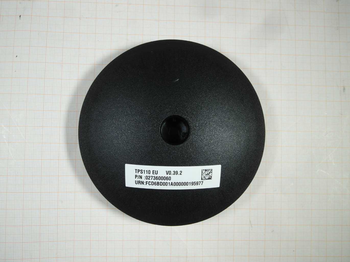
Parking Lot Sensor
Equipment Class
DSS - Part 15 Spread Spectrum Transmitter