2ADTD-M040101211Single Input Transmitter
Hangzhou Hikvision Digital Technology Co., Ltd.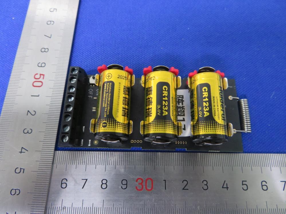
Click to zoom
Application Details
- Equipment Class
- DSR - Part 15 Remote Control/Security Device Transceiver
- Date of Grant
- Jul 07, 2021
- Application Purpose
- Original Equipment
- Date of Application
- Jul 01, 2021
- Equipment Note
- Single Input Transmitter
- Frequency Range
- 433.10000000 - 433.70000000
- Country
- China
Documents & Files
Document Text
Text extracted from the exhibit documents filed with the FCC. Open a document above to read the original.
Users Manual
Single Input Transmitter DS-PM1-I1-WB User Manual Hangzhou Hikvision Digital Technology CO.,Ltd. No.555 Qianmo Road, Binjiang District, Hangzhou 310052, China Overview Appearance Enrollment Installation and Wiring ON OFF ZONE TAMP AM/O + - CR123A CR123A CR123A ON OFF ZONE TAMP AM/OUT + - CR123A CR123A CR123A 1 2 3 6 4 5 1 xxxx Device 2 3 ON OFF ZONE TAMP AM/O + - CR123A ZONE TAMP AM/O + - ON OFF ZONE TAMP AM/OUT + - a b c d +- +- +- 7 Times The transmitter makes the third-party wired detectors be able to connect to the AXPRO intrusion alarm system. It supports tampering alarm and can supply power to the connected peripherals. 1.Battery Holder. 2.Enrollment Indicator. 3.Alarm Indicator 5.Zone input/Tamper input/AM or OUT/3.3V power 6.Power Switch. a.Zone Input Wiring b.Tampering Alarm Wiring c.AM/ O:Anti masking / Output d.Power Supply Wiring (3.3V) Enrollment procedure: Solid green for 1s-->Flashing red and green-->Flashing green for 7 times Alarm alarm: Solid red for 2s Fault alarm: Solid amber 4.Fault Indicator Note:If the device has no response when power on, connect the two terminals of Zone Input and power the device on again. UD23557B RF Frequency433MHz Modulation2GFSK MethodTwo-way communication RF Distance1300 m (open area) Input1 Alarm, 1 Tamper PGM1, AM/Output 3.3v output1, up to 10mA Power Switch1 Series Port1 LED Status 3: Alarm/TamperRed, Fault Amber, Signal StrengthGreen/Red Power Supply3 CR123, 3V Power Output3.21V to 3.35V, Rated: 3.3V Consumption Max. current: 47.85mA, Quiescent current: 40.29uA Voltage: 3 VDC Operation temperature –10to 55 Operation humidity10% to 90% Dimension (W x H x D) 102 x 41 x 20mm Weight35g (Without Battery), 90g (With Battery) InstallationPut inside Wireless Ready Detector Español Descripción general El transmisor permite que los detectores por cable de otras marcas se conecten al sistema a alarma de intrusión AXPRO. Es compatible con la alarma de manipulación y puede suministrar alimentación a los periféricos conectados. Apariencia 1.Soporte de batería. 2.Indicador de registro. Procedimiento de registro: Verde fijo durante 1 s --> Parpadeo en rojo y verde --> Parpadeo en vede 7 veces 3.Piloto de alarma Alarma: Rojo fijo durante 2 s 4.Indicador de fallo Alarma de fallo: Ámbar fijo 5.Entrada de zona/Entrada manipulación/AM o OUT/ Alimentación de 3,3 V 6.Interruptor de alimentación. Registro Instalación y cableado a.Cableado de entrada de zona b.Cableado de alarma de manipulación c. AM/OUT: Antienmascaramiento/Salida d.Cableado de alimentación (3,3 V) Especificación Frecuencia de RF Modulación Método Distancia de radiofrecuencia Entrada PGM Salida de 3,3 V Interruptor de alimentación Puerto serie Estado del led Fuente de alimentación Salida de alimentación Consumo Temperatura de funcionamiento Humedad de funcionamiento Dimensiones Peso Instalación 868 MHz 2GFSK Comunicación bidireccional 1600 m (área abierta) 1 Alarma, 1 Manipulación 1, AM/Salida 1,hasta 10 mA 1 1 3: Alarma/Manipulación (Rojo), Fallo (Ámbar), Fuerza de la señal (Verde/Rojo) 3 CR123, 3 V de 3,21 V a 3,35V, Nominal: 3,3 V Corriente máx.: 47,85 mA, Corriente de reposo: 40,29 μA Tensión: 3 VCC -10 °C a 55 °C 10 % a 90 % 102 x 41 x 20 mm 35 g (sin batería), 90 g (con batería) Colocar dentro del detector inalámbrico ya instalado Nota:Si el dispositivo no responde al encenderlo, conecte los dos terminales de la entrada de zona y vuelva a encender el dispositivo. 868 MHz 2GFSK Comunicação bidirecional 1.600 m (área aberta) 1 alarme, 1 violação 1, AM/saída 1, até 10 mA 1 1 3: Alarme/violação (vermelho), falha (laranja), intensidade do sinal (verde/vermelho) 3 CR123, 3 V 3,21 V a 3,35 V; nominal: 3,3 V Corrente máx.: 47,85 mA, Corrente quando inativo: 40,29 μA Tensão: 3 VCC -10 °C a 55 °C 10% a 90% 102 x 41 x 20 mm 35 g (sem bateria), 90 g (com bateria) Coloque dentro do detector sem fio já instalado Observação:se o dispositivo não responder ao ser ligado, conecte os dois terminais da entrada de zona e ligue-o novamente. Português Visão geral O transmissor permite que detectores com fio de terceiros se conectem ao sistema de alarme de intrusão AXPRO. É compatível com alarme de violação e pode fornecer energia aos periféricos conectados. Apresentação 1.Compartimento da bateria. 2.Indicador de registro. Procedimento de registro: Verde fixo por 1 s --> Piscando em vermelho e verde --> Piscando em verde 7 vezes 3.Indicador de alarme Alarme: vermelho fixo por 2 s 4.Indicador de falha Alarme de falha: laranja fixo 5.Entrada de zona/entrada de violação/AM ou OUT/ alimentação de 3,3 V 6.Interruptor de energia. Registro Instalação e cabeamento a.Fiação de entrada de zona b.Fiação de alarme de violação c. AM/OUT: antimascaramento/saída d.Fonte de alimentação (3,3 V) Especificações Frequência de RF Modulação Método Distância de RF Entrada PGM Saída de 3,3 V Interruptor Porta serial Status do LED Fonte de alimentação Saída de alimentação Consumo Temperatura de operação Umidade de operação Dimensões (L x A x P) Peso Instalação Slovenščina Pregled Oddajnik omogoča, da se žični detektorji tretjih oseb lahko povežejo z alarmnim sistemom AXPRO. Podpira alarm za nedovoljeno poseganje in lahko napaja priključene zunanje naprave. Pregled naprave 1.Držalo za baterijo. 2.Indikator vpisa. Postopek vpisa: Zelena gori 1 s-->Utripata rdeča in zelena-->Zelena utripne 7-krat 3.Indikator alarma Alarm: Rdeča gori 2 s 4.Indikator napake Alarm za napako: Gori jantarna 5.Vhod za cono/Vhod za nedovoljeno poseganje/ AM ali OUT/Moč 3,3 V 6.Stikalo za vklop. Vpis Namestitev in ožičenje a.Ožičenje vhoda za cono b.Ožičenje alarma za nedovoljeno poseganje c. AM/OUT: Anti-maskiranje/Izhod d.Ožičenje napajanja (3,3 V) Tehnični podatki RF-frekvenca Modulacija Metoda Razdalja RF Vhod PGM Izhod 3,3 v Stikalo za vklop/izklop Serijska vrata Stanje LED Napajanje Izhodna moč Poraba Operativna temperatura Operativna vlažnost Dimenzije (Š x V x G) Teža Namestitev 868 MHz 2GFSK Dvosmerna komunikacija 1600 m (odprto območje) 1 alarm, 1 nedov…
Text truncated - open the document above for the full version.
Cover Letter(s)
QF094234 Page 1 of 1 Revision 0 Authority to Act as Agent Date: _2020-10-20_______ TUV Rheinland Group 762 Park Avenue Youngsville, NC 27596 To Whom It May Concern: I appoint TUV Rheinland (Shenzhen) Co., Ltd Mr Bell Hu to act as our agent in the preparation of this application for equipment certification. I certify that submitted documents properly describe the device or system for which equipment certification is sought. I also certify that each unit manufactured, imported or marketed, as defined in the FCC or Industry Canada’s regulations will have affixed to it a label identical to that submitted for approval with this application. For instances where our authorized agent signs the application for certification on our behalf, I acknowledge that all responsibility for complying with the terms and conditions for Certification, as specified by TUV Rheinland Group For TCB applications, We certify that we are not subject to denial of federal benefits, that includes FCC benefits, pursuant to Section 5301 of the Anti-Drug Abuse Act of 1988, 21 U.S.C. 862. Further, no party, as defined in 47 CFR 1.2002 (b), to the application is subject to denial of federal benefits, that includes FCC benefits. Thank you, Agency Agreement Expiration Date: _____ 12 months____ By: Xiuying Zhang (Signature) (Print name) Title: ____ Telephone On behalf of: Hangzhou Hikvision Digital Technology Co.,Ltd. (Company Name)
Cover Letter(s)
Confidentiality Letter Date: 2020-10-20 Subject: Confidentiality Request Pursuant to FCC 47 CRF 0.457(d) and 0.459 and IC RSP-100, Section 10, the applicant requests that a part of the subject FCC/IC application be held confidential. Type of Confidentiality Requested Exhibit Short Term Permanent Block Diagrams Short Term Permanent External Photos Short Term Permanent Internal Photos Short Term Permanent Operation Description/Theory of Operation Short Term Permanent Part List/Tune-Up Procedure Short Term Permanent Schematics Short Term Permanent Test Setup Photos Short Term Permanent User’s Manual Hangzhou Hikvision Digital Technology Co.,Ltd. has spent substantial effort in developing this product and it is one of the first of its kind in industry. Having the subject information easily available to "competition" would negate the advantage they have achieved by developing this product. Not protecting the details of the design will result in financial hardship. Permanent Confidentiality: The applicant requests the exhibits listed above as permanently confidential be permanently withheld from public review due to materials that contain trade secrets and proprietary information not customarily released to the public. Short-Term Confidentiality: The applicant requests the exhibits selected above as short term confidential be withheld from public view for a period of 180 days from the date of the Grant of Equipment Authorization and prior to marketing. This is to avoid premature release of sensitive information prior to marketing or release of the product to the public. Applicant is also aware that they are responsible to notify TUV Rheinland in the event information regarding the product or the product is made available to the public. TUV Rheinland will then release the documents listed above for public disclosure pursuant to FCC Public Notice DA 04- 1705. Sincerely, By: (Signature/Title) (Print name)
External Photos
External Photo Rev. 0 External Photo Rev. 0 External Photo Rev. 0
ID Label/Location Info
FCC ID: 2ADTD-M040101211 Label and Label Location Location: above label will be attached to back of EUT’s PCBA.
Internal Photos
Internal Photo Rev. 0 Internal Photo Rev. 0
RF Exposure Info
FCC ID: 2ADTD-M040101211 Radio Frequency Exposure Compliance RESULT: Pass Test Specification Test standard : CFR47 FCC Part 2.1093 Limit : FCC KDB Publication 447498 D01 v06 Measurement Record for CFR47 FCC Part 2.1093 The minimum distance for the EUT is less than 5mm. The maximum specified e.r.p.: 81.67dBuV/m@3m=-13.56dBm=0.044mW According to KDB 447498 D01 v06 appendix A Exempted Power for this device: 22mW, hence the EUT is compliance with the RF exposure.
Test Report
Prüfbericht - Produkte Test Report - Products Prüfbericht-Nr.: Test report no.: CN212GVU 001 Auftrags-Nr.: Order no.: 168320011 Seite 1 von 17 Page 1 of 17 Kunden-Referenz-Nr.: Client reference no.: N/A Auftragsdatum: Order date: 2021-05-25 Auftraggeber: Client: Hangzhou Hikvision Digital Technology Co., Ltd. No.555 Qianmo Road, Binjiang District, Hangzhou 310052, China Prüfgegenstand: Test item: Single Input Transmitter Bezeichnung / Typ-Nr.: Identification / Type no.: DS-PM1-I1-WB, DS-PM1-I1-WBUHK, DS-PM1-I1-WBCKV, DS-PM1-I1-WBUVS, DS-PM1-I1-WBKVO, DS-PM1-I1-WBHUN Auftrags-Inhalt: Order content: Test Report Prüfgrundlage: Test specification: FCC 47 CFR Part 15.203 FCC 47 CFR Part 15.231 FCC 47 CFR Part 2.1093 Wareneingangsdatum: Date of sample receipt: 2021-05-27 Refer to Photo Documentation Prüfmuster-Nr.: Test sample no: A003058387-005~006 A003058387-020~024 Prüfzeitraum: Testing period: 2021-05-28 to 2021-06-21 Ort der Prüfung: Place of testing: TÜV Rheinland (Shenzhen) Co., Ltd. Prüflaboratorium: Testing laboratory: TÜV Rheinland (Shenzhen) Co., Ltd. Prüfergebnis*: Test result*: Pass geprüft von: tested by: X genehmigt von: authorized by: X Datum: Date: 2021-06-23 Ausstellungsdatum: Issue date: 2021-06-23 Stellung / Position: Sachverständige(r) / Expert Stellung / Position: Sachverständige(r) / Expert Sonstiges / Other: FCC ID: 2ADTD-M040101211 FCC 47 CFR Part 2.1093 is not in the A2LA accreditation scope, because the product complies with requirements of test standard FCC 47 CFR Part 2.1093 by calculated method, not involves testing. Zustand des Prüfgegenstandes bei Anlieferung: Condition of the test item at delivery: Prüfmuster vollständig und unbeschädigt Test item complete and undamaged * Legende: 1 = sehr gut 2 = gut 3 = befriedigend 4 = ausreichend 5 = mangelhaft P(ass) = entspricht o.g. Prüfgrundlage(n) F(ail) = entspricht nicht o.g. Prüfgrundlage(n) N/A = nicht anwendbar N/T = nicht getestet * Legend: 1 = very good 2 = good 3 = satisfactory 4 = sufficient 5 = poor P(ass) = passed a.m. test specification(s) F(ail) = failed a.m. test specification(s) N/A = not applicable N/T = not tested Dieser Prüfbericht bezieht sich nur auf das o.g. Prüfmuster und darf ohne Genehmigung der Prüfstelle nicht auszugsweise vervielfältigt werden. Dieser Bericht berechtigt nicht zur Verwendung eines Prüfzeichens. This test report only relates to the a. m. test sample. Without permission of the test center this test report is not permitted to be duplicated in extracts. This test report does not entitle to carry any test mark. TÜV Rheinland (Shenzhen) Co., Ltd. 1601 R&D Room, 1602-1604, 17-18F, Building 7 Site C, Vanke Cloud City Phase I, Xingke First Street, Xili Street, Xili Community, Nanshan District, Shenzhen 518052, P.R. China Mail: [email protected] · Web: www.tuv.com jjj Hardy Suo Andy Yan Prüfbericht - Produkte Test Report - Products Prüfbericht - Nr.: Test Report No. CN212GVU 001 Seite 2 von 17 Page 2 of 17 TEST SUMMARY 5.1.1 Antenna Requirement RESULT: Pass 5.1.2 Deactivation of the Transmission RESULT: Pass 5.1.3 Periodic Transmissions RESULT: Pass 5.1.4 20dB Emission Bandwidth RESULT: Pass 5.1.5 Field strength of fundamental and Unwanted Emissions in the Spurious Domain RESULT: Pass 5.1.6 Radio Frequency Exposure Compliance RESULT: Pass Prüfbericht - Produkte Test Report - Products Prüfbericht - Nr.: Test Report No. CN212GVU 001 Seite 3 von 17 Page 3 of 17 CONTENTS 1. GENERAL REMARKS ............................................................................................................ 4 1.1 COMPLEMENTARY MATERIALS ........................................................................................ 4 1.2 TEST STANDARD(S) ....................................................................................................... 4 2. TEST SITES ......................................................................................................................... 4 2.1 TEST FACILITIES ............................................................................................................ 4 2.2 TEST DATE ................................................................................................................... 4 2.3 LIST OF TEST AND MEASUREMENT INSTRUMENTS ............................................................ 5 2.4 TRACEABILITY ............................................................................................................... 6 2.5 CALIBRATION ................................................................................................................ 6 2.6 LOCATION OF ORIGINAL DATA ........................................................................................ 6 2.7 STATUS OF FACILITY USED FOR TESTING ........................................................................ 6 3. GENERAL PRODUCT INFORMATION ....................................................................................... 7 3.1 PRODUCT FUNCTION AND INTENDED USE ....................................................................... 7 3.2 RATINGS AND SYSTEM DETAILS...................................................................................... 7 3.3 INDEPENDENT OPERATION MODES ................................................................................. 7 3.4 NOISE GENERATING AND NOISE SUPPRESSING PARTS .................................................... 8 3.5 SUBMITTED DOCUMENTS ............................................................................................... 8 4. TEST SET-UP AND OPERATION MODES ................................................................................. 9 4.1 PRINCIPLE OF CONFIGURATION SELECTION ..................................................................... 9 4.2 TEST OPERATION AND TEST SOFTWARE ......................................................................... 9 4.3 SPECIAL ACCESSORIES AND AUXILIARY EQUIPMENT ........................................................ 9 4.4 COUNTERMEASURES TO ACHIEVE ERM COMP…
Text truncated - open the document above for the full version.
Test Setup Photos
Prüfbericht - Produkte Test Report - Products Appendix B CN212GVU 001 Page 1 of 2 Appendix B: Photographs of the Test Set-Up APPENDIX B: PHOT OGRAPHS OF T HE TEST SET-UP ......................................................................... 1 APPENDIX B.1: SET-UP FOR RA DIATED EMISSIONS, BELOW 1 GHZ ................................................... 2 APPENDIX B.2: SET-UP FOR RA DIATED EMISSIONS, ABOV E 1 GHZ ................................................... 2 Prüfbericht - Produkte Test Report - Products Appendix B CN212GVU 001 Page 2 of 2 Appendix B.1: Set-up for Radiated Emissions, below 1 GHz Appendix B.2: Set-up for Radiated Emissions, above 1 GHz
Contact Information
Applicant
Long Cheng
Technical Contact
Test Firm
TUV Rheinland (Shenzhen) Co., Ltd.Gina Yang
[email protected]86 755 8268 1497
Technical Specifications
| # | Rule Parts | Frequency Range | Power Output |
|---|---|---|---|
| 1 | 15.231 | 433.1 MHz - 433.7 MHz | - |
Other Applications from Hangzhou Hikvision Digital Technology Co., Ltd.
2ADTD-3WR15X
Nov 09, 2022Ethernet Switch
Equipment Class
NII - Unlicensed National Information Infrastructure TX
2ADTD-K1T321MFWX
Nov 09, 2022Face Recognition Terminal
Equipment Class
DXX - Part 15 Low Power Communication Device Transmitter
2ADTD-K1T6QTF43EFW
Nov 08, 2022Face Recognition Terminal
Equipment Class
DTS - Digital Transmission System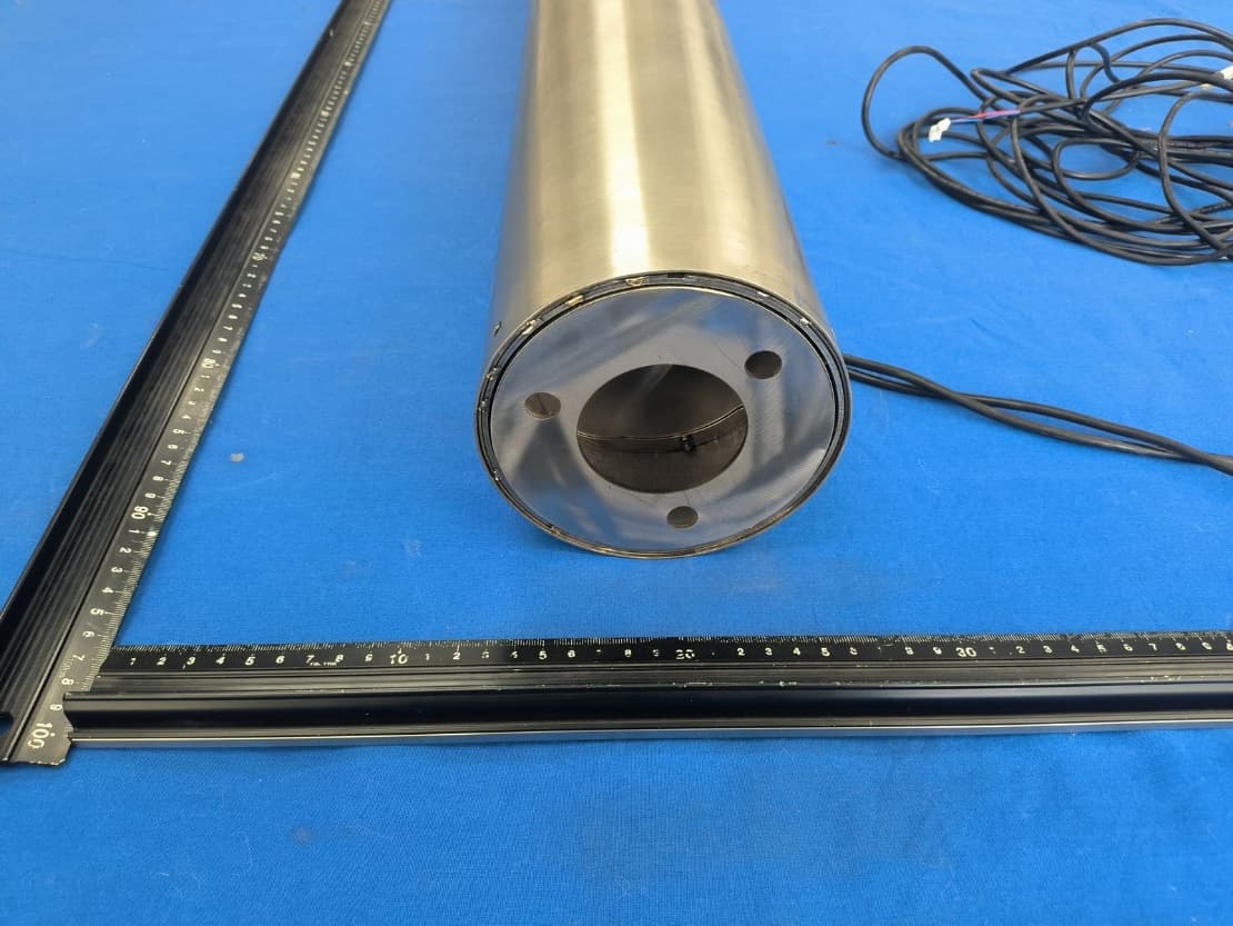
2ADTD-K7CRT01E
Nov 08, 2022Stand Pole
Equipment Class
DCD - Part 15 Low Power Transmitter Below 1705 kHz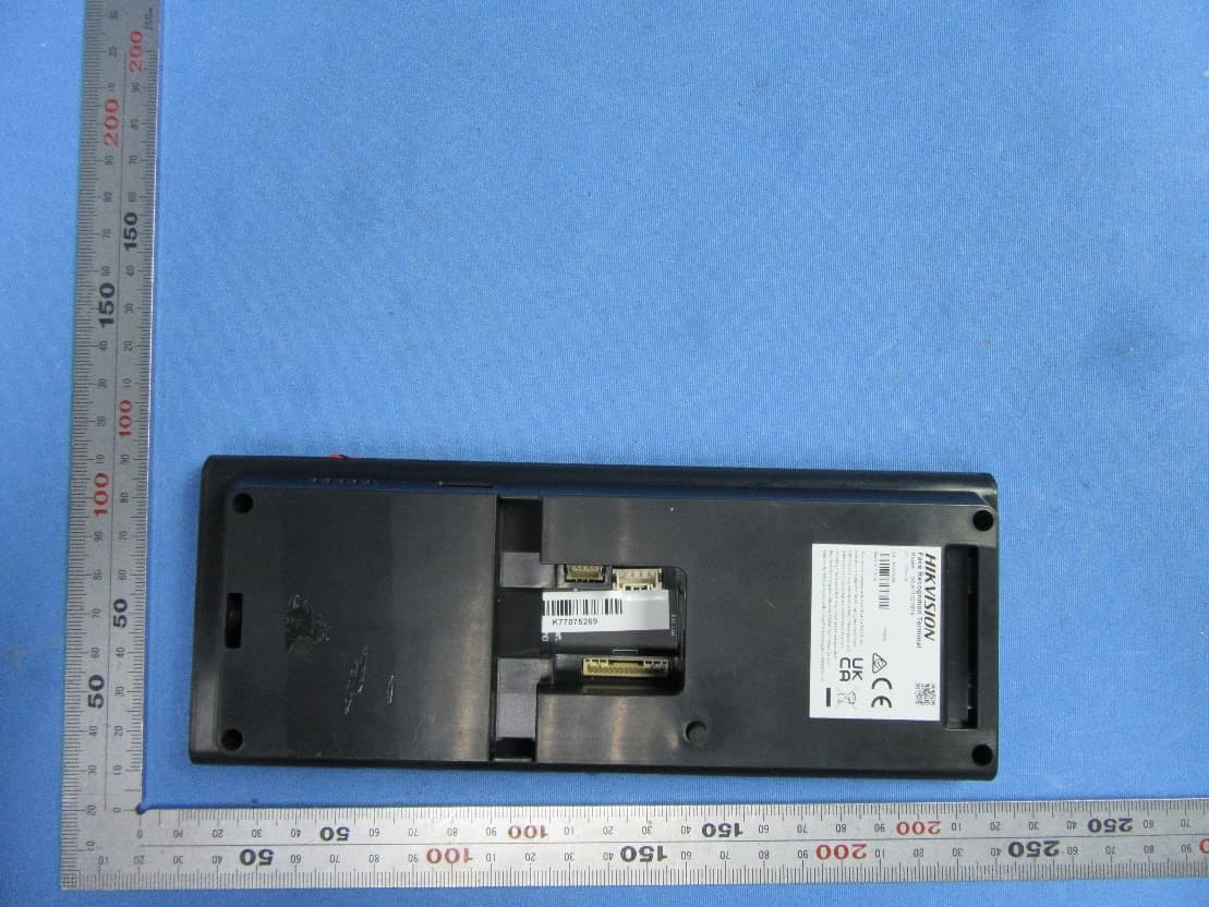
2ADTD-K1T321MFX
Nov 08, 2022Face Recognition Terminal
Equipment Class
DXX - Part 15 Low Power Communication Device Transmitter