2ADTK-SAT0001100FoobotSAT
Airboxlab S.A.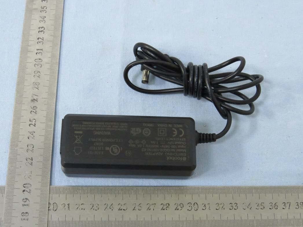
Click to zoom
Application Details
- Equipment Class
- DTS - Digital Transmission System
- Date of Grant
- Mar 23, 2021
- Application Purpose
- Original Equipment
- Date of Application
- Mar 23, 2021
- Equipment Note
- FoobotSAT
- Frequency Range
- 2402.00000000 - 2480.00000000
- Company
- Airboxlab S.A.
- Country
- Luxembourg
Documents & Files
Document Text
Text extracted from the exhibit documents filed with the FCC. Open a document above to read the original.
Users Manual
USER MANUAL Welcome 4 Items included 5 Getting to know your FoobotSAT 7 Optional Accessories FoobotSAT stand 19 DC Power supply 20 Installation Overview 8 Optimal device location 9 Securing the mounting plate 9 Items you will need 10 Drilling a path through for DC Jack & Ethernet cables 10 Securing the mounting plate 13 Wire connections 14 Power options 14 Internet connectivity options 14 Attaching the device to its mounting plate 14 Ceiling mounted 14 Wall mounted 17 Get the App and set up the device 18 Usage instructions Product Status 21 Consult or Retrieve FoobotSAT Readings 22 Factory reset 22 Intended Use 23 Environmental condition limits 23 Important safety instructions 24 Regulatory Information 26 ENGLISH FRANCAIS FoobotSAT monitors fine particulates, volatile organic compounds, carbon dioxide, temperature, relative humidity and features an infrared motion detection sensor. This user manual will provide basic guidance for set up, first use, and troubleshooting. Further information, tutorials, and troubleshooting guides can be found on https://foobot.io or by contacting your reseller. Welcome 5 ENGLISH FRANCAIS Items included FoobotSAT monitor User Manual Mounting plate U S E R M A N UA L Getting to know your FoobotSAT Status lights Motion sensor Setup button 7 ENGLISH FRANCAIS QR code for setup Reset button DC Power PoE enable Ethernet port Select the optimal de vice location. Secure the mounting plate to the wall or ceiling. Connect the DC c able to the device. Attach FoobotSAT to its mounting plate by rotating it. Get the App to set up the device and follow the instructions to have it connected to the Internet. 1 2 3 4 5 Each of these steps are detailled further detailed in the following pages. The installation of FoobotSAT should be completed by a qualified tech- nician, and all wiring used to install the device must be in accordance with your local jurisdiction’s codes. Permanent connection to the fixed wiring of the building should be made in a suitable junction box. Installation Ov erview 9 1.2m to 1.8m (4ft to 6ft) above floor depending if occupants are typically seated or standing. Minimum 1m (40in) from doors, windows and air outlets. ENGLISH FRANCAIS 1 Optimal device location Wall mount FoobotSAT can either be attached to a wall or ceiling. A third option is to use it with a stand — see the accessories section. Any other placement will result in unexpected behavior and is to be avoided. Ceiling mount Minimum 1m (40in) from doors, windows, walls and air outlets. Recommanded height 2.40m to 2.80m (8 to 9ft) 11 Items you will need A minimum of 4 screws from 4-48 to ¼-38 dimensions. (M3 to M5 dimensions). Head thickness of the screw should not exceed 3.3mm. Matching drywall plugs or anchors. Matching screwdriver. Drill bits matching your anchors or drywall plugs. Optional: Drill bits to let DC jack and Ethernet cable through. A B C D E Make sure you have the proper screws, anchors and the protection equipment required in your jurisdiction before getting started. 2 Securing the mounting plate ENGLISH FRANCAIS Drilling a path through for DC Jack & Ethernet cables You can use the canvas on the next page to help drill in a ceiling plate for the cables to go throug: • The bigger circle required for Ethernet is 0.9in (23mm) of diameter. • The smaller one is 0.5in (13mm) diameter for the DC jack. For the wall mounting option, use the glitter to secure the DC jack before screwing in the mounting plate. Use a minimum of 4 screws and associated drywall plug or anchor to secure the mounting plate to the wall or ceiling. Secure the mounting plate 13 ENGLISH FRANCAIS P ower options Internet c onnectivity options F oobotSAT can be powered via a 12 Volt DC power supply FoobotSAT can be either connected via a 2.4GHz WiFi connection or using a standard Ethernet (RJ45) cable. 2 Wir e connections 15 Ceiling mounted Once you have prepared the wiring and have the mounting plate attached to the ceiling you should connect the cable(s): ENGLISH FRANCAIS 3 Attach the device to its mounting plate Then hook the FoobotSAT to the mounting plate and rotate it clockwise 17 Wall mounted Connect the DC Jack to the device, then hook the FoobotSAT to its mounting plate and rotate it clockwise: Gently pull the DC cable while approaching the device to the mounting plate. Note that in this configuration, motion detection will not be accurate, and you have to make sure to locate the user button on the top right, so the monitoring sensors function properly. ENGLISH FRANCAIS Visit http://getapp.foobot.io from your tablet or smartphone to download the mobile app. Alternatively, use the setup app or method supplied by your reseller. Follow the instructions to get the monitor connected to the internet. 4 Get the App and set up the device 19 Optional accessories FoobotSAT stand FoobotSAT and Stand can be placed on a desk, table, or furniture. Make sure to have to the user button located on the top right, so the monito- ring sensors function properly. In this configuration motion detection will only cover a limited area. ENGLISH FRANCAIS DC Power supply UL compliant 12V Foobot power supply, delivering between 0.5 and 1.5 amps. 21 Product Status Use the following to understand product status, and troubleshoot: For more information and troubleshooting guides, check http://help.foobot.io Usage instructions Loop of 3 blue LEDs. lighting up, one after another Center LED blinking slowly in blue. Loop of 3 orange LEDs. lighting up, one after another SETUP OK DISCONNECTED The device is ready to be setup via the app. Monitor is running correctly and sends its readings to the internet platform. The device is not connected to the internet. ENGLISH FRANCAIS Once product set up is complete and the device is connected to the internet, visit http://dashboard.foobot.io from your computer or tablet. Alternatively, use the retrieval method or app supplied by your reseller. To perform a factory reset, you need to press the button at the …
Text truncated - open the document above for the full version.
Cover Letter(s)
C5266091_X8_Ed.1 1/1 Letter of Authorization Company: Airboxlab S.A. Address: 3 av du blues, 4368 Sanem, Luxembourg Product Name: FoobotSAT Model Number: SAT0001100 FCC Identifier: 2ADTK-SAT0001100 We authorize LGAI Technological Center S.A., Ronda de la Font del Carme, s/n, 08193 Bellaterra, Spain, to act on our behalf on all matters concerning the above named equipment. Any individual within LGAI Technological Center S.A. is authorized to act on our behalf and take action on the application. We declare that authorize LGAI Technological Center S.A., Ronda de la Font del Carme, s/n, 08193 Bellaterra, Spain, is allowed to forward all information related to the approval project to the Federal Communication Commission and to discuss any issues concerning the approval application. Any and all acts carried out by LGAI Technological Center S.A. on our behalf shall have the same effect as acts of our own. Name: Inouk Bourgon Date: 3/10/2021 Title: Chief technical officer Signature of applicant: Airboxlab S.A.
Cover Letter(s)
C5266091_X10_Ed.1 1/1 Airboxlab S.A. Office of Engineering Technology Federal Communications Commission 7435 Oakland Mills Road Columbia, MD 21046 Date: 2/25/2021 Subject: Request for Confidentiality FCC ID: 2ADTK-SAT0001100 To Whom It May Concern, Pursuant to the provisions of Sections 0.457 and 0.459 of Commission's rules (47CFR0.457, 0.459), we are requesting the Commission to withhold the following attachment(s) as confidential document from public disclosure. Exhibits Long-Term Confidentiality Short-Term Confidentiality ID Label/Location No No Attestation Statement No No External Photos No Block Diagram Schematics Test Report No No Test Setup Photos No User’s Manual Internal Photos Parts List / Tune Up RF Exposure Info Operational Description Cover Letter(s) No No SDR Software / Security Info No Above mentioned document contains detailed system and equipment description are considered as proprietary information in operation of the equipment. The public disclosure of above documents might be harmful to our company and would give competitor an unfair advantage in the market. It is our understanding that all measurement test reports, FCC ID label format and correspondent during certification review process cannot be granted as confidential documents and those information will be available for public review once the grant of equipment authorization is issued. Sincerely, Signature: Name: Inouk Bourgon Title: Chief technical officer
External Photos
FCC ID: 2ADTK-SAT0001100 IC: 26692-SAT0001100 External photo FCC ID: 2ADTK-SAT0001100 IC: 26692-SAT0001100 FCC ID: 2ADTK-SAT0001100 IC: 26692-SAT0001100 FCC ID: 2ADTK-SAT0001100 IC: 26692-SAT0001100 FCC ID: 2ADTK-SAT0001100 IC: 26692-SAT0001100 FCC ID: 2ADTK-SAT0001100 IC: 26692-SAT0001100 Adapter: GQ24-120150-E2 FCC ID: 2ADTK-SAT0001100 IC: 26692-SAT0001100 FCC ID: 2ADTK-SAT0001100 IC: 26692-SAT0001100 Adapter: SK03T1-1200150W2 FCC ID: 2ADTK-SAT0001100 IC: 26692-SAT0001100 FCC ID: 2ADTK-SAT0001100 IC: 26692-SAT0001100
ID Label/Location Info
1 A 2 3 4 5 678 12 3 4 5 678 B C D E F A B C D E F Title Scale Created by Size Sheet Rev Project Date Unit Louis Morandy_Rapiné 26-Nov-20 1/1 Label Size Foobot Sat 1/1 4 A3 mm 26.81 26.18
Internal Photos
FCC ID: 2ADTK-SAT0001100 IC: 26692-SAT0001100 Internal photo FCC ID: 2ADTK-SAT0001100 IC: 26692-SAT0001100 FCC ID: 2ADTK-SAT0001100 IC: 26692-SAT0001100 FCC ID: 2ADTK-SAT0001100 IC: 26692-SAT0001100 Adapter: GQ24-120150-E2 BT& WIFI Antenna BT & WIFI Chip FCC ID: 2ADTK-SAT0001100 IC: 26692-SAT0001100 FCC ID: 2ADTK-SAT0001100 IC: 26692-SAT0001100 Adapter: SK03T1-1200150W2 FCC ID: 2ADTK-SAT0001100 IC: 26692-SAT0001100 FCC ID: 2ADTK-SAT0001100 IC: 26692-SAT0001100
RF Exposure Info
Dongguan Nore Testing Center Co., Ltd. Report No.: NTC2007264F-1 FCC ID: 2ADTK-SAT0001100 RF EXPOSURE EVALUATION EUT Specification EUT FoobotSAT Frequency band (Operating) WLAN: 2.412GHz ~ 2.472GHz WLAN: 5.18GHz ~ 5.24GHz WLAN: 5.745GHz ~ 5825GHz Others(Bluetooth: 2.402GHz ~ 2.480GHz) Device category Portable (<20cm separation) Mobile (>20cm separation) Others ___ Antenna diversity Single antenna Multiple antennas Tx diversity Rx diversity Tx/Rx diversity Max. output power For WIFI: 15.51dBm(35.56mW) For BLE: 4.63dBm(2.90mW) Antenna gain 0 dBi Evaluation applied MPE Evaluation SAR Evaluation Limits for Maximum Permissible Exposure (MPE) Frequency Range(MHz) Electric Field Strength(V/m) Magnetic Field Strength(A/m) Power Density(mW/cm 2 ) 300-1500 -- -- F/1500 1500-100000 -- -- 1 Dongguan Nore Testing Center Co., Ltd. Report No.: NTC2007264F-1 FCC ID: 2ADTK-SAT0001100 Friis transmission formula: Pd=(Pout*G)\(4*pi*R 2 ) Where Pd= Power density in mW/cm 2 Pout=output power to antenna in Mw G= gain of antenna in linear scale Pi=3.1416 R= distance between observation point and center of the radiator in cm Pd the limit of MPE, 1mW/cm2. If we know the maximum gain of the antenna and total power input to the antenna, through the calculation, we will know the distance where the MPE limit is reached. Measurement Result Channel Gain Channel Frequency (MHz) Max Output power (dBm) Tolerance Max Tune-UP power (mW) Power density at 20cm (mW/ cm2 ) Power density Limits (mW/cm2 ) GFSK Low 0 2402 3.78 ± 0.5 2.68 5.33e-4 1 Middle 0 2440 4.63 ± 0.5 3.26 6.48e-4 1 High 0 2480 4.45 ± 0.5 3.13 6.22e-4 1 Dongguan Nore Testing Center Co., Ltd. Report No.: NTC2007264F-1 FCC ID: 2ADTK-SAT0001100 Note: Bluetooth and WIFI can be used at the same time. Power density at 20cm (mW/ cm2 ) Power density at 20cm (mW/ cm2 ) To t a l Power density at 20cm (mW/ cm2 ) Limits (mW/cm2 ) Test Result BLE WIFI BLE+WIFI 6.48e-4 0.0079 0.008548 1 Pass Channel Gain Channel Frequency (MHz) Max Output power (dBm) Tolerance Max Tune-UP power (mW) Power density at 20cm (mW/ cm2 ) Power density Limits (mW/cm2 ) 802.11b Low 0 2412 15.44 ± 0.5 39.26 0.0078 1 Middle 0 2437 15.37 ± 0.5 38.64 0.0078 1 High 0 2462 15.51 ± 0.5 39.90 0.0079 1 802.11g Low 0 2412 14.36 ± 0.5 30.62 0.0061 1 Middle 0 2437 14.40 ± 0.5 30.90 0.0061 1 High 0 2462 14.59 ± 0.5 32.28 0.0064 1 802.11n HT20 Low 0 2412 14.34 ± 0.5 30.48 0.0061 1 Middle 0 2437 14.32 ± 0.5 30.34 0.0060 1 High 0 2462 14.51 ± 0.5 31.70 0.0063 1 802.11n HT40 Low 0 2422 12.09 ± 0.5 18.16 0.0036 1 Middle 0 2437 12.11 ± 0.5 18.24 0.0036 1 High 0 2452 11.95 ± 0.5 17.58 0.0035 1
Test Report
Report No.: NTC2007264FV00 Page 2 of 57 Table of Contents 1. Summary of Test Result................................................................................................................................ ........ 4 2. General Description of EUT................................................................................................................................ .. 5 3. Test Channels and Modes Detail................................................................................................ .......................... 8 4. Configuration of EUT................................................................................................................................ ............. 8 5. Modification of EUT................................................................................................................................ ............... 9 6. Description of Support Device................................................................................................ ............................... 9 7. Test Facility and Location ................................................................................................................................... 10 8. Applicable Standards and References ................................................................................................................ 10 9. Deviations and Abnormalities from Standard Conditions ................................................................................... 11 10. Test Conditions ................................................................................................................................................. 11 11. Measurement Uncertainty ................................................................................................................................. 11 12. Sample Calculations ......................................................................................................................................... 12 13. Duty Cycle of Test Signal .................................................................................................................................. 12 14. Test Items and Results ..................................................................................................................................... 13 14.1 Conducted Emissions Measurement .......................................................................................................................................... 13 14.2 Maximum Conducted Output Power Measurement .................................................................................................................... 23 14.3 6dB Bandwidth Measurement .................................................................................................................................................... 25 14.4 Power Spectral Density Measurement ....................................................................................................................................... 30 14.5 Band Edge and Conducted Spurious Emissions Measurement ................................................................................................. 35 14.6 Radiated Spurious Emissions and Restricted Bands .................................................................................................................. 42 14.7 Antenna Requirement ................................................................................................................................................................. 56 15. Test Equipment List ........................................................................................................................................... 57 Report No.: NTC2007264FV00 Page 3 of 57 Revision History Report Number Description Issued Date NTC2007264FV00 Initial Issue 2021-03-11 Report No.: NTC2007264FV00 Page 4 of 57 1. Summary of Test Result FCC Rules Description of Test Result Remarks §15.207 (a) AC Power Conducted Emission PASS --- §15.247(b)(3) Maximum Conducted Output Power PASS --- §15.247(a)(2) 6dB Bandwidth PASS --- §15.247(e) Power Spectral Density PASS --- §15.247(d) Band Edge and Conducted Spurious Emissions PASS --- §15.247(d),§15.209, §15.205 Radiated Spurious Emissions and Restricted Bands PASS --- §15.203 Antenna Requirement PASS --- Report No.: NTC2007264FV00 Page 5 of 57 2. General Description of EUT Product Information Product Name: FoobotSAT Main Model Name: SAT0001100 Additional Model Name: N/A Model Difference: N/A S/N: 2007-2305 Brand Name: Foobot Hardware Version: V00 Software Version: V00 Rating: DC 12V come from Adapter Typical arrangement: Table-top I/O Port: DC Port*1, Ethernet Port*1 Accessories Information Adapter 1: M/N: SK03T1-1200150W2 Input: AC100-240V 50/60Hz, 0.6A Max Output: DC 12.0V 1.5A 18.0W Adapter 2: M/N: GQ24-120150-E2 Input: AC100-240V 50/60Hz, 1.0A Max Output: DC 12.0V 1.5A Cable: AC mains: 1.00m unshielded DC line: 1.51m unshielded Other: N/A Additional Information Note: N/A Remark: All the information above are provided by the manufacturer. More detailed feature of the EUT please refers to the user manual. Report No.: NTC2007264FV00 Page 6 of 57 Technical Specification (2.4GHz WLAN) Frequency Range: 2412-2472MHz for IEEE 802.11b/g/n(HT20) 2422-2462MHz for IEEE 802.11n(HT40) Modulation Technology: DSSS, OFDM Modulation Type: CCK, DQPSK, DBPSK, 64-QAM, 16-QAM, QPSK, BPSK Number of Channel: 13 for IEEE 802.11b/g/n(HT20) 9 for IEEE 802.11n(HT40) Channel Space: 5MHz Antenna Type: PCB antenna Antenna Gain: 0 dBi (Declared by manufacturer) Technical Specification (BLE) Frequency Range: 2402-2480MHz Modulation Type: GFSK Number of Channel: 40 Channel Space: 2MHz Antenna Type: PCB antenna Antenna Gain: 0 dBi (Declared by manufacturer) Report No.: NTC2007264FV00 Page 7 of 57 Channel List IEEE 802.11b/ g/ n(HT20) IEEE 802.11 n(HT40) Channel Frequency (MHz) Channel Frequency (MHz) 1 2412 --- --- 2 2417 --- --- 3 2422 3 2422 4 2427 4 2427…
Text truncated - open the document above for the full version.
Test Setup Photos
FCC ID: 2ADTK-SAT0001100 IC: 26692-SAT0001100 Test photo Radiated emission Below 30MHz 30MHz-1GHz FCC ID: 2ADTK-SAT0001100 IC: 26692-SAT0001100 Above 1GHz Conducted emission
Contact Information
Applicant
Inouk Bourgon(Chief technical officer)
Technical Contact
Non-Technical Contact
Dongguan NTC Co., Ltd.Jees hong
[email protected]86-0769-22022444
Test Firm
Dongguan NTC CO., Ltd.Jees Hong
[email protected]+86-769-22022444
Technical Specifications
| # | Rule Parts | Frequency Range | Power Output |
|---|---|---|---|
| 2 | 15C | 2.40 GHz - 2.48 GHz | 2.90 mW |
Other Applications from Airboxlab S.A.
2ADTK-FBT0002100
Jul 26, 2015Indoor Air Quality Sensor
Equipment Class
DTS - Digital Transmission System