2ADXC-LKV488MINIRHDMI Wireless Extender
Shenzhen Lenkeng Technology Co., Ltd
Click to zoom
Application Details
- Equipment Class
- NII - Unlicensed National Information Infrastructure TX
- Date of Grant
- Nov 07, 2023
- Application Purpose
- Original Equipment
- Date of Application
- Nov 07, 2023
- Equipment Note
- HDMI Wireless Extender
- Frequency Range
- 5180.00000000 - 5240.00000000
- Country
- China
Documents & Files
Document Text
Text extracted from the exhibit documents filed with the FCC. Open a document above to read the original.
Users Manual
User Manual 4K 60Hz HDMI Wireless Extender The product name and brand name may be registered trademark of related manufacturers. ™ and ® may be omitted on the user manual. The pictures on the user manual are just for reference, The terms HDMI, HDMI High-Definition Multimedia Interface, and the HDMI Logo are trademarks or registered trademarks of HDMI Licensing Administrator, Inc. We reserve the rights to make changes without further notice to a product or system described herein to improve reliability, function or design. Disclaimer · Important Safety Instructions · Introduction This is a 4K@60Hz HDMI wireless extender, including a transmitter and a receiver. Adopting ipcolor STREAM technology can realize high definition and low-latency transmission. Based on the 5G wireless frequency band, with stable anti-interference and safety performance. It supports 1-to-1 wireless transmission, and the transmission distance can reach 20 meters, effectively solving problems caused by complicated wiring. It's an ideal wireless video transmission solution for video conferences, home entertainment, multimedia education, etc. Note: 1) Transmission distances may vary depending on the environment. 2) Signals may be reduced or completely lost by solid structures such as walls, bricks, and glass. 3) The surrounding wireless signal may cause certain interference to the transmission, and the channel can be switched to reduce the interference. 1) Do not expose this device to rain or place it near water. Any liquid that goes into the device may cause a failure, fire, or electric shock. 2) Never insert anything metallic into the open parts of this device. This may cause a danger of electric shock. 3) The device should be repaired only by a qualified technician. 4) Do not place this device near or over a radiator or heat register, or where it is exposed to direct sunlight. 2 · Features 1. Adopting ipcolor STREAM technology can realize high definition and low-latency transmission. 2. Support up to 3840x2160@60Hz resolution, backward compatible. 3. Support wireless transmission up to 20 meters (line of sight). 4. In case of multiple sets of products in the same area, support SSID pairing and channel switching to avoid interference. 5. Support 5G wireless frequency bands, strong anti-interference. 6. Support firmware upgrade via Micro USB port. 7. Portable design, plug and play. 43 · Installation Requirements 1. HDMI source device (DVD, game console, PC, etc.) 2. HDMI display device (TV, projector, LED screen, etc.) Transmitter x1 Receiver x1Micro USB cable x2 · Package Contents User manual x1 · Panel Description Transmitter (TX) ① ② WiFi indicator HDMI inputConnect with HDMI source device ⑥ Micro USB portFor power input and firmware upgrade a) Slow flash: waiting for connection b) Steady on: connection succeeded c) Quick flash: SSID Pairing mode ④ Channel switch button a) press to switch channels b) Press and hold 5s for SSID pairing c) Press and hold 10s for restore factory settings ⑤ Signal indicator a) Light off: no HDMI signal b) Steady on: HDMI signal is transmitting c) Quick flash: restore factory settings ③ Power indicator The indicator will turn red when the power is turned on ① ② ③ ④ ⑤ ⑥ Receiver (RX) 5 ① ② WiFi indicator HDMI outputConnect with HDMI display device ⑥ Micro USB portFor power input and firmware upgrade a) Slow flash: waiting for connection b) Steady on: connection succeeded c) Quick flash: SSID Pairing mode ④ Channel switch button a) After connecting with TX, press to switch channels b) Press and hold 5s for SSID pairing c) Press and hold 10s for restore factory settings ⑤ Signal indicator a) Light off: no HDMI signal b) Steady on: HDMI signal is transmitting c) Quick flash: restore factory settings ③ Power indicator The indicator will turn red when the power is turned on ① ② ③ ④ ⑤ ⑥ 1. Connection Diagrams 2. Connection Instructions a) Connect the transmitter to the HDMI output port of the signal source device. b) Connect the receiver to the HDMI input port of the display device. c) Plug the power supply into the devices to get started. 3. SSID Pairing 1. Enter the SSID pairing mode by holding the transmitter and receiver's channel switch buttons for five seconds. Both WiFi connection indicators will flash quickly in blue. Note: Please connect the Micro USB cable to the 5V 1A wall charger when transmitting 4K video, for long-distance use or when the picture is not smooth. One to one connection 6 Transmitter Receiver · Installation Procedures HDMI Display Macbook · FAQ Q: Why the receiver and transmitter cannot be connected, showing "Search ipcolor Tx..." on the screen? A: 1) Move transmitter and receiver closer. 2) Re-power the transmitter or receiver. 3) Re-pair the transmitter and receiver. Q: Why the Wi-Fi indicator is steady on but showing "Please check the TX input signal" ? A: 1) Make sure the TX has HDMI input and that the resolution is within the specified range. 2) Try to connect the signal source directly to the display device, or change the signal source and HDMI cable and test again. 7 8 2. When the SSID pairing is successful, the WiFi indicators on the transmitter and receiver will change from quick flashing to slow flashing or steady on. · Specification Power Supply HDMI Performance and Interface Transmission Micro USB power supply (5V/1A)Voltage/Current Power consumptionTX < 4.5W, RX < 3.5W HDMI versionHDMI 2.0 HDCP versionHDCP 1.4/HDCP 2.2 Max transmission rate 18Gbps Resolution supported 3840x2160@24/30/50/60Hz (YUV 4:4:4, YUV 4:2:2 and RGB),1080P@50/60Hz, 720P@50/60Hz, 1920x1200@60Hz Input and output TMDS signal 0.7~1.2Vp-p(TMDS) Input and output DDC signal 5Vp-p(TTL) Wi-Fi Frequency bands 5.18-5.24 GHz Transmission distance ≤ 20m ItemsSpecifications Q: Why is the display stuttering or unstable? A: 1) Place the transmitter or receiver within the signal coverage and minimize obstructions between the transmitter and receiver. 2) Switch to a different channel to avoid interfe…
Text truncated - open the document above for the full version.
External Photos
Reference No.: WTH23X08185692W001 Page 2 of 13 Waltek Testing Group (Shenzhen) Co., Ltd. Http://www.waltek.com.cn EXHIBIT 2 - EUT EXTERNAL PHOTOGRAPHS EUT View 1 EUT View 2 Reference No.: WTH23X08185692W001 Page 3 of 13 Waltek Testing Group (Shenzhen) Co., Ltd. Http://www.waltek.com.cn EUT View 3 EUT View 4 Reference No.: WTH23X08185692W001 Page 4 of 13 Waltek Testing Group (Shenzhen) Co., Ltd. Http://www.waltek.com.cn EUT View 5 EUT View 6 Reference No.: WTH23X08185692W001 Page 5 of 13 Waltek Testing Group (Shenzhen) Co., Ltd. Http://www.waltek.com.cn EUT View 7
ID Label/Location Info
Reference No.: WTH23X08185692W001 Page 1 of 13 Waltek Testing Group (Shenzhen) Co., Ltd. Http://www.waltek.com.cn ANNEX EXHIBIT 1 - PRODUCT LABELING Proposed FCC ID Label Format FCC ID: 2ADXC-LKV488MINIR Specifications: The label shall be securely affixed to a permanently attached part of the device, in a location where it is visible or easily accessible to the user, and shall not be readily detachable. The label shall be sufficiently durable to remain fully legible and intact on the device in all normal conditions of use throughout the device’s expected lifetime. Proposed Label Location on EUT FCC ID Label Location
Internal Photos
Reference No.: WTH23X08185692W001 Page 6 of 13 Waltek Testing Group (Shenzhen) Co., Ltd. Http://www.waltek.com.cn EXHIBIT 3 - EUT INTERNAL PHOTOGRAPHS EUT Housing and Board View 1 Solder Board-Component View 1 Reference No.: WTH23X08185692W001 Page 7 of 13 Waltek Testing Group (Shenzhen) Co., Ltd. Http://www.waltek.com.cn Solder Board-Component View 2 Solder Board-Component View 3 Reference No.: WTH23X08185692W001 Page 8 of 13 Waltek Testing Group (Shenzhen) Co., Ltd. Http://www.waltek.com.cn Solder Board-Component View 4 Solder Board-Component View 5 Reference No.: WTH23X08185692W001 Page 9 of 13 Waltek Testing Group (Shenzhen) Co., Ltd. Http://www.waltek.com.cn Solder Board-Component View 6 Solder Board-Component View 7 Reference No.: WTH23X08185692W001 Page 10 of 13 Waltek Testing Group (Shenzhen) Co., Ltd. Http://www.waltek.com.cn Solder Board-Component View 8 Antenna View WIFI 1 Antenna WIFI 0 Antenna
RF Exposure Info
1. RF Exposure Requirements 1.1 General Information Client Information Applicant: Shenzhen Lenkeng Technology Co.,Ltd Address of applicant: West 4F,Jinguangxia Culture&Tech Park, 3 Guangxia Road, Shenzhen, China Manufacturer: Shenzhen Lenkeng Technology Co.,Ltd Address of manufacturer: West 4F,Jinguangxia Culture&Tech Park, 3 Guangxia Road, Shenzhen, China General Description of EUT: Product Name: HDMI Wireless Extender Trade Name: LENKENG Model No.: LKV488Mini-RX Adding Model(s): / Rated Voltage: DC5V Battery Capacity: / Power Adapter: / FCC ID: 2ADXC-LKV488MINIR Equipment Type: Mobile device Technical Characteristics of EUT: Support Standards: 802.11a, 802.11n-HT20 , 802.11n-HT40, 802.11ac-VHT20, 802.11ac-VHT40,802.11ac-VHT80 Frequency Range: 5150-5250MHz RF Output Power: Antenna 0: 15.91dBm (Conducted) Antenna 1: 15.86dBm (Conducted) Type of Modulation: QPSK, 16QAM, 64QAM,256QAM Type of Antenna: FPC Antenna Antenna Gain: Antenna 0:1.76dBi Antenna 1: 2.86dBi 1.2 RF Exposure Exemption According to §1.1307(b)(3) and KDB 447498 D04 Interim General RF Exposure Guidance v01, system operating under the provisions of this section shall be operating in a manner that the public is not exposed to radio frequency energy level in excess limit for maximum permissible exposure. Option A: FCC Rule Part 1.1307 (b)(3)(i)(A):The available maximum time-averaged power is no more than 1mW, regardless of separation distance. Option B: FCC Rule Part 1.1307 (b)(3)(i)(B): The available maximum time-averaged power or effective radiated power (ERP), whichever is greater, is less than or equal to the threshold P th (mW) described in the following formula. P th is given by: Option C: FCC Rule Part 1.1307 (b)(3)(i)(C): The minimum separation distance (R in meters) from the body of a nearby person for the frequency (f in MHz) at which the source operates, the ERP (watts) is no more than the calculated value prescribed for that frequency. R must be at least λ/2π, where λ is the free-space operating wavelength in meters. Single RF Sources Subject to Routine Environmental Evaluation RF Source frequency (MHz) Threshold ERP (watts) 0.3-1.34 1,920 R 2 1.34-30 3,450 R 2 /f 2 30-300 3.83 R 2 300-1,500 0.0128 R 2 f 1,500-100,000 19.2R 2 For Multiple RF sources: FCC Rule Part 1.1307(b)(3)(ii): (A) The available maximum time-averaged power of each source is no more than 1 mW and there is a separation distance of two centimeters between any portion of a radiating structure operating and the nearest portion of any other radiating structure in the same device, except if the sum of multiple sources is less than 1 mW during the time-averaging period, in which case they may be treated as a single source (separation is not required). (B) In the case of fixed RF sources operating in the same time-averaging period, or of multiple mobile or portable RF sources within a device operating in the same time averaging period, if the sum of the fractional contributions to the applicable thresholds is less than or equal to 1 as indicated in the following equation. 1.3 Calculated Result Radio Access Technology Prediction Frequency Output Power Antenna Gain Duty Cycle Tune-Up Time-Averaged Power ERP (MHz) (dBm) (dBi) (%) (dBm) (dBm) Wi-Fi Antenna 0 5180 15.91 1.76 100 16.00 15.61 Wi-Fi Antenna 1 5180 15.86 2.86 100 16.00 16.71 Frequency Option Min. Distance Max. Power Exposure Limit Ratio Result (MHz) (cm) (dBm) (mW) (mW) Pass/Fail 5180 C 20.00 15.61 36.39 768.00 0.05 Pass 5180 C 20.00 16.71 46.88 768.00 0.06 Pass Note: 1. Time-Averaged Power=Output Power * Duty Cycle; ERP= Time-Averaged Power+ Antenna gain-2.15dB 2. Option A, B and C refers as clause 1.2. 3. For option B, Max (time-averaged power, effective radiated power (ERP)) converts to Max. Power. For option C, ERP converts to Max. Power; 4. For option B, P th (mW) converts to Exposure Limit (mW); For option C, ERP (W) converts to Exposure Limit (mW). 5. Ratio= Tune-Up ERP (mW)/ Exposure Limit (mW) Mode for Simultaneous Multi-band Transmission: Radio Access Technology Ratio 1 Ratio 2 Simultaneous Ratio Limit Result Pass/Fail Wi-Fi Antenna 0&1 0.05 0.06 0.11 1 Pass Result: Pass
Test Report
ShenzhenTopolinkTechnologyCO.,Ltd 2023-10-1717:44:51 1 AcknowledgmentLetter SPECIFICATIONFORAPPROVAL CustomerName CUSTOMERNAME:Langqiang productname PRODUCTNAME:WIFIdualantennaANT0second-generationterminal linelength40MM Customerpartnumber CUSTOMERP/N: MANUFACTURER SIGNATURE CUSTOMER SIGNATURE CHECKEDBY:YanPeihao APPROVEDBY:FengJuan DATE:2023.2.3 Address:Room401-407,BuildingA,JinfulaiBuilding,DabaoRoad,District28,Bao'anDistrict, Shenzhen Phone:0755-27728733 Fax:0755-27805416 ShenzhenTopolinkTechnologyCO.,Ltd 2023-10-1717:44:51 2 Contents ItemDescription 1.............................................................Testinginstrumentsandenvironment 2.............................................................................................Matchingcircuit 3............................................................................Machineandantennapictures 4.....................................................................................S11circlediagram 5.................................................AntennaPassivePerformance – 3DTotalGainPattern 6.................................................AntennaPassivePerformance – 2DTotalGainPattern 7........................................................................................efficiencygain 8.....................................................................................Linesamplediagram ShenzhenTopolinkTechnologyCO.,Ltd 2023-10-1717:44:51 3 1.Testinstrumentandenvironment:CTIA743darkroom, 8960/5515C,withthephoneplacedbackwardsataturntable4 metersawayfromthestandardhornantenna 2、matchingcircuit Nomatchingcircuitadded。 matchingcircuitABC numericalvalueNF0ohmNF ShenzhenTopolinkTechnologyCO.,Ltd 2023-10-1717:44:51 4 3.Machineantennaimage: 4.AntennaANT0S11,ReturnLoss,Smithcirculardiagram: antennaANT0 antennaANT1 ShenzhenTopolinkTechnologyCO.,Ltd 2023-10-1717:44:51 5 5.AntennaPassivePerformance–3DTotalGainPattern 6.AntennaPassivePerformance–2DTotalGainPattern ShenzhenTopolinkTechnologyCO.,Ltd 2023-10-1717:44:51 6 7.AntennaANT0efficiencygain : ShenzhenTopolinkTechnologyCO.,Ltd 2023-10-1717:44:51 7 8.Lineplot 9.
Test Report
ShenzhenTopolinkTechnologyCO.,Ltd 2023-10-1717:45:24 1 AcknowledgmentLetter SPECIFICATIONFORAPPROVAL CUSTOMERNAME:Langqiang productname PRODUCTNAME:WIFIdualantennaANT1second-generationterminal linelength40MM Customerpartnumber CUSTOMERP/N: MANUFACTURER SIGNATURE CUSTOMER SIGNATURE CHECKEDBY:YanPeihao APPROVEDBY:FengJuan DATE:2023.2.3 Address:Room401-407,BuildingA,JinfulaiBuilding,DabaoRoad,District28,Bao'anDistrict, Shenzhen Phone:0755-27728733 Fax:0755-27805416 ShenzhenTopolinkTechnologyCO.,Ltd 2023-10-1717:45:24 2 Contents ItemDescription 1.............................................................Testinginstrumentsandenvironment 2.....................................................................................matchingcircuit 3............................................................................Machineandantennapictures 4..........................................................................................S11circlediagram 5..............................................AntennaPassivePerformance – 3DTotalGainPattern 6..............................................AntennaPassivePerformance – 2DTotalGainPattern 7.........................................................................................Efficiencygain 8.....................................................................................Linesamplediagram ShenzhenTopolinkTechnologyCO.,Ltd 2023-10-1717:45:24 3 1.Testinstrumentandenvironment:CTIA743darkroom, 8960/5515C,withthephoneplacedbackwardsataturntable4 metersawayfromthestandardhornantenna 2、matchingcircuit Nomatchingcircuitadded. matchingcircuitABC numericalvalueNF0ohmNF ShenzhenTopolinkTechnologyCO.,Ltd 2023-10-1717:45:24 4 3.Machineantennaimage: 4.AntennaANT1S11,ReturnLoss,Smithcirculardiagram: AntennaANT0 AntennaANT1 ShenzhenTopolinkTechnologyCO.,Ltd 2023-10-1717:45:24 5 5.AntennaPassivePerformance – 3DTotalGainPattern 6.AntennaPassivePerformance – 2DTotalGainPattern ShenzhenTopolinkTechnologyCO.,Ltd 2023-10-1717:45:24 6 7.AntennaANT1efficiencygain : ShenzhenTopolinkTechnologyCO.,Ltd 2023-10-1717:45:24 7 8.Lineplot
Test Report
Waltek Testing Group (Shenzhen) Co., Ltd. Http://www.waltek.com.cn Page 1 of 104 TEST REPORT Reference No. ................... .: WTH23X08185692W001 FCC ID ............................... .: 2ADXC-LKV488MINIR Applicant .......................... .: Shenzhen Lenkeng Technology Co.,Ltd Address ............................ .: West 4F,Jinguangxia Culture&Tech Park, 3 Guangxia Road, Shenzhen , China Manufacturer .................... .: The same as Applicant Address ............................ .: The same as Applicant Product Name .................. .: HDMI Wireless Extender Model No. .......................... .: LKV488Mini-RX Standards ......................... .: FCC Part 15.407 Date of Receipt sample ... .: 2023-08-24 Date of Test....................... .: 2023-08-24 to 2023-10-09 Date of Issue .................... .: 2023-10-09 Test Report Form No. ...... . : WTX_Part 15_407W Test Result ........................ .: Pass Remarks: The results shown in this test report refer only to the sample(s) tested, this test report cannot be reproduced, except in full, without prior written permission of the company. The report would be invalid without specific stamp of test institute and the signatures of approver. Prepared By: Waltek Testing Group (Shenzhen) Co., Ltd. Address: 1/F., Room 101, Building 1, Hongwei Industrial Park, Liuxian 2nd Road, Block 70 Bao'an District, Shenzhen, Guangdong, China Tel.: +86-755-33663308 Fax.: +86-755-33663309 Email: [email protected] Tested by: Approved by: Dashan Chen Silin Chen Reference No.: WTH23X08185692W001 Waltek Testing Group (Shenzhen) Co., Ltd. Http://www.waltek.com.cn Page 2 of 104 TABLE OF CONTENTS 1. GENERAL INFORMATION ................................................................................................................................... 5 1.1 PRODUCT DESCRIPTION FOR EQUIPMENT UNDER TEST (EUT) ............................................................................... 5 1.2 TEST STANDARDS ................................................................................................................................................... 6 1.3 TEST METHODOLOGY ............................................................................................................................................. 6 1.4 TABLE FOR PARAMETERS OF TEST SOFTWARE SETTING ......................................................................................... 6 1.5 EUT OPERATING DURING TEST .............................................................................................................................. 8 1.6 TEST FACILITY ....................................................................................................................................................... 8 1.7 EUT SETUP AND TEST MODE ................................................................................................................................. 9 1.8 MEASUREMENT UNCERTAINTY ............................................................................................................................ 10 1.9 TEST EQUIPMENT LIST AND DETAILS ................................................................................................................... 11 2. SUMMARY OF TEST RESULTS ......................................................................................................................... 14 3. ANTENNA REQUIREMENT ................................................................................................................................ 15 3.1 STANDARD APPLICABLE ....................................................................................................................................... 15 3.2 EVALUATION INFORMATION ................................................................................................................................ 15 4. AUTOMATICALLY DISCONTINUE TRANSMISSION .................................................................................. 16 4.1 STANDARD APPLICABLE ....................................................................................................................................... 16 4.2 SUMMARY OF TEST RESULTS ............................................................................................................................... 16 5. POWER SPECTRAL DENSITY ........................................................................................................................... 17 5.1 STANDARD APPLICABLE ....................................................................................................................................... 17 5.2 TEST PROCEDURE ................................................................................................................................................. 17 5.3 SUMMARY OF TEST RESULTS/PLOTS .................................................................................................................... 18 6. EMISSION BANDWIDTH AND OCCUPIED BANDWIDTH ........................................................................... 19 6.1 STANDARD APPLICABLE ....................................................................................................................................... 19 6.2 TEST PROCEDURE ................................................................................................................................................. 19 6.3 SUMMARY OF TEST RESULTS/PLOTS .................................................................................................................... 21 7. MAXIMUM CONDUCTED OUTPUT POWER .................................................................................................. 22 7.1 STANDARD APPLICABLE ....................................................................................................................................... 22 7.2 TEST PROCEDURE ...........................................................................................................................…
Text truncated - open the document above for the full version.
Test Setup Photos
Reference No.: WTH23X08185692W001 Page 11 of 13 Waltek Testing Group (Shenzhen) Co., Ltd. Http://www.waltek.com.cn EXHIBIT 4 - TEST SETUP PHOTOGRAPHS Conducted Emission Test Setup Radiation Emission Test Setup (Below 30MHz) Reference No.: WTH23X08185692W001 Page 12 of 13 Waltek Testing Group (Shenzhen) Co., Ltd. Http://www.waltek.com.cn Radiation Emission Test Setup (30MHz to 1GHz) Radiation Emission Test Setup (1GHz to 18GHz) Reference No.: WTH23X08185692W001 Page 13 of 13 Waltek Testing Group (Shenzhen) Co., Ltd. Http://www.waltek.com.cn Radiation Emission Test Setup (Above 18GHz) ***** END OF REPORT *****
Contact Information
Applicant
Luo yuqun(Manager)
Test Firm
Waltek Testing Group (Shenzhen) Co., Ltd.Jandy So
Technical Specifications
| # | Rule Parts | Frequency Range | Power Output |
|---|---|---|---|
| 1 | 15E | 5.18 GHz - 5.24 GHz | 58.30 mW |
Other Applications from Shenzhen Lenkeng Technology Co., Ltd
2ADXC-QBZ339RX
Jan 22, 2026HDMI Wireless Extender
Equipment Class
NII - Unlicensed National Information Infrastructure TX
2ADXC20WMD3AA
Mar 24, 2020wireless extender (WIFI)
Equipment Class
NII - Unlicensed National Information Infrastructure TX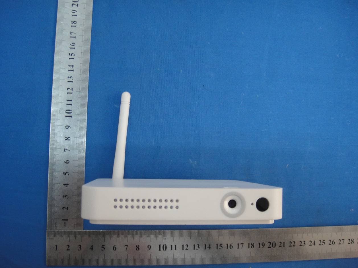
2ADXCEZTV3
Jan 11, 2015Android TV Box
Equipment Class
DTS - Digital Transmission System