2ADXW-RCL00Remote Control
SHENZHEN YIRUI ELECTRONIC TECHNOLOGY CO., LTD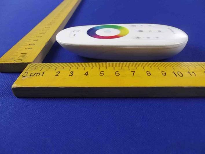
Click to zoom
Application Details
- Equipment Class
- DXX - Part 15 Low Power Communication Device Transmitter
- Date of Grant
- Feb 02, 2015
- Application Purpose
- Original Equipment
- Date of Application
- Feb 02, 2015
- Equipment Note
- Remote Control
- Frequency Range
- 2402.00000000 - 2480.00000000
- Country
- China
Documents & Files
Document Text
Text extracted from the exhibit documents filed with the FCC. Open a document above to read the original.
Users Manual
RGBW Remote Contro l User Instruction Thanks for your purchase ! the remotes can control the intensity 、 change the color and mode that is controlled by the programs、and you can master the speed of the lights flashing in each groups. Basic control functions Tips .Touch the color ring,you can get any color. .you can change the mode to get the individual color by the built-in program Program: 1.Red 2.Green 3.Blue 4.Yellow 5.Orange 6.Cyan 7.White 8.Red and Green 9.Red and Blue 10.Green and Bule 11.Red and Green and Blue 12.Red and Green and Blue and Yellow and Purple and Pink and White In this manual, you will learn about: > Basic functions of the remote controls: Ver1.0 We recommend using rechargeable batteries for the remote controls. For that reason, we don’t include ordinary batteries. We hope you appreciate our environmental friendly choices and they do not cause you any inconvenience. FCC STATEMENT : This device complies with Part 15 of the FCC Rules. Operation is subject to the following two conditions: (1) This device may not cause harmful interference, and (2) This device must accept any interference received, including interference that may cause undesired operation. Warning: Changes or modifications not expressly approved by the party responsible for compliance could void the user's authority to operate the equipment. NOTE: This equipment has been tested and found to comply with the limits for a Class B digital device, pursuant to Part 15 of the FCC Rules. These limits are designed to provide reasonable protection against harmful interference in a residential installation. This equipment generates uses and can radiate radio frequency energy and, if not installed and used in accordance with the instructions, may cause harmful interference to radio communications. However, there is no guarantee that interference will not occur in a particular installation. If this equipment does cause harmful interference to radio or television reception, which can be determined by turning the equipment off and on, the user is encouraged to try to correct the interference by one or more of the following measures: Reorient or relocate the receiving antenna. Increase the separation between the equipment and receiver. Connect the equipment into an outlet on a circuit different from that to which the receiver is connected. Consult the dealer or an experienced radio/TV technician for help. RF warning statement: The device has been evaluated to meet general RF exposure requirement. The device can be used in portable exposure condition without restriction.
Cover Letter(s)
SHENZHEN YIRUI ELECTRONIC TECHNOLOGY CO., LTD FCC Confidentiality Request Number:CF303 Version:V05 Date: 21-05-2012 (Permanent or also called long term confidentiality is the normal method to keep certain docuements confidential, and may apply to schematics, block diagrams, operational description and bill of materials.) To: Federal Communications Commission Equipment Authorization Branch 7435 Oakland Mills Road Columbia, MD 21046 Pursuant to 47 CFR Section 0.459(a) & (b), we, (the applicant / grantee) Company nameSHENZHEN YIRUI ELECTRONIC TECHNOLOGY CO., LTD AddressF4,Build B,SaiLian Industry Park,The 4th Industry Zone,Shuitian,Shiyan Town,Baoan District, CityShenzhen CountryChina request for this certification filing under: Grantee CodeProduct Number FCC ID:2ADXW-RCL00 to maintainpermanent confidentialityfor the following documents submitted within this application: (please cross what is applicable, or add other documents, provide the file name and description) ExhibitFile NameDescription √ Operational DescriptionOperational Descriptionexplaining the functioning of the block diagram √ Block DiagramsBlock Diagramsshowing the systematic building blocks of the EUT √ Schematics DiagramsSchematicsshowing components, their values and interconnection Bill of MaterialsList of components used on the PCB’s of the EUT Above materials crossed contain secrets, proprietary and technical information, which would customarily be guarded from competitors under 47 CFR, section 0.457(d)(2). Disclosure or publication or any portion of this company confidential material to other parties could cause substantial competitive harm and provide unjustified benefits for competitors. We understand that pursuant to 47 CFR section 0.457(d)(1)(ii) disclosure of the applicant and all accompanying documentation will not be made before the date of the grant. The documents indicated as confidential above, are not publicly available elsewhere. Attestation: City and Country:Date:Name: (this must be a person) Function:Signature: (or official company stamp) Shenzhen, China2015-01-21Fei YuElectronics Engineer
Cover Letter(s)
SHENZHEN YIRUI ELECTRONIC TECHNOLOGY CO., LTD FCC Authorization Letter Number:CF304 Version:V03 Date: 01-08-2011 We, (the approval holder) Company nameSHENZHEN YIRUI ELECTRONIC TECHNOLOGY CO., LTD AddressF4,Build B,SaiLian Industry Park,The 4th Industry Zone,Shuitian,Shiyan Town,Baoan District, CityShenzhen, CountryChina declare that the following representative (agent): Name (person)Tom Chen Company nameShenzhen Anbotek Compliance Laboratory Limited Addresss1/F., Building 1, SEC Industrial Park, No.0409 Qianhai Road, Nanshan District, CityShenzhen CountryChina is hereby authorized to apply the following equipment for certification on our behalf: Product DescriptionRemote Control Type or Model(s)L00-000001-00 Tradename or Brand(s)TOUCH LIGHT We also authorize Teleconformity (Mr. M. Koop, Manager Certification, Address: Rietven 31, 7534NH Enschede, the Netherlands) to apply and sign this application for certification, registration or filing on our behalf (as representative agent or certifier). Attestation: City and Country:Date:Name: (this must be a person) Function:Signature: (or official company stamp) Shezhen, China2015-01-21Fei YuElectronics Engineer
External Photos
Figure 1 The EUT-Top View Figure 2 The EUT-Bottom View Figure 3 The EUT-Front View Figure 4 The EUT-Back View Figure 5 The EUT-Right View Figure 6 The EUT-Left View
ID Label/Location Info
Label Location On EUT
ID Label/Location Info
Product Name: Remote Control Model No.: L00-000001-00 FCC ID: 2ADXW-RCL00
Internal Photos
Figure 7 The EUT-Inside View Figure 8 PCB of the EUT-Front View Figure 9 PCB of the EUT-Back View Figure 10 PCB of the EUT-Module View
Test Report
Shenzhen Anbotek Compliance Laboratory Limited FCC ID: 2ADXW-RCL00 Page 1 of 24 Report No.: R011410500E Shenzhen Anbotek Compliance Laboratory Limited Tel:(86)755-26066544 Fax:(86)755-26014772 www.anbotek.com FCC TEST REPORT for SHENZHEN YIRUI ELECTRONIC TECHNOLOGY CO., LTD Remote Control Model No.: L00-000001-00 Report Number:R011410500E Date of Test:Nov. 05~Dec. 19, 2014 Date of Report:Jan. 22, 2015 Prepared fo r:SHENZHEN YIRUI ELECTRONIC TECHNOLOGY CO., LTD Address:F4,Build B,SaiLian Industry Park,The 4th Industry Zone,Shuitian,Shiyan Town,Baoan District,Shenzhen,China Prepared B y:Shenzhen Anbotek Compliance LaboratoryLimite d Address:1/F., Building 1, SEC Industrial Park, No.0409 Qianhai Road, Nanshan District, Shenzhen, Guangdong, China Tel: (86) 755-26066544 Fax: (86) 755-26014772 Shenzhen Anbotek Compliance Laboratory Limited FCC ID: 2ADXW-RCL00 Page 2 of 24 Report No.: R011410500E Shenzhen Anbotek Compliance Laboratory Limited Tel:(86)755-26066544 Fax:(86)755-26014772 www.anbotek.com TABLE OF CONTENTS Description Page Test Report 1. GENERAL INFORMATION......................................................................................................4 1.1. Description of Device (EUT)................................................................................................................4 1.2. Auxiliary Equipment Used during Test................................................................................................ 5 1.3. Description of Test Facility.................................................................................................................. 5 1.4. Measurement Uncertainty.....................................................................................................................5 2. TEST PROCEDURE....................................................................................................................6 3. RADIATION INTERFERENCE................................................................................................ 7 3.1. Requirements (15.249, 15.209):............................................................................................................7 3.2. Test Procedure...................................................................................................................................... 7 3.3. Test Results...........................................................................................................................................7 4. BANDEDGE................................................................................................................................11 4.1. Requirements (15.249):.......................................................................................................................11 4.2. Test Procedure.................................................................................................................................... 11 4.3. Test Configuration:............................................................................................................................. 11 4.4. Test Results.........................................................................................................................................11 5. OCCUPIED BANDWIDTH...................................................................................................... 16 5.1. Requirements :.................................................................................................................................... 16 5.2. Test SET-UP.......................................................................................................................................16 5.3 Test Equipment.................................................................................................................................... 16 5.4. Test Results.........................................................................................................................................16 6. ANTENNA APPLICATION......................................................................................................18 6.1. Antenna requirement...........................................................................................................................18 6.2. Result.................................................................................................................................................. 18 7. PHOTOGRAPH......................................................................................................................... 19 7.1. Photo of Radiation Emission Test.......................................................................................................19 APPENDIX I (EXTERNAL PHOTOS)........................................................................................20 APPENDIXII(INTERNAL PHOTOS)....................................................................................... 23 Shenzhen Anbotek Compliance Laboratory Limited FCC ID: 2ADXW-RCL00 Page 3 of 24 Report No.: R011410500E Shenzhen Anbotek Compliance Laboratory Limited Tel:(86)755-26066544 Fax:(86)755-26014772 www.anbotek.com TEST REPORT Applicant: SHENZHEN YIRUI ELECTRONIC TECHNOLOGY CO., LTD Manufacturer: SHENZHEN YIRUI ELECTRONIC TECHNOLOGY CO., LTD EUT: Remote Control Model No.: L00-000001-00 Serial No.: N.A. Trade Mark: TOUCH LIGHT Rating: DC 3V Battery Measurement Procedure Used: FCC Part15 Subpart C, Paragraph 15.207, 15.249 & 15.209 The device described above is tested by Shenzhen Anbotek Compliance Laboratory Limited to determine the maximum emissionlevels emanating from the device and the severe levels of the device can endure and itsperformance criterion. The measurement results are contained in this test report andShenzhen Anbotek Compliance Laboratory Limited is assumed full of responsibility for the accuracy and completeness of these measurements. Also, this report shows that the EUT (Equipment Under Test) is technically compliant with the FCC Pa…
Text truncated - open the document above for the full version.
Test Setup Photos
1. Photo of Radiation Emission Test
Contact Information
Applicant
Fei Yu(Electronics Engineer)
Technical Contact
Test Firm
Shenzhen Anbotek Compliance Laboratory LimitedDaniel zhu
[email protected]86-755-26014771
Technical Specifications
| # | Rule Parts | Frequency Range | Power Output |
|---|---|---|---|
| 1 | 15C | 2.40 GHz - 2.48 GHz | - |
Other Applications from SHENZHEN YIRUI ELECTRONIC TECHNOLOGY CO., LTD
2ADXW-WCL00
Feb 09, 2015WiFi Controller
Equipment Class
DTS - Digital Transmission System