FCCID.CO- FCC ID Database
HomeCompaniesEquipment ClassesSearch

© 2026 FCC ID Database. All rights reserved.

AboutContactData sourced from FCC public records
  1. Home/
  2. Comcast Neptune, LLC dba Notion/
  3. 2AE5C-5280-B1

2AE5C-5280-B1Notion-Bridge

Comcast Neptune, LLC dba Notion
Notion-Bridge - FCC ID 2AE5C-5280-B1 - Comcast Neptune, LLC dba Notion
Click to zoom

Application Details

Equipment Class
DTS - Digital Transmission System
Date of Grant
Sep 08, 2015
Application Purpose
Original Equipment
Date of Application
Sep 08, 2015
Equipment Note
Notion-Bridge
Frequency Range
2405.00000000 - 2480.00000000
Company
Comcast Neptune, LLC dba Notion
Country
United States

Documents & Files

Select a file to view
Users Manual

↗
↗

Block Diagram

↗

Cover Letter(s)

↗
↗

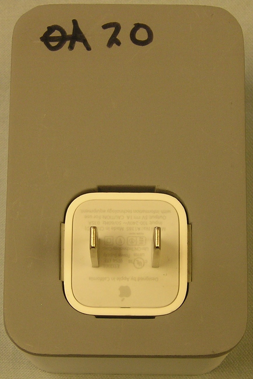
External Photos

↗

ID Label/Location Info

↗

Internal Photos

↗

Test Report

↗

Test Setup Photos

↗

Document Text

Text extracted from the exhibit documents filed with the FCC. Open a document above to read the original.

Users Manual

Questions? Go to getnotion.com/help for support. 0304 Follow the app’s instructions to set up your sensors. Place your sensors following the on-screen tips. 0102 Tap in the Notion app to open the settings menu. From the settings menu, select “Add new sensor.” This equipment has been tested and found to comply with the limits for a Class B digital device, pursuant to part 15 of FCC Rules. These limits are designed to provide reasonable protection against harmful interference in a residential installation. This equipment generates and can radiate radio frequency energy and, if not installed and used in accordance with the instructions, may cause harmful interference to radio communications. However, there is no guarantee that interference will not occur in a particular installation. If this equipment does cause harmful interference to radio or television reception, which can be determined by turning the equipment off and on, the user is encouraged to try to correct the interference by one or more of the following measures: Reorient or relocate the receiving antenna. Increase the separation between the equipment and receiver. Connect the equipment into an outlet on a circuit different from that to which the receiver is connected. Consult the dealer or an experienced radio/TV technician for help. This device complies with part 15 of the FCC Rules. Operation is subject to the following two conditions: (1) This device may not cause harmful interference, and (2) this device must accept any interference received, including interference that may cause undesired operation. This equipment complies with FCC and IC RF (Radio Frequency) exposure limits set forth for an uncontrolled environment. This equipment should be installed and operated with a minimum separation distance of 20 centimeters between the device/antenna and the user's head/body. Caution: Changes or modifications not expressly approved by the party responsible for compliance could void the user's authority to operate this equipment. This device complies with Industry Canada licence-exempt RSS standard(s). Operation is subject to the following two conditions: (1) this device may not cause interference, and (2) this device must accept any interference, including interference that may cause undesired operation of the device. Le présent appareil est conforme aux CNR d'Industrie Canada applicables aux appareils radio exempts de licence. L'exploitation est autorisée aux deux conditions suivantes : (1) l'appareil ne doit pas produire de brouillage, et (2) l'utilisateur de l'appareil doit accepter tout brouillage radioélectrique subi, même si le brouillage est susceptible d'en compromettre le fonctionnement. CAN ICES-3 (B)/NMB-3(B) A few details. Box may contain equipment pertaining to: FCC ID: 2AE5C-5280-S1 and IC: 20391-5280S1

Users Manual

Quick Start Guide 01 Plug the bridge into any centrally located power outlet. Your new bridge needs some juice to wake up from its nap before you get started. 02 Download the Notion app. Visit the Apple App Store, the Google Play Store, or getnotion.com/app to download the Notion app on your smartphone. 03 Register your account. Sign up and follow the instructions to set up your Notion sensors. 04 Stay connected to your home. Set up custom alerts tailored to your home. Let Notion focus on the little stuff, so you can focus on the things you love. Need help? Call us at (877) 668-4660 Email us at [email protected] Tweet us @notion Box may contain equipment pertaining to: FCC ID: 2AE5C-5280-S1 and IC: 20391-5280S1 | FCC ID: 2AE5C-5280-B1 and IC: 20391-5280B1 This equipment has been tested and found to comply with the limits for a Class B digital device, pursuant to part 15 of FCC Rules. These limits are designed to provide reasonable protection against harmful interference in a residential installation. This equipment generates and can radiate radio frequency energy and, if not installed and used in accordance with the instructions, may cause harmful interference to radio communications. However, there is no guarantee that interference will not occur in a particular installation. If this equipment does cause harmful interference to radio or television reception, which can be determined by turning the equipment off and on, the user is encouraged to try to correct the interference by one or more of the following measures: Reorient or relocate the receiving antenna. Increase the separation between the equipment and receiver. Connect the equipment into an outlet on a circuit different from that to which the receiver is connected. Consult the dealer or an experienced radio/TV technician for help. This device complies with part 15 of the FCC Rules. Operation is subject to the following two conditions: (1) This device may not cause harmful interference, and (2) this device must accept any interference received, including interference that may cause undesired operation. This equipment complies with FCC and IC RF (Radio Frequency) exposure limits set forth for an uncontrolled environment. This equipment should be installed and operated with a minimum separation distance of 20 centimeters between the device/antenna and the user’s head/body. Caution: Changes or modifi cations not expressly approved by the party responsible for compliance could void the user’s authority to operate this equipment. This device complies with Industry Canada licence-exempt RSS standard(s). Operation is subject to the following two conditions: (1) this device may not cause interference, and (2) this device must accept any interference, including interference that may cause undesired operation of the device. Le prĂ©sent appareil est conforme aux CNR d’Industrie Canada applicables aux appareils radio exempts de licence. L’exploitation est autorisĂ©e aux deux conditions suivantes : (1) l’appareil ne doit pas produire de brouillage, et (2) l’utilisateur de l’appareil doit accepter tout brouillage radioĂ©lectrique subi, mĂŞme si le brouillage est susceptible d’en compromettre le fonctionnement. CAN ICES-3 (B)/NMB-3(B) In order to comply with the maximum permissible exposure (MPE) limit for radio frequency (RF) energy allowed by both the FCC and IC, the bridge must be placed no closer than 20 cm to the operator during normal operatione placed no closer than 20 cm to the operator during normal operation Afi n de se conformer Ă  l’exposition tolĂ©rĂ©e (EMT) limite maximale pour la frĂ©quence radio (RF) a permis Ă  la fois par la FCC et IC , le pont doit ĂŞtre placĂ© pas moins de 20 cm Ă  l’opĂ©rateur pendant le fonctionnement normal . Happy Monitoring!

Block Diagram

Block Diagram - Bridge CC2538 f = <2405 – 2480 MHz> RF-P RF-N PA LNA Frequency Synthesizer f_internal = <4810 – 4960 MHz> f_output = <2405 – 2480 MHz> IQ IQ Clock Mux 16 MHz RC OSC 32 kHz RC OSC 32 MHz Crystal Osc I Q Radio I/O, MAC, Data Interface and Control Logic ARM Cortex-M3 LEDs I Q RIGADO MODULE FCC ID: 2AA9B03 IC: 12208A-01 f = <2402 – 2480 MHz> AZUREWAVE MODULE FCC ID: TLZ-CU288 IC: 6100A-CU288 f = <2412 – 2462 MHz> Block Diagram of Bridge showing all oscillators and functional blocks where they reside

Cover Letter(s)

DATE : July 8th, 2015 Nemko Canada Inc 303 River Road Ottawa, Ontario, Canada K1V 1H2 Attn: Director of Certification Authority to Act as Agent FCC On our behalf, I appoint Pat Schroepfer of EMC Integrity at 1736 Vista View Drive, Longmont, CO 80504 to act as our agent in the preparation of this application for equipment certification. I certify that submitted documents properly describe the device or system for which equipment certification is sought. I also certify that each unit manufactured, imported or marketed, as defined in FCC regulations will have affixed to it a label identical to that submitted for approval with this application. In signing this letter, Applicant certifies that neither the applicant nor any party to the application is not subject to a denial of Federal benefits, that include FCC benefits, pursuant to Section 5301 of the Anti-Drug Abuse Act of 1988, 21 U.S.C. § 862 because of a conviction for possession or distribution of a controlled substance. See 47 CFR 1.2002(b) for the definition of a "party" for these purposes. For instances where our authorized agent signs the application for certification on our behalf, I acknowledge that all responsibility for complying with the terms and conditions for certification, as specified by Nemko Canada Inc, still resides (company name and address). Dated this 8 Day of July 20 15 Agency agreement expiration date: July 8 th , 2016 By: Ryan Margoles Signature Printed Title: Co-Founder, CTO On behalf of : Loop Labs, Inc. dba Notion Telephone: 303-875-7176

Cover Letter(s)

N emko Canada Inc. 303 River Road Ottawa, Ontario, Canada K1V 1H2 F CC ID: 2AE5C-5280-B1 P roduct Name: Bridge Request for Confidentiality P ursuant to Sections 0.457 and 0.459 of the Commissions rules, we hereby request that the following documents be held confidential: •S chematics • Bill of Materials These materials contain trade secrets and proprietary information and are not customarily released to the public. The public disclosure of this information might be harmful to the company and provide unjustified benefits to our competitors. Dated this 27th Day of August 20 15 By: Ryan Margoles Signature Printed Title: Co-Founder, CTO On behalf of : Loop Labs, Inc. dba Notion Telephone: 303-875-7176 • Operating/Technical Description

Test Report

EMC Integrity, Inc. 1736 Vista View Drive Longmont, CO 80504 USA Page 1 of 92 Tel: +1 303-776-7249 Fax: +1 303-776-7314 NVLAP Lab Code 200737-0 This report must not be used to claim product certification, approval, or endorsement by NVLAP, NIST, or any agency of the Federal Government. EMCI, Inc. is a NVLAP accredited laboratory . Test Report issued under the responsibility of: TEST REPORT FCC Part 15 Radio Frequency Devices Subpart C – Intentional Radiators Report Reference No. ..................... : ETRB50504, Rev. A Compiled by (+ signature) ............... : Kevin Johnson. Approved by (+ signature) ................ : Vincent W. Greb Date of issue .................................... : 31 August 2015 Report Revision ............................... : Initial Release Total number of pages ..................... : 92 Testing Laboratory ......................... : EMC Integrity, Inc. Address ............................................ : 1736 Vista View Drive. Longmont, CO 80504 USA FRN: 0015264914 IC Registration Number: 7726A Tel: +1 303-776-7249 Fax: +1 303-776-7314 Applicant’s name ............................ : Loop Labs, Inc. Address ............................................. : 1530 Blake Street, Suite 220, Denver, CO 80202 Model(s) Tested ............................... : 0002 Test specification: Standard ........................................... : FCC Part 15, Subpart C, , DTS 247 (v03r02), RSS-247 (Issue 1) Test procedure .................................. : ANSI C63.4:2009, ANSI C63.10: 2013 Non-standard test method ................ : N/A TRF Revision .................................... : 31 August 2015 FCC Part 15, Subpart C Report #: ETRB50504, Rev. A Issue Date: 31 August 2015 EMC Integrity, Inc. 1736 Vista View Drive Longmont, CO 80504 USA Page 2 of 92 Tel: +1 303-776-7249 Fax: +1 303-776-7314 Revision History # Description Date - Initial Report Release 7 August 2015 A Revised MPE calculation with correct max power level 31 August 2015 Notices: 1.This report shall not be reproduced, except in full, without the written approval of the Issuing testing laboratory. 2.The test results presented in this report relate only to the object tested. 3.The results contained in this report reflect the results for this particular model and serial number. It is the responsibility of the manufacturer to ensure that all production models meet the intent of the requirements detailed within this report. 4."(See Enclosure #)" refers to additional information appended to the report. 5.Throughout this report a point is used as the decimal separator. 6.Dimensions in English units for convenience only, metric units prevail. FCC Part 15, Subpart C Report #: ETRB50504, Rev. A Issue Date: 31 August 2015 EMC Integrity, Inc. 1736 Vista View Drive Longmont, CO 80504 USA Page 3 of 92 Tel: +1 303-776-7249 Fax: +1 303-776-7314 Table of Contents Revision History ................................................................................................................................................................. 2 Normative References ........................................................................................................................................................ 4 Equipment Under Test (EUT) ............................................................................................................................................. 5 Details: ........................................................................................................................................................................... 5 EUT Configuration ......................................................................................................................................................... 6 EUT Photo(s) ................................................................................................................................................................. 9 Summary of Testing ........................................................................................................................................................... 11 Testing Location ........................................................................................................................................................... 12 Procedural Requirements ............................................................................................................................................ 12 United States ........................................................................................................................................................... 12 Information to the User and Labeling Requirements ................................................................................................... 12 United States ........................................................................................................................................................... 13 Technical Requirements ................................................................................................................................................... 14 Conducted Emissions ....................................................................................................................................................... 14 Mains ............................................................................................................................................................................ 14 Radiated Emissions – Restricted Bands .......................................................................................................................... 15 Restricted Bands 47 CFR 15.205 ............................................................................................................................ 16 Radiated Emission Limit – Restricted Bands ........................................................................................................... 16 DTS - Bandwidth ...........…

Text truncated - open the document above for the full version.

Contact Information

Applicant

Thomas Fad(VP and GM Connected Home)
[email protected]512-423-2355Fax: 1-877-668-4660

Technical Contact

Loop Labs Inc.Sean Fendt
[email protected]

Denver · United States

Non-Technical Contact

EMC Integrity Inc.Pat Schroepfer
[email protected]

Test Firm

EMC Integrity, Inc.Mike Wolf
[email protected]303-776-7249Fax: 303-776-7314

Technical Specifications

#Rule PartsFrequency RangePower Output
115C2.40 GHz - 2.48 GHz2.30 mW
Confidentiality
Long Term
Grant Notes
Output power listed is conducted. The antenna(s) used for this transmitter must be installed to provide a separation distance of at least 20 cm from all persons and must not be co-located or operating in conjunction with any other antenna or transmitter, except as documented in this filing. End-users and installers must be provided with antenna installation and transmitter operating conditions for satisfying RF exposure compliance.

Other Applications from Comcast Neptune, LLC dba Notion

Notion-Sensor - FCC ID 2AE5C-5280-S1 - Comcast Neptune, LLC dba Notion
2AE5C-5280-S1

Notion-Sensor

Sep 08, 2015

Equipment Class

DTS - Digital Transmission System