2AE7RSANTOKQ65Mobile Phone
Santok Limited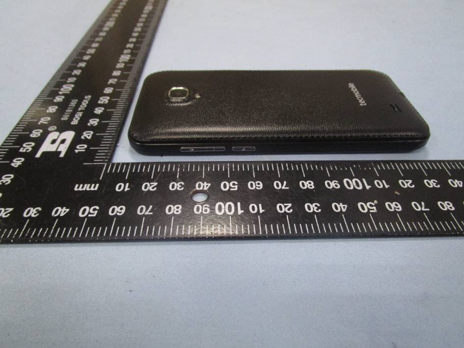
Click to zoom
Application Details
- Equipment Class
- DSS - Part 15 Spread Spectrum Transmitter
- Date of Grant
- Jul 26, 2015
- Application Purpose
- Original Equipment
- Date of Application
- Jul 26, 2015
- Equipment Note
- Mobile Phone
- Frequency Range
- 2402.00000000 - 2480.00000000
- Company
- Santok Limited
- Country
- United Kingdom
Documents & Files
Document Text
Text extracted from the exhibit documents filed with the FCC. Open a document above to read the original.
Users Manual
1 Phone user manual User Guide Q65 Preface Thank you for choosing Q65 mobile phone! Q65 is an Android intelligent mobile phone, it has the ultra-thin fashion appearance, it supports application software installation and unloading from Android electronic market, WLAN network connection, touch capacitive screen, high-pixels cameras, high-quality audio and ultra HD video, etc. These will lead you into an entirely new and fascinating mobile internet world. This manual systematically introduces many functions of Q65 mobile phone, tips and notes. Please carefully read it before using Q65. The illustrations in this manual are only for reference, and their functions are based on the real product . The company reserves the right of final interpretation. 2 Basic Information 1. Safety Notice If your phone is lost or stolen, please immediately inform the telecom department or commission agents of forbidding the use of SIM card, so that avoid the economic loss caused by false calling of others. When you contact with telecom department or commission agents, they need to know your phone IMEI number (printed on the label on the back of the phone and can be found after taking down the battery). Please copy the number and keep it safe for future use. In order to use the phone more safely, please adopt preventive measures, for example: set up the PIN code of SIM card, PIN code can prevent your SIM card from being used by others without permission. When leaving the car, please don’t place the phone in a place easy to be seen, you had better to carry with you or lock in the suitcase. 2. Safety Alert and Cautions Before using the phone, please read these cautions carefully so that make sure to use the phone correctly. 3.1 General Cautions On the plane, in the hospital and other places that forbidden to use the mobile phone, please turn off the phone; otherwise it may affect the normal operation of electronic equipments and medical instruments. Please comply with the relevant regulations if using the phone in these places, Please strictly comply with the laws and regulations about the phone use in the driving place. If you use the phone while you are driving, please comply with the following rules: concentrate on driving, pay attention to the road conditions; if the phone has hands-free function, please make a phone call hands-free; if the driving conditions are not good, please stop the car, and then dial or receive a call. When approaching the places that storing fuel, chemicals or explosives, and etc., please comply with the laws, regulations and the relevant signs. Please place the phone, battery and charger in the place out of children’s reach, for fear that the children use them as tools and cause personal injury. Your phone only can use the batteries, chargers and other accessories specified by the company for fear that the phone is damaged. If using other batteries and chargers, it may cause liquid leaking, overheat, explosion, fire breakout and other failures of batteries. Please don’t use the phone close to weak signal or high precision electronic equipments. Wireless wave interference may cause the mis-operation of these electronic equipments. The phone has the function of timely auto power-on, please check the auto power-on and shut down settings of the phone, so that confirm that the phone will not power on automatically during the flight. Please don’t strike, shake or sling the phone violently for fear that the phone is failed or fire breakout. Please don’t place the battery, the phone and the charger in the micro-wave oven or high-voltage equipment; otherwise may cause circuit damage or fire breakout and other accidents. Please don’t use the phone in the places with inflammable and explosive gas; otherwise may cause phone failure or fire hazard. 3 Please don’t place the phone in the places with high temperature, high humidity or a large amount of dust; otherwise it may cause phone failure. Please don’t place the phone in the uneven or unstable place, prevent the phone from falling off and then cause failure or damage. Please only use the original antenna or the antenna being approved by the company. Unapproved and modified antenna or the antenna with additional accessories may damage the phone. Please don’t touch the antenna during a call. Touching the antenna may affect the call quality and make the phone power higher than the required power in normal use. In addition, using the unapproved antenna may violate the regulations in your country. 3.2 Cautions of Using the Phone Don’t take down or modify the phone; otherwise it may cause the damage, leakage and circuit failure of the phone. Please don’t knock the LCD by force or use the LCD to knock other things; otherwise may cause the damage of liquid crystal plate and the leaking of liquid crystal. If liquid crystal enters the eyes, it may damage eyesight. At this time, please rinse the eyes immediately with clean water (don’t rub the eyes), and see a doctor immediately. In very rare cases, if the phone is used in some types of vehicles, it may have bad effect on the electronic equipments in the vehicle. At this time, please don’t use the phone for fear of losing the safety guarantee. If your vehicle is equipped with the air bag, please don’t place the phone above the air bag or the area that can be touched after the air bag is swelled, for fear that the phone is applied very strong external force and cause serious damage on the vehicle owner when the air bag is swelled. Please don’t touch the key-stoke using needles, pen nibs and other sharp objects; otherwise it may damage the phone or cause mis-operation. If the antenna is damaged, please don’t use the phone; otherwise it may cause the personal injury. Don’t make the phone approach to the magnetic card and other magnetic objects too closely; radiation wave of the phone may clean out the information stored in the floppy disks, stored value cards and credit cards. Please place the drawing pin and…
Text truncated - open the document above for the full version.
External Photos
Santok Limited Model: Q65 REPORT NO.: STR15068223I-1 FCC PART 22H&24E EXHIBIT 2 - EUT EXTERNAL PHOTOGRAPHS EUT View 1 EUT View 2 Santok Limited Model: Q65 REPORT NO.: STR15068223I-1 FCC PART 22H&24E EUT View 3 EUT View 4 Santok Limited Model: Q65 REPORT NO.: STR15068223I-1 FCC PART 22H&24E EUT View 5 EUT View 6 Santok Limited Model: Q65 REPORT NO.: STR15068223I-1 FCC PART 22H&24E EUT View 7
ID Label/Location Info
Santok Limited Model: Q65 REPORT NO.: STR15068223I-1 FCC PART 22H&24E EXHIBIT 1 - PRODUCT LABELING Proposed FCC ID Label Format FCC ID: 2AE7RSANTOKQ65 This device complies with Part 15 of the FCC Rules. Operation is subject to the following two conditions: (1) This device may not cause harmful interference, and (2) this device must accept any interference received, including interference that may cause undesired operation. Specifications: Text is Black in color and justified. Labels are printed in indelible ink on permanent adhesive silk-screened onto the EUT or shall be affixed at a conspicuous location on the EUT. Proposed Label Location on EUT FCC ID Label Location
Internal Photos
Santok Limited Model: Q65 REPORT NO.: STR15068223I-1 FCC PART 22H&24E EXHIBIT 3 - EUT INTERNAL PHOTOGRAPHS EUT Housing and Board View 1 EUT Housing and Board View 2 Santok Limited Model: Q65 REPORT NO.: STR15068223I-1 FCC PART 22H&24E EUT Housing and Board View 3 Solder Board-Component View 1 Santok Limited Model: Q65 REPORT NO.: STR15068223I-1 FCC PART 22H&24E Solder Board-Component View 2 Solder Board-Component View 3 Santok Limited Model: Q65 REPORT NO.: STR15068223I-1 FCC PART 22H&24E Solder Board-Component View 4 Antenna View GPS/WIFI/BT Antenna GSM/WCDMA Antenna
Test Report
Santok Limited Model: Q65 REPORT NO.: STR15068223I-2 PAGE 1 OF 56 FCC PART 15.247 FCC Part 15C Measurement and Test Report For Santok Limited Santok House, Unit L, Braintree Industrial Estate, Braintree Road, South Ruislip, Middlesex, HA4 0EJ United Kingdom FCC ID: 2AE7RSANTOKQ65 FCC Rule(s): FCC Part 15.247 Product Description: Mobile Phone Tested Model: Q65 Report No.: STR15068223I-2 Tested Date: 2015-06-26 to 2015-07-08 Issued Date: 2015-07-08 Tested By: Lebron Wang / Engineer Reviewed By: Lahm Peng / EMC Manager Approved & Authorized By: Jandy So / PSQ Manager Prepared By: Shenzhen SEM.Test Technology Co., Ltd. 1/F, Building A, Hongwei Industrial Park, Liuxian 2nd Road, Bao'an District, Shenzhen, P.R.C.(518101) Tel.: +86-755-33663308 Fax.: +86-755-33663309 Website: www.semtest.com.cn Note: This test report is limited to the above client company and the product model only. It may not be duplicated without prior permitted by Shenzhen SEM.Test Technology Co., Ltd. Santok Limited Model: Q65 REPORT NO.: STR15068223I-2 PAGE 2 OF 56 FCC PART 15.247 TABLE OF CONTENTS 1. GENERAL INFORMATION ................................................................................................................................... 4 1.1 PRODUCT DESCRIPTION FOR EQUIPMENT UNDER TEST (EUT) ............................................................................... 4 1.2 TEST STANDARDS ................................................................................................................................................... 6 1.3 TEST METHODOLOGY ............................................................................................................................................. 6 1.4 TEST FACILITY ....................................................................................................................................................... 6 1.5 EUT SETUP AND TEST MODE ................................................................................................................................. 7 2. SUMMARY OF TEST RESULTS ........................................................................................................................... 8 3. RF EXPOSURE ......................................................................................................................................................... 9 3.1 STANDARD APPLICABLE ......................................................................................................................................... 9 3.2 TEST RESULT.......................................................................................................................................................... 9 4. ANTENNA REQUIREMENT ................................................................................................................................ 10 4.1 STANDARD APPLICABLE ....................................................................................................................................... 10 4.2 EVALUATION INFORMATION ................................................................................................................................ 10 5. FREQUENCY HOPPING SYSTEM REQUIREMENTS ................................................................................... 11 5.1 STANDARD APPLICABLE ....................................................................................................................................... 11 5.2 FREQUENCY HOPPING SYSTEM............................................................................................................................. 11 5.3 EUT PSEUDORANDOM FREQUENCY HOPPING SEQUENCE .................................................................................... 12 6. QUANTITY OF HOPPING CHANNELS AND CHANNEL SEPARATION ................................................... 13 6.1 STANDARD APPLICABLE ....................................................................................................................................... 13 6.2 TEST EQUIPMENT LIST AND DETAILS ................................................................................................................... 13 6.3 TEST PROCEDURE ................................................................................................................................................. 13 6.4 ENVIRONMENTAL CONDITIONS ............................................................................................................................ 13 6.5 SUMMARY OF TEST RESULTS/PLOTS .................................................................................................................... 14 7. DWELL TIME OF HOPPING CHANNEL .......................................................................................................... 18 7.1 STANDARD APPLICABLE ....................................................................................................................................... 18 7.2 TEST EQUIPMENT LIST AND DETAILS ................................................................................................................... 18 7.3 TEST PROCEDURE ................................................................................................................................................. 18 7.4 ENVIRONMENTAL CONDITIONS ............................................................................................................................ 18 7.5 SUMMARY OF TEST RESULTS/PLOTS .................................................................................................................... 19 8. 20DB BANDWIDTH ............................................................................................................................................... 29 8.1 STANDARD APPLICABLE ....................................................................................................................................... 29 8.2 TEST EQUIPMENT LIST AND DETAILS ............................…
Text truncated - open the document above for the full version.
Test Setup Photos
Santok Limited Model: Q65 REPORT NO.: STR15068223I-2/3/4 FCC PART 15.247 EXHIBIT 4 - TEST SETUP PHOTOGRAPHS Conducted Emission Test Setup Radiation Emission Test Setup (Below 30MHz) Santok Limited Model: Q65 REPORT NO.: STR15068223I-2/3/4 FCC PART 15.247 Radiation Emission Test Setup (30MHz to 1GHz) Radiation Emission Test Setup (Above 1GHz)
Contact Information
Applicant
Brian Preston(Head of Product & Service)
Test Firm
Shenzhen SEM.Test Technology Co., Ltd.Jandy So
Technical Specifications
| # | Rule Parts | Frequency Range | Power Output |
|---|---|---|---|
| 1 | 15C | 2.40 GHz - 2.48 GHz | 1.00 mW |
Other Applications from Santok Limited

2AE7RSTKGALACTIC6
Dec 16, 2015SMARTPHONE
Equipment Class
DTS - Digital Transmission System
2AE7RSANTOKSYNC5C
Dec 15, 20153G smart phone
Equipment Class
PCE - PCS Licensed Transmitter held to ear