2AEBTA850Mobile Phone
Shenzhen Huibaizhou Electronics Co., Ltd.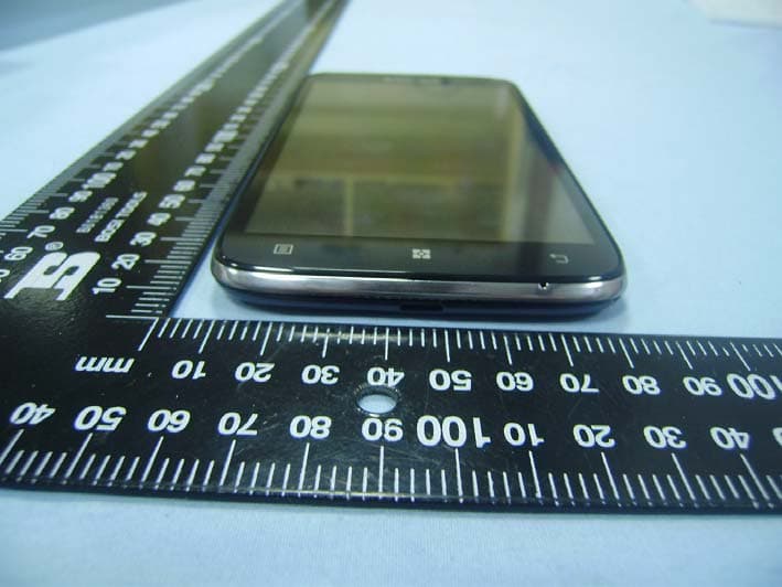
Click to zoom
Application Details
- Equipment Class
- PCE - PCS Licensed Transmitter held to ear
- Date of Grant
- Mar 12, 2015
- Application Purpose
- Original Equipment
- Date of Application
- Mar 12, 2015
- Equipment Note
- Mobile Phone
- Frequency Range
- 1850.20000000 - 1909.80000000
- Country
- China
Documents & Files
Document Text
Text extracted from the exhibit documents filed with the FCC. Open a document above to read the original.
Users Manual
Important Product Information Guide v1.0 Lenovo A850 Content Important safety and handling information .............................................. 2 Service and Support information........................................................... 10 Warranty information ............................................................................. 11 Environmental, recycling, and disposal information .............................. 14 Restriction of Hazardous Substances Directive (RoHS) ........................ 15 Specific Absorption Rate information .................................................... 17 Important safety and handling information Important safety and handling information Important safety information CAUTION To avoid personal injury, property damage, or accidental damage to Lenovo Phone, read all of the information in this section before using it. Handling Handle Lenovo Phone with care Do not drop, bend, puncture, insert foreign objects, or place heavy objects on Lenovo Phone. Sensitive components inside might become damaged. Prevent Lenovo Phone and adapter from getting wet Do not immerse Lenovo Phone in water or leave it in a location where it can get saturated with water or other liquids. Repairing Do not disassemble or modify Lenovo Phone. Lenovo Phone is a sealed unit. There are no end-user serviceable parts inside. All internal repairs must be done by a Lenovo-authorized repair facility or a Lenovo-authorized technician. Attempting to open or modify Lenovo Phone will void the warranty. Lenovo Phone screen is made of glass. The glass might break if Lenovo Phone is dropped on a hard surface, is the subject of a high impact, or is crushed by a heavy object. If the glass chips or cracks, do not touch the broken glass or attempt to remove it from Lenovo Phone. Stop using Lenovo Phone immediately and contact Lenovo ® technical support for repair, replacement, or disposal information. Important safety and handling information Battery Built-in rechargeable battery notice DANGER Do not attempt to replace the internal rechargeable lithium ion battery. Contact Lenovo Support for factory replacement. Lithium coin cell battery notice DANGER Charging Charge Lenovo Phone in the temperature range of 0°C(32 °F) - 50°C(122°F).You can use any of the following charging methods to safely recharge the internal battery of Lenovo Phone: Charging method Display is on Display is off AC adapter Approved, but the battery will charge slowly. Approved A USB connection between the dc-in connector on Lenovo Phone and a USB connector of a personal computer or other device that complies with the USB 2.0 standards This charging method will compensate the power consumption. The battery will discharge more slowly than usual. Approved, but the battery will charge slowly. NOTES: Display is on : Lenovo Phone on Display is off : Lenovo Phone off or in screen lock mode Charging devices might become warm during normal use. Ensure that you have adequate ventilation around the charging device. Unplug the Important safety and handling information charging device if any of the following occurs: The charging device has been exposed to rain, liquid, or excessive moisture. The charging device shows signs of physical damage. You want to clean the charging device. Lenovo is not responsible for the performance or safety of products not manufactured or approved by Lenovo. Distraction Take care when using Lenovo Phone in a motor vehicle or on a bicycle. Always prioritize your safety and the safety of others. Follow the law. Local laws and regulations might govern how you can use mobile electronic devices, such as Lenovo Phone, while you drive a motor vehicle or ride a bicycle. Choking hazard Keep Lenovo Phone and accessories away from small children. Lenovo Phone contains small parts that can be a choking hazard to small children. Additionally, the glass screen can break or crack if dropped on or thrown against a hard surface. Plastic bag notice CAUTION Plastic bags can be dangerous. Keep plastic bags away from babies and children to avoid danger of suffocation. Important safety and handling information Prevent hearing damage Lenovo Phone has a headphone connector. Always use the headphone connector for headphones (also called a headset) or earphones. CAUTION Excessive sound pressure from earphones and headphones can cause hearing loss. Adjustment of the equalizer to maximum increases the earphone and headphone output voltage and the sound pressure level. Therefore, to protect your hearing, adjust the equalizer to an appropriate level. Excessive use of headphones or earphones for a long period of time at high volume can be dangerous if the output of the headphone or earphone connectors do not comply with specifications of EN 50332-2. The headphone output connector of Lenovo Phone complies with EN 50332-2 Sub clause 7. This specification limits Lenovo Phone's maximum wide band true RMS output voltage to 150 mV. To help protect against hearing loss, ensure that the headphones or earphones you use also comply with EN 50332-2 (Clause 7 limits) for a wide band characteristic voltage of 75 mV. Using headphones that do not comply with EN 50332-2 can be dangerous due to excessive sound pressure levels. If Lenovo Phone came with headphones or earphones in the package, as a set, the combination of the headphones or earphones and Lenovo Phone already complies with the specifications of EN 50332-1. If different headphones or earphones are used, ensure that they comply with EN 50332-1 (Clause 6.5 Limitation Values). Using headphones that do not comply with EN 50332-1 can be dangerous due to excessive sound pressure levels. Sound Pressure Warning statement For the device which tests accordance to EN 60950-1: Important safety and handling information 2006+A11:2009:+A1:2010+A12:2011, it is mandatory to perform audio tests for EN50332. This device have been tested to comply with the Sound Pressure Level requirement laid down in …
Text truncated - open the document above for the full version.
External Photos
Shenzhen Huibaizhou Electronics Co., Ltd Model: A850 REPORT NO.: STR15028110I-1 FCC PART 22H&24E EXHIBIT 2 - EUT EXTERNAL PHOTOGRAPHS EUT View 1 EUT View 2 Shenzhen Huibaizhou Electronics Co., Ltd Model: A850 REPORT NO.: STR15028110I-1 FCC PART 22H&24E EUT View 3 EUT View 4 Shenzhen Huibaizhou Electronics Co., Ltd Model: A850 REPORT NO.: STR15028110I-1 FCC PART 22H&24E EUT View 5 EUT View 6 Shenzhen Huibaizhou Electronics Co., Ltd Model: A850 REPORT NO.: STR15028110I-1 FCC PART 22H&24E EUT View 7
ID Label/Location Info
Shenzhen Huibaizhou Electronics Co., Ltd Model: A850 REPORT NO.: STR15028110I-1 FCC PART 22H&24E EXHIBIT 1 - PRODUCT LABELING Proposed FCC ID Label Format FCC ID: 2AEBTA850 This device complies with Part 15 of the FCC Rules. Operation is subject to the following two conditions: (1) This device may not cause harmful interference, and (2) this device must accept any interference received, including interference that may cause undesired operation. Specifications: Text is Black in color and justified. Labels are printed in indelible ink on permanent adhesive silk-screened onto the EUT or shall be affixed at a conspicuous location on the EUT. Proposed Label Location on EUT FCC ID Label Location
Internal Photos
Shenzhen Huibaizhou Electronics Co., Ltd Model: A850 REPORT NO.: STR15028110I-1 FCC PART 22H&24E EXHIBIT 3 - EUT INTERNAL PHOTOGRAPHS EUT Housing and Board View 1 EUT Housing and Board View 2 Shenzhen Huibaizhou Electronics Co., Ltd Model: A850 REPORT NO.: STR15028110I-1 FCC PART 22H&24E Solder Board-Component View 1 Solder Board-Component View 2 Shenzhen Huibaizhou Electronics Co., Ltd Model: A850 REPORT NO.: STR15028110I-1 FCC PART 22H&24E Solder Board-Component View 3 Solder Board-Component View 4 Shenzhen Huibaizhou Electronics Co., Ltd Model: A850 REPORT NO.: STR15028110I-1 FCC PART 22H&24E Solder Board-Component View 5 Antenna View 1 GSM Antenna WIFI/BT Antenna
RF Exposure Info
Shenzhen Huibaizhou Electronics Co., Ltd Model: A850 Report No.: STR15028110H Page 1 of 98 SAR Report FCC SAR Measurement and Test Report For Shenzhen Huibaizhou Electronics Co., Ltd Room 1011, Hualianfa building, Huaqiang North Road, Futian District, Shenzhen City, Guangdong Province FCC ID: 2AEBTA850 FCC Rules: FCC 47 CFR Part 2 (2.1093) ANSI/IEEE C95.1-1992 IEEE 1528-2003 KDB 865664 D01 v01r03 KDB 865664 D02 v01r01 Product Description: Mobile Phone Tested Model: A850 Report No.: STR15028110H Tested Date: 2015-03-02 to 2015-03-06 Issued Date: 2015-03-09 Tested By: Lucy Wei / Engineer Reviewed By: Lahm Peng / EMC Manager Approved & Authorized By: Jandy So / PSQ Manager Prepared By: Shenzhen SEM.Test Technology Co., Ltd. 1/F, Building A, Hongwei Industrial Park, Liuxian 2nd Road, Bao'an District, Shenzhen, P.R.C.(518101) Tel.: +86-755-33663308 Fax.: +86-755-33663309 Website: www.semtest.com.cn Note: This test report is limited to the above client company and the product model only. It may not be duplicated without prior permitted by Shenzhen SEM. Test Technology Co., Ltd. Shenzhen Huibaizhou Electronics Co., Ltd Model: A850 Report No.: STR15028110H Page 2 of 98 SAR Report TABLE OF CONTENTS 1. General Information ................................................................................................................................................... 3 1.1 Product Description for Equipment Under Test (EUT) ......................................................................................... 3 1.2 Test Standards .................................................................................................................................................... 5 1.3 Test Methodology ................................................................................................................................................ 5 1.4 Test Facility ......................................................................................................................................................... 5 2. Summary of Test Results .......................................................................................................................................... 6 3. Specific Absorption Rate (SAR) ................................................................................................................................ 7 3.1 Introduction .......................................................................................................................................................... 7 3.2 SAR Definition ..................................................................................................................................................... 7 4. SAR Measurement System ........................................................................................................................................ 8 4.1 The Measurement System .................................................................................................................................. 8 4.2 Probe ................................................................................................................................................................... 8 4.3 Probe Calibration Process ................................................................................................................................. 10 4.4 Phantom ............................................................................................................................................................ 11 4.5 Device Holder .................................................................................................................................................... 11 4.6 Test Equipment List ........................................................................................................................................... 12 5. Tissue Simulating Liquids ....................................................................................................................................... 13 5.1 Composition of Tissue Simulating Liquid ........................................................................................................... 13 5.2 Tissue Dielectric Parameters for Head and Body Phantoms ............................................................................. 14 5.3 Tissue Calibration Result ................................................................................................................................... 15 6. SAR Measurement Evaluation ................................................................................................................................ 16 6.1 Purpose of System Performance Check ............................................................................................................ 16 6.2 System Setup .................................................................................................................................................... 16 6.3 Validation Results .............................................................................................................................................. 17 7. EUT Testing Position ............................................................................................................................................... 18 7.1 Define Two Imaginary Lines on The Handset .................................................................................................... 18 7.2 Cheek Position .................................................................................................................................................. 19 7.3 Tilted Position .................................................................................................................................................... 19 7.4 Body Position ...................................................................................................................................................…
Text truncated - open the document above for the full version.
Test Report
Shenzhen Huibaizhou Electronics Co., Ltd Model: A850 REPORT NO.: STR15028110I-1 PAGE 1 OF 63 FCC PART 22H&24E FCC Part 22H & 24E Measurement and Test Report For Shenzhen Huibaizhou Electronics Co., Ltd Room 1011, Hualianfa building, Huaqiang North Road, Futian District, Shenzhen City, Guangdong Province FCC ID: 2AEBTA850 FCC Rules: FCC Part 22H, FCC Part 24E Product Description: Mobile Phone Tested Model: A850 Report No.: STR15028110I-1 Tested Date: 2015-02-26 to 2015-03-11 Issued Date: 2015-03-11 Tested By: Silin Chen / Engineer Reviewed By: Lahm Peng / EMC Manager Approved & Authorized By: Jandy So / PSQ Manager Prepared By: Shenzhen SEM.Test Technology Co., Ltd. 1/F, Building A, Hongwei Industrial Park, Liuxian 2nd Road, Bao'an District, Shenzhen, P.R.C.(518101) Tel.: +86-755-33663308 Fax.: +86-755-33663309 Website: www.semtest.com.cn Note: This test report is limited to the above client company and the product model only. It may not be duplicated without prior permitted by Shenzhen SEM. Test Technology Co., Ltd. Shenzhen Huibaizhou Electronics Co., Ltd Model: A850 REPORT NO.: STR15028110I-1 PAGE 2 OF 63 FCC PART 22H&24E TABLE OF CONTENTS 1. GENERAL INFORMATION ................................................................................................................................... 3 1.1 PRODUCT DESCRIPTION FOR EQUIPMENT UNDER TEST (EUT) ............................................................................... 3 1.2 TEST STANDARDS ................................................................................................................................................... 5 1.3 TEST METHODOLOGY ............................................................................................................................................. 5 1.4 TEST FACILITY ....................................................................................................................................................... 5 1.5 EUT SETUP AND TEST MODE ................................................................................................................................. 6 2. SUMMARY OF TEST RESULTS ........................................................................................................................... 7 3. RF EXPOSURE ......................................................................................................................................................... 8 3.1 STANDARD APPLICABLE ......................................................................................................................................... 8 3.2 TEST RESULT.......................................................................................................................................................... 8 4. RF OUTPUT POWER .............................................................................................................................................. 9 4.1 STANDARD APPLICABLE ......................................................................................................................................... 9 4.2 TEST EQUIPMENT LIST AND DETAILS ..................................................................................................................... 9 4.3 TEST PROCEDURE ................................................................................................................................................... 9 4.4 ENVIRONMENTAL CONDITIONS ............................................................................................................................ 10 4.5 SUMMARY OF TEST RESULTS/PLOTS .................................................................................................................... 10 5. PEAK-TO-AVERAGE RADIO (PAR) OF TRANSMITTER ............................................................................. 14 5.1 STANDARD APPLICABLE ....................................................................................................................................... 14 5.2 TEST EQUIPMENT LIST AND DETAILS ................................................................................................................... 14 5.3 TEST PROCEDURE ................................................................................................................................................. 14 5.4 ENVIRONMENTAL CONDITIONS ............................................................................................................................ 14 5.5 SUMMARY OF TEST RESULTS ............................................................................................................................... 15 6. EMISSION BANDWIDTH ..................................................................................................................................... 16 6.1 STANDARD APPLICABLE ....................................................................................................................................... 16 6.2 TEST EQUIPMENT LIST AND DETAILS ................................................................................................................... 16 6.3 TEST PROCEDURE ................................................................................................................................................. 16 6.4 ENVIRONMENTAL CONDITIONS ............................................................................................................................ 16 6.5 SUMMARY OF TEST RESULTS/PLOTS .................................................................................................................... 17 7. OUT OF BAND EMISSIONS AT ANTENNA TERMINAL ............................................................................... 27 7.1 STANDARD APPLICABLE ....................................................................................................................................... 27 7.2 TEST EQUIPMENT LIST AND DETAILS ............................................…
Text truncated - open the document above for the full version.
Test Setup Photos
Shenzhen Huibaizhou Electronics Co., Ltd Model: A850 REPORT NO.: STR15028110I-1 FCC PART 22H&24E EXHIBIT 4 - TEST SETUP PHOTOGRAPHS Spurious Radiation Test Setup (9kHz to 30MHz) Spurious Radiation Test Setup (30MHz to 1G) Shenzhen Huibaizhou Electronics Co., Ltd Model: A850 REPORT NO.: STR15028110I-1 FCC PART 22H&24E Spurious Radiation Test Setup (Above1G) Extreme Condition Test Setup Shenzhen Huibaizhou Electronics Co., Ltd Model: A850 REPORT NO.: STR15028110I-1 FCC PART 22H&24E Mobile Communication Test Setup
Contact Information
Applicant
JinWei Guo(CEO)
Test Firm
Shenzhen SEM.Test Technology Co., Ltd.Jandy So
Technical Specifications
| # | Rule Parts | Frequency Range | Power Output | Emission | Tolerance |
|---|---|---|---|---|---|
| 4 | 24E | 1.85 GHz - 1.91 GHz | 160.00 mW | 262KG7W | 0.047 ppm |
Other Applications from Shenzhen Huibaizhou Electronics Co., Ltd.

2AEBT-MI1
Jun 07, 2020Mobile Phone
Equipment Class
DSS - Part 15 Spread Spectrum Transmitter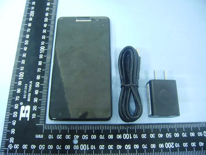
2AEBTS898T
Mar 18, 2015Mobile Phone
Equipment Class
DSS - Part 15 Spread Spectrum Transmitter