2AEHH-CL02Smart Band
Coros Wearables Inc.
Click to zoom
Application Details
- Equipment Class
- DSS - Part 15 Spread Spectrum Transmitter
- Date of Grant
- Apr 18, 2015
- Application Purpose
- Original Equipment
- Date of Application
- Apr 18, 2015
- Equipment Note
- Smart Band
- Frequency Range
- 2402.00000000 - 2480.00000000
- Company
- Coros Wearables Inc.
- Country
- United States
Documents & Files
Document Text
Text extracted from the exhibit documents filed with the FCC. Open a document above to read the original.
Users Manual
Bluetooth 4.0 Supporting List IOS 7.1 and up Android 4.4 and up iPhone 5 iPhone 5C iPhone 5S iPhone 6 Iphone 6 plus Samsung S4 Samsung S5 Samsung note3 Sony Z1(L39h) Sony Z2(L50u) LG G2(D802 LG Nexus4 LG Nexus5 Note: If your phone is not in the list : Android devices support Bluetooth 4.0 and running OS 4.4 and up. USING 01. Download Coros App Wristband needs to connect with your phone with App,Please check the Bluetooth supporting list before downloading App. > Search Please go to Apple Store or Google Play Store and search “Coros”. 02. Active Device and Charge Connect to USB charger and plug into 5V USB port, Charge until the screen turn on. 03. TOUCH Double click or long press to wake up the wristband Slide to check the functions Keep touching the screen to awake wristband 04. Launch App, Pair with your phone 主页 05. Use Now ● Time display: Sync with your phone , time will adjust automatically. ● Health:Record the information of your daily exercise , you can also check the steps,calorie,distance. ● Sleep: Enable sleep option. Wristband will record your sleeping time. ● Notifications: Incoming calls, text, twitter, facebook will display on the screen and wristband will vibrate. ● Anti-Loss: Wristband will vibrate when your phone is out of standard distance. Help ■Why my phone can not find the wristband? ① Please make sure the Bluetooth is on and your phone in the “supporting list”. ② Make sure the wristband near by your phone (within 10m). ③ Check your battery is not empty and if it is not still working. Please contact us. ■Why phone Bluetooth cannot connect with wristband? There are some unconventionality problems with few of phone Bluetooth service. Please restart your phone or Bluetooth and reconnect with it. FCC Statement: This equipment has been tested and found to comply with the limits for a Class B digital device, pursuant to Part 15 of the FCC Rules. These limits are designed to provide reasonable protection against harmful interference in a residential installation. This equipment generates uses and can radiate radio frequency energy and, if not installed and used in accordance with the instructions, may cause harmful interference to radio communications. However, there is no guarantee that interference will not occur in a particular installation. If this equipment does cause harmful interference to radio or television reception, which can be determined by turning the equipment off and on, the user is encouraged to try to correct the interference by one or more of the following measures: -- Reorient or relocate the receiving antenna. -- Increase the separation between the equipment and receiver. -- Connect the equipment into an outlet on a circuit different from that to which the receiver is connected. -- Consult the dealer or an experienced radio/TV technician for help. Changes or modifications not expressly approved by the party responsible for compliance could void the user's authority to operate the equipment. This device complies with part 15 of the FCC Rules. Operation is subject to the following two conditions: (1) This device may not cause harmful interference, and (2) this device must accept any interference received, including interference that may cause undesired operation. Hereby, Coros Wearables Inc., declares that this product is in compliance with the essential requirements and other relevant provisions of Directive 1999/5/EC.
ID Label/Location Info
Label Location:
RF Exposure Info
FCC ID: 2AEHH-CL02 The device has a standalone transmission. According to KDB 447498 section 4.3.1, the 1-g SAR test exclusion thresholds at test separation distances≤ 50 mm are determined by: [(max. power of channel, including tune-up tolerance, mW)/(min. test separation distance, mm)]·[√f(GHz)] ≤ 3.0 The maximum tune-up limit power is -3.96dBm (0.40mW) @ 2.440GHz For the head and body SAR, use 5mm as the conservative minimum test separation distance, [(max. power of channel, including tune-up tolerance, mW)/(min. test separation distance, mm)]·[√f(GHz)] =0.125≤ 3.0 So standalone SAR measurements are not required for both head and body.
Test Report
Global United Technology Services Co., Ltd. Report No.: GTSE15040040301 FCC REPORT Applicant: Coros Wearables Inc. Address of Applicant: 2755 S. Norfolk St. Apt 311,San Mateo, CA 94403 USA Equipment Under Test (EUT) Product Name: Smart Band Model No.: Coros LEAF FCC ID: 2AEHH-CL02 Applicable standards: FCC CFR Title 47 Part 15 Subpart C Section 15.247:2014 Date of sample receipt: April 08, 2015 Date of Test: April 08-14, 2015 Date of report issued: April 14, 2015 Test Result : PASS * * In the configuration tested, the EUT complied with the standards specified above. Authorized Signature: Robinson Lo Laboratory Manager This report details the results of the testing carried out on one sample. The results contained in this test report do not relate to other samples of the same product and does not permit the use of the GTS product certification mark. The manufacturer should ensure that all products in series production are in conformity with the product sample detailed in this report. This report may only be reproduced and distributed in full. If the product in this report is used in any configuration other than that detailed in the report, the manufacturer must ensure the new system complies with all relevant standards. Any mention of GTS or testing done by GTS in connection with, distribution or use of the product described in this report must be approved by GTS in writing. This document cannot be reproduced except in full, without prior written approval of the Company. Any unauthorized alteration, forgery or falsification of the content or appearance of this document is unlawful and offenders may be prosecuted to the fullest extent of the law. Unless otherwise stated the results shown in this test report refer only to the sample(s) tested and such sample(s) are retained for 90 days only. Report No.: GTSE15040040301 2 Version Version No. Date Description 00 April 14, 2015 Original Prepared By: Date: April 14, 2015 Project Engineer Check By: Date: April 14, 2015 Reviewer Global United Technology Services Co., Ltd. Project No.: GTSE150400403RF Room 301-309, 3th Floor, Block A, Huafeng Jinyuan Business Building, No. 300 Laodong Industrial Zone, Xixiang Road, Baoan District, Shenzhen, China Telephone: +86 (0) 755 2779 8480 Fax: +86 (0) 755 2779 8960 Page 2 of 38 Report No.: GTSE15040040301 3 Contents Page 1 COVER PAGE ........................................................................................................................................... 1 2 VERSION ...................................................................................................................................................2 3 CONTENTS ...............................................................................................................................................3 4 TEST SUMMARY ......................................................................................................................................4 5 GENERAL INFORMATION .......................................................................................................................5 5.1 CLIENT INFORMATION ..........................................................................................................................5 5.2 GENERAL DESCRIPTION OF EUT ..........................................................................................................5 5.3 TEST MODE .........................................................................................................................................7 5.4 DESCRIPTION OF SUPPORT UNITS ........................................................................................................7 5.5 TEST FACILITY ....................................................................................................................................7 5.6 TEST LOCATION ..................................................................................................................................7 6 TEST INSTRUMENTS LIST ......................................................................................................................8 7 TEST RESULTS AND MEASUREMENT DATA .......................................................................................9 7.1 ANTENNA REQUIREMENT ......................................................................................................................9 7.2 CONDUCTED EMISSIONS ....................................................................................................................10 7.3 CONDUCTED OUTPUT POWER ............................................................................................................13 7.4 CHANNEL BANDWIDTH .......................................................................................................................15 7.5 POWER SPECTRAL DENSITY ..............................................................................................................17 7.6 BAND EDGES .....................................................................................................................................19 7.6.1 Conducted Emission Method ......................................................................................................19 7.6.2 Radiated Emission Method .........................................................................................................20 7.7 SPURIOUS EMISSION .........................................................................................................................23 7.7.1 Conducted Emission Method ......................................................................................................23 7.7.2 Radiated Emission Method .........................................................................................................25 8 TEST SETUP PHOTO .............................................................................................................................31 9 EUT CONSTRUCTIONAL DETAILS ...........…
Text truncated - open the document above for the full version.
Test Setup Photos
Radiated Emission Conducted Emission
Contact Information
Applicant
Qiang Wu(Quality Director)
Test Firm
Global United Technology Service Co., LtdRobinson Lo
Technical Specifications
| # | Rule Parts | Frequency Range | Power Output |
|---|---|---|---|
| 1 | 15C | 2.40 GHz - 2.48 GHz | 400.00 µW |
Other Applications from Coros Wearables Inc.
2AEHH-FD05B
Apr 10, 2024COROS POD 2
Equipment Class
DTS - Digital Transmission System2AEHH-W521B
Jan 21, 2024COROS APEX 2 Pro
Equipment Class
DSS - Part 15 Spread Spectrum Transmitter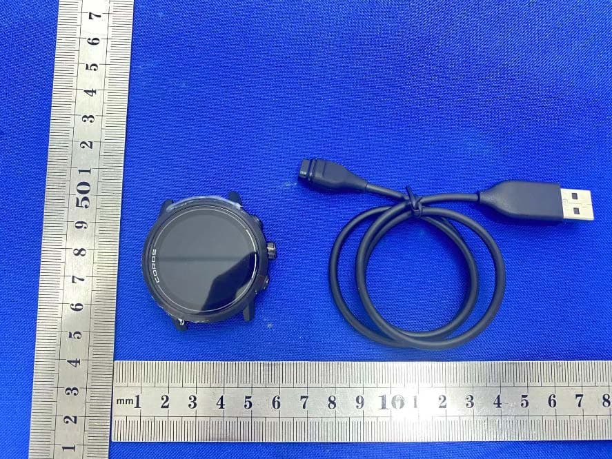
2AEHH-W522
Nov 06, 2022APEX 2
Equipment Class
DSS - Part 15 Spread Spectrum Transmitter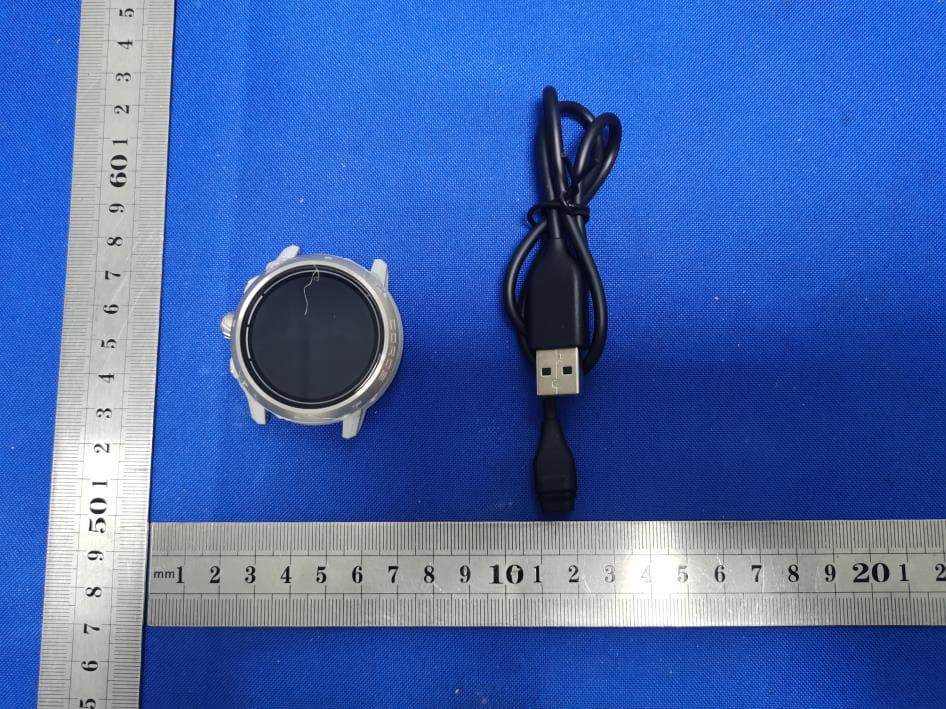
2AEHH-W521
Nov 06, 2022APEX 2 Pro
Equipment Class
DSS - Part 15 Spread Spectrum Transmitter
2AEHH-B18
Aug 30, 2020PACE 2
Equipment Class
DTS - Digital Transmission System