FCCID.CO- FCC ID Database
HomeCompaniesEquipment ClassesSearch

© 2026 FCC ID Database. All rights reserved.

AboutContactData sourced from FCC public records
  1. Home/
  2. EARIN AB/
  3. 2AEI2EARIN

2AEI2EARINEARIN

EARIN AB
EARIN - FCC ID 2AEI2EARIN - EARIN AB
Click to zoom

Application Details

Equipment Class
DSS - Part 15 Spread Spectrum Transmitter
Date of Grant
Oct 26, 2015
Application Purpose
Original Equipment
Date of Application
Oct 26, 2015
Equipment Note
EARIN
Frequency Range
2402.00000000 - 2480.00000000
Company
EARIN AB
Country
Sweden

Documents & Files

Select a file to view

Users Manual

↗

Cover Letter(s)

↗
↗

External Photos

↗

ID Label/Location Info

↗

Internal Photos

↗

RF Exposure Info

↗

Test Report

↗

Test Setup Photos

↗

Document Text

Text extracted from the exhibit documents filed with the FCC. Open a document above to read the original.

Users Manual

Manufactur er: Epickal AB Address: Scheelevägen 17, 223 70 Lund Country: Sweden Phone no: +46 723-226018 E-mail: [email protected] Website: www.earin.com FCCID: 2AEI2EARIN. This equipment complies with FCC RF radiation exposure limits set for an uncontrolled environment. This device complies with part 15 of the FCC rules. Operation is subject to the following two conditions: (1) this device may not cause harmful interference, and (2) this device must accept any interference received, including interference that may cause undesired operation. NOTE: The manufacture is not responsible for any changes or modifications not expressly approved by the party responsible for compliance. Such modifications could void the user’s authority to operate the equipment. NOTE: This equipment has been tested and found to comply with the limits for a Class B digital device, pursuant to part 15 of the FCC Rules. These limits are de- signed to provide reasonable protection against harmful interference in a residential installation. This equipment generates, uses and can radiate radio frequency energy and, if not installed and used in accordance with the instructions, may cause harmful interference to radio communications. However, there is no guarantee that interfer- ence will not occur in a particular installation. If this equipment does cause harmful interference to radio or television reception, which can be determined by turning the equipment off and on, the user is encouraged to try to correct the interference by one or more of the following measures: • Reorient or relocate the receiving antenna. • Increase the separation between the equipment and receiver. • Connect the equip- ment into an outlet on a circuit different from that to which the receiver is connected. • Consult the dealer or an experienced radio/TV technician for help. 0-45 C, 0-95% RH, none condensing. To charge earbuds, place in the capsule. To charge capsule, connect USB cable in to the USB con- nector on the capsule. Max charge rate, capsule: 1C (600mA). Max charge rate, capsule: 0.8C (50mA). CAUTION RISK OF EXPLOSION IF BATTERY IS REPLACED BY AN INCORRECT TYPE. DISPOSE OF USED BATTERIES ACCORDING TO THE INSTRUCTIONS. RF exposure assessment has been performed below to prove that this unit will not generate the harmful EM emission above the reference level as specified in EC Council Recommendation (1999/519/EC). Excessive sound pressure from earphones and headphones can cause hearing loss. EU Regulatory Conformance. Hereby, Epickal AB declares that this device is in com- pliance with the essential requirements and other relevant provisions of Directive 1999/5/EC. For the declaration of conformity, visit the Web site www.earin.com/ certification. Notice: Observe the national local regulations in the location where the device is to be used. This device may be restricted for use in some or all member states of the European Union (EU) Model: EARIN T he symbol shown here and on the product means that the product is classed as Electrical or Electronic Equipment and should not be disposed with other household or commerical waste at the end of its working life. The Waste of Electrical and Electronic Equipment (WEEE) Directive (2012/19/EU) has been put in place to recycle products using best available recovery and recycling techniques to minimize the impact on the environment, treat any hazardous substances and avoid the increasing landfill. WWW .EARIN.COM This device complies with Industry Canada licence-exempt RSS standard(s). Operation is subject to the following two conditions: (1) this device may not cause harmful interference, and (2)this device must accept any interference received, including interference that may cause undesired operation. Le présent appareil est conforme aux CNR d'Industrie Canada applicables aux appareils radio exempts de licence. L'exploitation est autorisée aux deux conditions suivantes : (1) l'appareil ne doit pas produire de brouillage, et (2) l'utilisateur de l'appareil doit accepter tout brouillage radioélectrique subi, même si le brouillage est susceptible d'en compromettre le fonctionnement. (i) Ce dispositif doit être installé et exploité dans une enceinte entièrement fermée afin de prévenir les rayonnements RF qui pourraient autrement perturber la navigation aéronautique. L’installation doit être effectuée par des installateurs qualifiés, en pleine conformité avec les instructions du fabricant. (ii) Ce dispositif ne peut être exploité qu'en régime de non-brouillage et de non-protection, c’est-à-dire que l’utilisateur doit accepter que des radars de haute puissance de la même bande de fréquences puissent brouiller ce dispositif ou même l’endommager. D’autre part, les capteurs de niveau à propos desquels il est démontré qu’ils perturbent une exploitation autorisée par licence de fonctionnement principal doivent être enlevés aux frais de leur utilisateur. IC: 20729-EARIN Model: EARIN U ser Guide Thank you for choosing Earin. All our products are engineered, designed and built to deliver the most, so please read the guide carefully to get the most from your earbuds. In the box: Earbuds Left & Right Charging Capsule Micro USB cable 1 pair of Stabilizers 2 pairs of Comply™ foam tips, size S and M. S tart Connect the Earin capsule to a USB power source using the micro USB cable. The capsule houses and automatically charges your earbuds when not in use. Slide open the capsule and place the earbuds inside to begin charging. Make sure to angle the earbuds into place according to the picture. W hen the red light in the front of the capsule goes out your earbuds are fully charged and ready to go. The Earin capsule can be charged separately from your earbuds. A green light at the top of the capsule shows when it is completely charged. A fully charged capsule can recharge your earbuds three times before needing to be recharged via the micro USB cable. Pairing When your earbuds are fully charged remove them from the capsule. Go …

Text truncated - open the document above for the full version.

External Photos

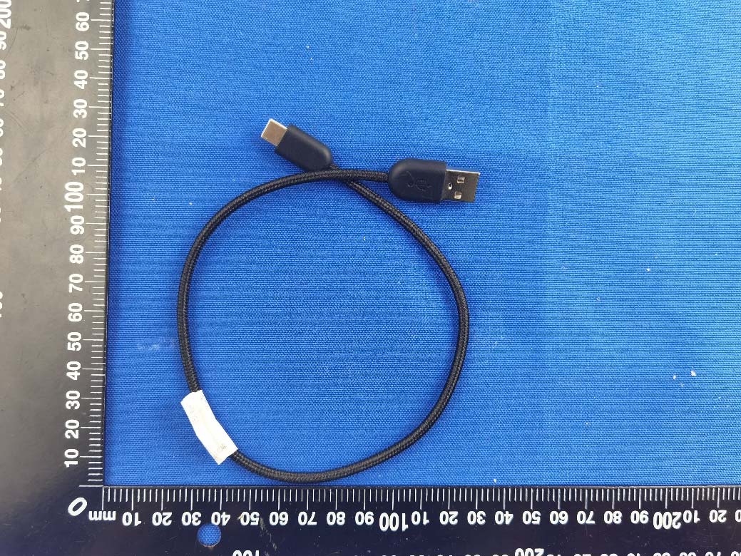
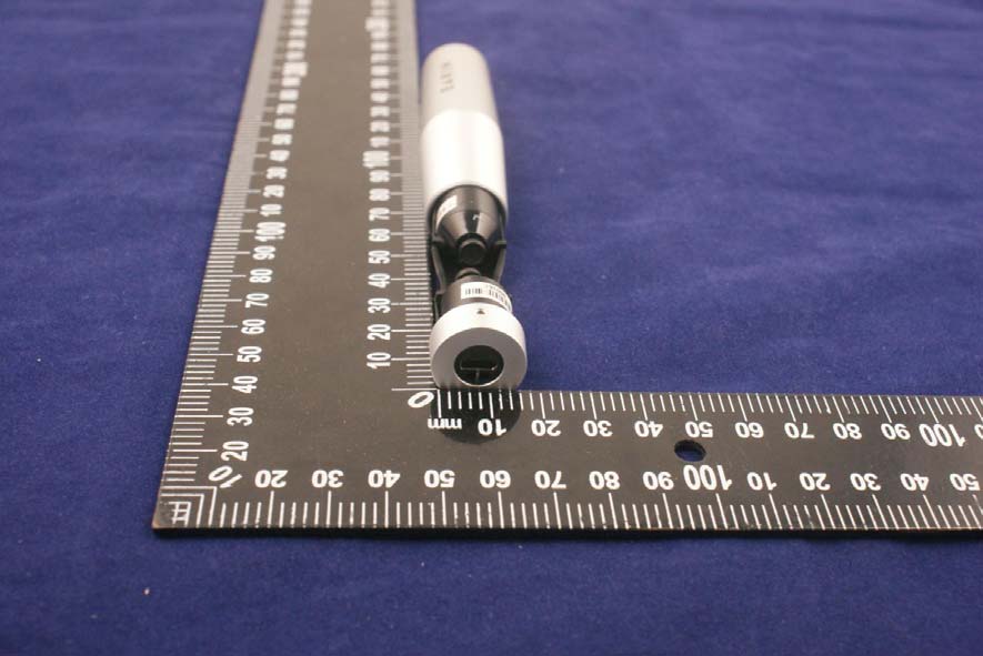
Annex No.:BL-SZ1590152-AW EXTERNALEUTPHOTOS CHARGER PHOTO 1 CHARGER PHOTO 2 Annex No.:BL-SZ1590152-AW 2 / 5 CHARGER PHOTO 3 CHARGER PHOTO 4 Annex No.:BL-SZ1590152-AW 3 / 5 THE FRONT OF EUT THEBACKOFEUT Annex No.:BL-SZ1590152-AW 4 / 5 THE LEFT OF EUT THE RIGHT OF EUT Annex No.:BL-SZ1590152-AW 5 / 5 THE UP OF EUT THE DOWN OF EUT

ID Label/Location Info

FCC ID: 2AEI2EARIN FCC ID Placement Earin, Olle Lindén 2015-08-18 www.earin.com 1(1) FCC ID placement. Earin here by submits justification for placing the FCC ID in the Associated User Manual. According to the FCC Regulation and Guidance ( KDB Publication 784748 D01, Section 2.2) allows for the FCC identifier to be moved to the User’s manual in the event that “the device is unquestionably too small for the FCC ID to be readable (smaller than 4-6 points)”. Referring to the above quote, the size of a readable FCC ID to be printed onto the Earin Earbuds would be equal to 1.4x21mm. A. Printing onto the front cover (A): The small size cylindrical, cone shape of the front cover does not provide enough physical space to fit the printing of the FCC ID according to below reference picture. B. Side surface: The cylindrical ribbon shape of the back cover (B) is not possible to print with a visibly acceptable result as the top surface of each rib is 0.4mm in width. C. Back edge: The curvature of the circular ring (C ) surrounding the connection PCB (D) makes the printing area too narrow to fit the height and length of the FCC ID. D. Connection PCB (D): The gold plated Earin Logo on the connection PCB act as contact interface during charging in the Earin capsule. The area outside the gold plating does not provide enough space for the required printing. Conclusion: Based on the above description of area A to D , we conclude that the device is unquestionably too small for enabling the FCC ID to be printed onto any surface. We therefore request to have the FCC ID moved to the User Guide. Best regards Olle Lindén Co-Founder, Earin

Internal Photos

Annex No.:BL-SZ1580152-AI EUT INTERNAL PHOTOS EUT Photo 1 EUT Photo 2 Annex No.:BL-SZ1580044-AI 2 / 5 EUT Photo 3 EUT Photo 4 Annex No.:BL-SZ1580044-AI 3 / 5 EUT Photo 5 EUT Photo 6 PIFA Antenna RF Chip Annex No.:BL-SZ1580044-AI 4 / 5 EUT Photo 7 EUT Photo 8 Annex No.:BL-SZ1580044-AI 5 / 5 Battery

RF Exposure Info

4 RF Exposure Evaluation for FCC ID: 2AEI2EARIN Refer user manual this device is a PORTABLE Legacy Wireless Bluetooth Headphones, and this device was designed used in portable devices that the minimum distance between human’s body is 5mm. Based on the 47CFR 2.1093, this device belongs to portable device. The definition of the category as following: Portable Derives: CFR Title 47 §2.1093(b) (b) For purposes of this section, a portable device is defined as a transmitting device designed to be used so that the radiating structure(s) of the device is/are within 20 centimeters of the body of the user. FCC KDB 447498 D01 General RF Exposure Guidance v05r02 Limit Unless specifically required by the published RF exposure KDB procedures, standalone 1-g head or body and 10-g extremity SAR evaluation for general population exposure conditions, by measurement or numerical simulation, is not required when the corresponding SAR Test Exclusion Threshold condition, listed below, is satisfied. These test exclusion conditions are based on source-based time-averaged maximum conducted output power of the RF channel requiring evaluation, adjusted for tune-up tolerance, and the minimum test separation distance required for the exposure conditions. The minimum test separation distance is determined by the smallest distance from the antenna and radiating structures or outer surface of the device, according to the host form factor, exposure conditions and platform requirements, to any part of the body or extremity of a user or bystander. The 1-g and 10-g SAR test exclusion thresholds for 100 MHz to 6 GHz at test separation distances ≤ 50 mm are determined by: [ (max.power of channel,including tune−up tolerance,mW) (min.test separation distance,mm) ] · [ √ f (GHz) ] ≤ 3.0 for 1-g SAR and ≤ 7.5 for 10-g extremity SAR Where • f (GHz) is the RF channel transmit frequency in GHz • Power and distance are rounded to the nearest mW and mm before calculation • The result is rounded to one decimal place for comparison The test exclusions are applicable only when the minimum test separation distance is ≤ 50 mm and for transmission frequencies between 100 MHz and 6 GHz. When the minimum test separation distance is < 5 mm, a distance of 5 mm is applied to determine SAR test exclusion. FCC exclusion condition= [ (6.90, mW) (5, mm) ] · [ √ 2. (GHz) ] = 2.173 < 3.0 RF Exposure Evaluation Result: Pass Note: More power data, Please refer to the RF report. 80

Test Report

R eport No.: BL-SZ1590152-601 2 Revision History V ersion I ssue Date R evisions R ev. 01 O ct. 10, 2015 I nitial Issue R ev. 02 O ct. 23, 2015 T he Second Issue TABLE OF CONTENTS TABLE OF CONTENTS .................................................................................................................................................. 2 1 ADMINISTRATIVE DATA(GENERAL INFORMATION) ......................................................................................... 6 1.1 Identification of the Testing Laboratory .............................................................................................................. 6 1.2 Identification of the Responsible Testing Location...........................................................................................6 1.3 Laboratory Condition.............................................................................................................................................6 1.4Announce................................................................................................................................................................6 2 PRODUCT INFORMATION.........................................................................................................................................8 2.1Applicant Information ............................................................................................................................................ 8 2.2 Manufacturer Information.....................................................................................................................................8 2.3 Factory Information...............................................................................................................................................8 2.4 General Description for Equipment under Test (EUT).....................................................................................8 2.5Ancillary Equipment...............................................................................................................................................8 2.6 Technical Information ............................................................................................................................................ 9 3 SUMMARY OF TEST RESULTS ............................................................................................................................. 10 3.1 Test Standards.....................................................................................................................................................10 3.2 Verdict ................................................................................................................................................................... 10 4 GENERAL TEST CONFIGURATIONS....................................................................................................................11 4.1 Test Environments...............................................................................................................................................11 4.2 Test Equipment List ............................................................................................................................................. 11 4.3 Test Configurations ............................................................................................................................................. 12 4.4 Description of Test Setup ................................................................................................................................... 12 4.4.1 For Antenna Port Test..................................................................................................................................12 4.4.2 For AC Power Supply Port Test.................................................................................................................13 4.4.3 For Radiated Test (Below 30 MHz)...........................................................................................................13 4.4.4 For Radiated Test (30 MHz-1 GHz) .......................................................................................................... 14 R eport No.: BL-SZ1590152-601 3 4. 4.5 For Radiated Test (Above 1 GHz).............................................................................................................14 4.5 Test Conditions....................................................................................................................................................15 4.6 Measurement Results Explanation Example .................................................................................................. 16 4.6.1 For conducted test items: ........................................................................................................................... 16 4.6.2 For radiated band edges and spurious emission test:...........................................................................16 5 TEST ITEMS...............................................................................................................................................................17 5.1Antenna Requirements.......................................................................................................................................17 5.1.1 StandardApplicable.....................................................................................................................................17 5.1.2AntennaAnti-Replacement Construction ................................................................................................. 17 5.1.3Antenna Gain ................................................................................................................................................ 17 5.2 Number of Hopping Frequency.........................................................................................................................18 5.2.1 Limit.............................................…

Text truncated - open the document above for the full version.

Test Setup Photos

Annex No.:BL-SZ1590152-AR TEST SETUP PHOTOS 1Radiated Field Emission Below 30MHz 30 MHz-1 GHz Annex No.:BL-SZ1590152-AR Above 1GHz 2Conducted Test Photo Annex No.:BL-SZ1590152-AR 3Conducted Emission

Contact Information

Applicant

KIRIL TRAJKOVSKI
[email protected]0046 760 195392Fax: 046-12 98 79

Test Firm

Shenzhen BALUN Technology Co.,Ltd.Xuewen Wu
[email protected]86-755-66833404Fax: 86-755-61824271

Technical Specifications

#Rule PartsFrequency RangePower Output
115C2.40 GHz - 2.48 GHz6.90 mW
Confidentiality
Long Term
Grant Notes
Power listed is conducted.

Other Applications from EARIN AB

EARIN A-3 - FCC ID 2AEI2EARINA3 - EARIN AB
2AEI2EARINA3

EARIN A-3

Nov 19, 2020

Equipment Class

DTS - Digital Transmission System