FCCID.CO- FCC ID Database
HomeCompaniesEquipment ClassesSearch

© 2026 FCC ID Database. All rights reserved.

AboutContactData sourced from FCC public records
  1. Home/
  2. EARIN AB/
  3. 2AEI2EARINA3

2AEI2EARINA3EARIN A-3

EARIN AB
EARIN A-3 - FCC ID 2AEI2EARINA3 - EARIN AB
Click to zoom

Application Details

Equipment Class
DTS - Digital Transmission System
Date of Grant
Nov 19, 2020
Application Purpose
Original Equipment
Date of Application
Nov 17, 2020
Equipment Note
EARIN A-3
Frequency Range
2402.00000000 - 2480.00000000
Company
EARIN AB
Country
Sweden

Documents & Files

Select a file to view

Users Manual

↗

Cover Letter(s)

↗
↗

External Photos

↗

ID Label/Location Info

↗

Internal Photos

↗

RF Exposure Info

↗

Test Report

↗

Test Setup Photos

↗

Document Text

Text extracted from the exhibit documents filed with the FCC. Open a document above to read the original.

Users Manual

USER GUIDE A – 3 DESIGNED & ENGINEERED IN SWEDEN Bluetooth Bluetooth Earin A–3 Bluetooth Pairing Request Cancel PAIR A B 2 secs 132 4 GET STARTEDGET STARTED Pour démarrer / Erste Schritte / PreparaciónPour démarrer / Erste Schritte / Preparación Activate Bluetooth on your device Activez Bluetooth sur votre appareil Aktivieren Sie Bluetooth auf Ihrem Gerät Activa la función Bluetooth en tu dispositivo Put both earphones in the case Mettez les deux écouteurs dans le boîtier de recharge Setzen Sie beide Ohrhörer in das Case Coloca ambos auriculares en el estuche Open case, press button 2 seconds for pairing mode, LED turns blue Ouvrez le boîtier, appuyez sur le bouton 2 secondes pour le mode de couplage, la LED devient bleue Gehäuse öffnen, Taste 2 Sekunden lang für den Kopplungsmodus drücken. Die LED leuchtet blau Abra la caja, pulse el botón 2 segundos para el modo de emparejamiento y el LED se volverá azul A. Pair with Earin A–3 B. Accept the following pairing request A. Appairer avec Earin A–3 B. Acceptez la demande d’appairage suivante A. Mit Earin A–3 koppeln B. Akzeptieren Sie die folgende Kopplungsanfrage A. Vincular con Earin A–3 B. Aceptar la siguiente solicitud de emparejamiento Charge case with USB-C cable or wireless charger Boîtier de charge avec câble USB-C ou chargeur sans fil Laden Sie das Case mit einem USB-C-Kabel oder dem Wireless-Ladegerät Estuche de carga con cable USB-C o cargador inalámbrico Put earphones in case to charge automatically Mettez les écouteurs dans le boîtier pour un chargement automatiquement Setzen Sie beide Ohrhörer in das Case um sie automatisch zu laden Coloca los auriculares en el estuche para que se carguen automáticamente Charging Recharge Wird geladen Cargando Charged Chargé Geladen Cargada Light position Position de la lumière Lichtposition Posición de la luz 80-100% 20-80% 0-20% BATTERY STATUS État de la batterie / Batteriestatus / Estado de la batería CHARGING Mise en charge / Ladevorgang / Carga Control Settings CONTROL Contrôles / Steuerung / Controles CONTROL Contrôles / Steuerung / Controles Remove earphone to auto-pause Re-insert to resume Retirez l’écouteur pour mettre en pause automatique Réinsérez pour reprendre Kopfhörer entfernen, um automatisch anzuhalten Zum Fortsetzen erneut einfügen Quítese el auricular para hacer una pausa automática Vuelva a insertarlo para reanudar Customize control with the “Earin” app Personnalisez les contrôles avec l’application Earin Steuerung über Earin App anpassen Personaliza los controles con la app Earin Long press here to activate voice assistant Appuyez longuement ici pour activer l’assistant vocal Lange drücken, um den Sprachassistenten zu aktivieren Realice una pulsación larga aquí para activar el asistente de voz Double tap earphone Play/pause & answer/hang up call Appuyez deux fois sur les écouteurs Lecture/Pause, réspondre à un appel ou raccrocher Doppeltippen Sie auf den Ohrhörer Wiedergabe/Pause, Anruf entgegennehmen oder auflegen Doble toque en el auricular Reproducir/Pausar, responder a una llamada o colgar UPDATE IN PROGESS You can continue using your earphones as usual during the update Automatic left/right ear detection Détection automatique gauche / droite Automatische Links-/Rechts-Erkennung Detección automática de izquierdo/derecho How to wear Comment porter les écouteurs So werden sie getragen Cómo llevar los auriculares APP Apple and the Apple logo are trademarks of Apple Inc., registered in the U.S. and other countries. App Store is a service mark of Apple Inc., registered in the U.S. and other countries. Google Play and the Google Play logo are trademarks of Google Inc. USAGE Usage / Nutzung / Modo de uso Download the “Earin” app for more features Téléchargez l’application “Earin” pour plus de fonctionnalités Laden Sie die “Earin” app herunter, um weitere Features nutzen zu können Descarga la app “Earin” para obtener más características ENGLISH FOR US AND CANADA FCC AND IC STATEMENT This device complies with part 15 of the FCC rules and Industry Canada license-exempt RSS standards. Operation is subject to the following two conditions: (1) this device may not cause harmful interference, and (2) this device must accept any interference received, including interference that may cause undesired operation. The SAR limit of IC is 1.6W/Kg for head. The highest SAR value reported under this standard during product certification when used against the head is 0.038W/Kg. FCC ID: 2AEI2EARINA3 / IC: 20729-EARINA3 CAN FCC/IC RADIATION EXPOSURE STATEMENT This equipment complies with FCC/IC RSS-102 radiation exposure limits set for an uncontrolled environment. NOTE: This equipment has been tested and found to comply with the limits for a Class B digital device, pursuant to part 15 of the FCC Rules. These limits are designed to provide reasonable protection against harmful interference in a residential installation. This equipment generates, uses and can radiate radio frequency energy and, if not installed and used in accordance with the instructions, may cause harmful interference to radio communications. However, there is no guarantee that interference will not occur in a particular installation. If this equipment does cause harmful interference to radio or television reception, which can be determined by turning the equipment off and on, the user is encouraged to try to correct the interference by one or more of the following measures: • Reorient or relocate the receiving antenna. • Increase the seperation between the equipment and receiver. • Connect the equipment into an outlet on a circuit different from that to which the receiver is connected. • Consult the dealer or an experienced radio/TV technician for help. FCC Caution: The manufacturer is not responsible for any changes or modifications not expressly approved by the party responsible for compliance. Such modifications could void the user’s authority to operate the equipment. FOR EUROPEAN COUNTRIES WEEE NOTICE The purpose of the Dire…

Text truncated - open the document above for the full version.

External Photos

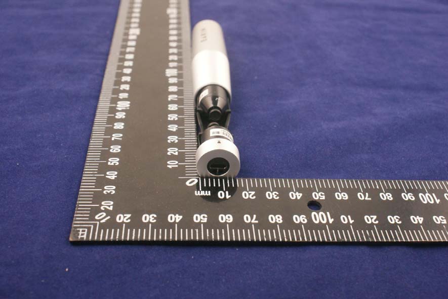
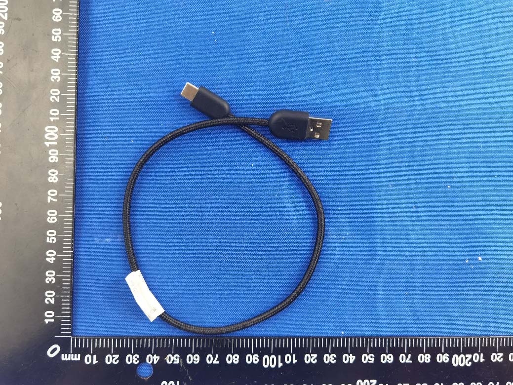
Annex No.: BL-SZ2080448-AW 1 / 4 EUT EXTERNAL PHOTOS FRONT VIEW OF EUT REAR VIEW OF EUT Annex No.: BL-SZ2080448-AW 2 / 4 LEFT SIDE VIEW OF EUT RIGHT SIDE OF EUT Annex No.: BL-SZ2080448-AW 3 / 4 TOP VIEW OF EUT BOTTOM VIEW OF EUT Annex No.: BL-SZ2080448-AW 4 / 4 Accessory-Charging Case Accessory-USB Cable

ID Label/Location Info

Label&location: FCC ID:2AEI2EARINA3 Location: The device is too small to display FCC ID. FCC ID will displayed on user manual.

Internal Photos

Annex No.: BL-SZ2080448-AI 1 / 4 EUT INTERNAL PHOTOS EUT UNCOVER VIEW EUT UNCOVER VIEW FPC Antenna Annex No.: BL-SZ2080448-AI 2 / 4 MAIN BOARD TOP VIEW (WITH SHIELDING) MAIN BOARD TOP VIEW (WITHOUT SHIELDING) RF Chip Annex No.: BL-SZ2080448-AI 3 / 4 MAIN BOARD REAR VIEW Battery Photo (FRONT) Annex No.: BL-SZ2080448-AI 4 / 4 Battery Photo (REAR)

RF Exposure Info

RF Exposure Evaluation for FCC ID: 2AEI2EARINA3 Refer user manual this device is a EARIN A-3, and this device was designed used in portable devices that the minimum distance between human’s body is 5mm. Based on the 47CFR 2.1093, this device belongs to portable device. The definition of the category as following: Portable Derives: CFR Title 47 §2.1093(b) (b) For purposes of this section, a portable device is defined as a transmitting device designed to be used so that the radiating structure(s) of the device is/are within 20 centimeters of the body of the user. FCC KDB 447498 D01 General RF Exposure Guidance v06 Limit Unless specifically required by the published RF exposure KDB procedures, standalone 1-g head or body and 10-g extremity SAR evaluation for general population exposure conditions, by measurement or numerical simulation, is not required when the corresponding SAR Test Exclusion Threshold condition, listed below, is satisfied. These test exclusion conditions are based on source- based time-averaged maximum conducted output power of the RF channel requiring evaluation, adjusted for tune-up tolerance, and the minimum test separation distance required for the exposure conditions. The minimum test separation distance is determined by the smallest distance from the antenna and radiating structures or outer surface of the device, according to the host form factor, exposure conditions and platform requirements, to any part of the body or extremity of a user or bystander. The 1-g and 10-g SAR test exclusion thresholds for 100 MHz to 6 GHz at test separation distances ≤ 50 mm are determined by: [(max. power of channel, including tune-up tolerance, mW) / (min. test separation distance, mm)] · [√f(GHz) ] ≤ 3.0 for 1-g SAR and ≤ 7.5 for 10-g extremity SAR Where • f (GHz) is the RF channel transmit frequency in GHz • Power and distance are rounded to the nearest mW and mm before calculation • The result is rounded to one decimal place for comparison The test exclusions are applicable only when the minimum test separation distance is ≤ 50 mm and for transmission frequencies between 100 MHz and 6 GHz. When the minimum test separation distance is < 5 mm, a distance of 5 mm is applied to determine SAR test exclusion. Test data Bluetooth Mode BR+EDR BLE 1Mbps BLE 2Mbps GFSK ∏/4-DQPSK 8-DPSK GFSK GFSK Peak Power (dBm) 9.12 8.33 9.11 5.88 6.43 Note: This report listed the worst case peak power value, please refer to RF test report for more details. Turn-up power Mode Range (dBm) Bluetooth BR+EDR 8.00-9.50 BLE 5.50-7.00 FCC exclusion condition= [8.91 mW/5 mm] · [√2.48 GHz] = 2.8 < 3.0 RF Exposure Evaluation Result: Pass Note: More power data, Please refer to the RF report.

Test Report

Report No.: BL-SZ2080448-602 2 / 67 Revision History VersionIssue DateRevisions Content Rev. 01Nov. 11, 2020Initial Issue TABLE OF CONTENTS 1 ADMINISTRATIVE DATA (GENERAL INFORMATION) ................................................................................... 5 1.1Identification of the Testing Laboratory.................................................................................................5 1.2Identification of the Responsible Testing Location .............................................................................. 5 1.3Lab Conditions ........................................................................................................................................... 5 1.4Notice..........................................................................................................................................................5 2 PRODUCT INFORMATION...................................................................................................................................6 2.1Applicant Information................................................................................................................................6 2.2Manufacturer Information.........................................................................................................................6 2.3Factory Information ................................................................................................................................... 6 2.4General Description for Equipment under Test (EUT)........................................................................6 2.5Technical Information ............................................................................................................................... 6 2.6Additional Instructions..............................................................................................................................7 3 SUMMARY OF TEST RESULTS..........................................................................................................................8 3.1Test Standards .......................................................................................................................................... 8 3.2Verdict ......................................................................................................................................................... 8 4 GENERAL TEST CONFIGURATIONS .............................................................................................................. 10 4.1Test Environments .................................................................................................................................. 10 4.2Test Equipment List................................................................................................................................10 4.3Measurement Uncertainty.....................................................................................................................11 4.4Description of Test Setup ...................................................................................................................... 12 4.4.1 For Antenna Port Test............................................................................................................................12 4.4.2 For AC Power Supply Port Test ........................................................................................................... 12 4.4.3 For Radiated Test (Below 30 MHz)......................................................................................................13 4.4.4 For Radiated Test (30 MHz-1 GHz).....................................................................................................13 4.4.5 For Radiated Test (Above 1 GHz)........................................................................................................14 4.5Measurement Results Explanation Example.....................................................................................15 4.5.1 For conducted test items: ...................................................................................................................... 15 Report No.: BL-SZ2080448-602 3 / 67 4.5.2 For radiated band edges and spurious emission test: ...................................................................... 15 5 TEST ITEMS..........................................................................................................................................................16 5.1Antenna Requirements .......................................................................................................................... 16 5.1.1 Relevant Standards ................................................................................................................................ 16 5.1.2 Antenna Anti-Replacement Construction............................................................................................16 5.1.3 Antenna Gain...........................................................................................................................................16 5.2Output Power...........................................................................................................................................17 5.2.1 Test Limit..................................................................................................................................................17 5.2.2 Test Setup ................................................................................................................................................ 17 5.2.3 Test Procedure........................................................................................................................................17 5.2.4 Test Result...............................................................................................................................................18 5.3Occupied Bandwidth...................................................................…

Text truncated - open the document above for the full version.

Test Setup Photos

Annex No.: BL-SZ2080448-AR 1 / 5 TEST SETUP PHOTOS 1 Radiated Test Photo Below 30MHz 30MHz-1GHz Annex No.: BL-SZ2080448-AR 2 / 5 Close-up Above 1GHz Annex No.: BL-SZ2080448-AR 3 / 5 Close-up 2 Conducted Test Photo Conducted Test-BT3.0 Annex No.: BL-SZ2080448-AR 4 / 5 Conducted Test-BLE 3 Conducted Emissions Test Photo 1 Annex No.: BL-SZ2080448-AR 5 / 5 Test Photo 2

Contact Information

Applicant

KIRIL TRAJKOVSKI
[email protected]0046 760 195392Fax: 046-12 98 79

Technical Contact

Shenzhen BALUN Technology Co., Ltdxuewen wu
[email protected]86-755-66833404

Block B, FL 1, Baisha Science and Technology Park, · China

Non-Technical Contact

Shenzhen BALUN Technology Co., LtdTiffany Zhang
[email protected]86-755-66850100

Test Firm

Shenzhen BALUN Technology Co., Ltd.Hanson Lin
[email protected]86-755-66833830

Technical Specifications

#Rule PartsFrequency RangePower Output
115C2.40 GHz - 2.48 GHz4.40 mW
Confidentiality
Long Term
Grant Notes
Power Output is conducted. This is a portable device. The antenna(s) used for this transmitter must not be co-located or operating in conjunction with any other antenna or transmitter. End users must be provided with specific operating instructions for satisfying RF exposure compliance.

Other Applications from EARIN AB

EARIN - FCC ID 2AEI2EARIN - EARIN AB
2AEI2EARIN

EARIN

Oct 26, 2015

Equipment Class

DSS - Part 15 Spread Spectrum Transmitter