2AEI3-HB01-HL01A Battery Powered RFID Smart Lock
WaveLynx Technologies LLC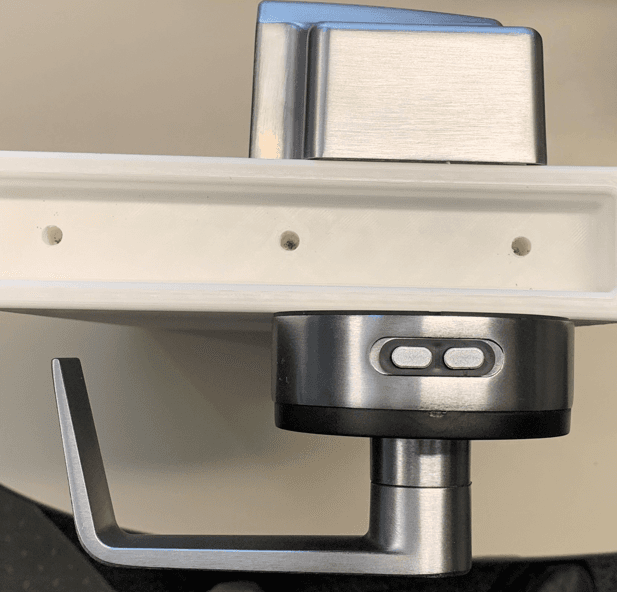
Click to zoom
Application Details
- Equipment Class
- DXX - Part 15 Low Power Communication Device Transmitter
- Date of Grant
- Jan 23, 2023
- Application Purpose
- Original Equipment
- Date of Application
- Jan 19, 2023
- Equipment Note
- A Battery Powered RFID Smart Lock
- Frequency Range
- 13.56000000 - 13.56000000
- Company
- WaveLynx Technologies LLC
- Country
- United States
Documents & Files
Document Text
Text extracted from the exhibit documents filed with the FCC. Open a document above to read the original.
Users Manual
EQ45 GRADE 1 EXIT TRIM INSTALLATION INSTRUCTIONS I-ED02734 Rev 1, Rev Date: 01/12/2023 [27390110] Page 1 of 8 Hager Companies 139 Victor Street, St. Louis, MO 63104 (800) 325-9995 www.hagerco.com Part Description QTY 1 Exit Trim Assembly 1 2 Screw Pack, 4500 Trim 1 AA Handing Pin 1 BB Screw, 1/4”-20 x 3/4” Pan Head Combo Drive Machine 4 CC Screw, 1/4”-20 x 1.25” Pan Head Combo Drive Machine 4 3 Power Pack Assy 1 4 AA Batteries 4 5 Screw Pack, Power Pack, Exit Trim 1 Screw, #12 x 3/4” Pan Head Phillips Drive Sheet Metal 1 6 Main Gasket 1 7 Wire Harness, Control to Reader Board 1 8 Instruction Sheets 1 9 Template 1 8 9 RIM specific Instructions Page4 SVR specific Instructions Page 5-6 Part Description QTY 10 SVR Spacer Block, Power Pack 1 11 6 Wire Extension 1 12 2 Wire Extension 1 13 8 Wire Extension 1 14 Power Pack to SVR Block Screws 1 EE Screws, #12 x 1/2” Thread Forming 4 SVR Block Kit Required to install battery pack for SVR exit devices AA BB DD CC EE EQ45 GRADE 1 EXIT TRIM INSTALLATION INSTRUCTIONS I-ED02734 Rev 1, Rev Date: 01/12/2023 [27390110] Page 2 of 8 Hager Companies 139 Victor Street, St. Louis, MO 63104 (800) 325-9995 www.hagerco.com 1 Safety Information Carefully read the instructions before installing and using this lock. WARNING: If the door needs to be drilled, be familiar with how to safely use your tools, and understand all the door preparation steps before proceeding. FINISH & CARE NOTES: Either remove the locks or do not install them prior to painting your door to protect the finish. Periodically clean the locks with mild soap and a soft cloth. Do not use abrasives or harsh chemicals when cleaning or using the lock. Required Tools 2 T10 PH2 PH3 OPTIONAL OPTIONAL 3 Prepare Door Skip the prep steps if the door has already been prepared. 1 NOTE: Drill from both sides to avoid splintering the finished surface of wood doors. Not all holes are thru. AA Mark the Horizontal Centerline and Vertical Centerline on the door face based on the exit device installation instructions. Align the template and mark the door, drill the holes per template instructions. 4 Remove back plate from Exit Escutcheon Prepare Exit Escutcheon 1 Hand Escutcheon • Unstow the wires. • Remove spring cage if necessary to orient arrows to match downward motion of the lever. Reattach with screws provided. • Orient lever to desired handing. RHR shown, LHR opposite side of escutcheon • Insert handing pin AA as shown. 2 EQ45 GRADE 1 EXIT TRIM INSTALLATION INSTRUCTIONS I-ED02734 Rev 1, Rev Date: 01/12/2023 [27390110] Page 3 of 8 Hager Companies 139 Victor Street, St. Louis, MO 63104 (800) 325-9995 www.hagerco.com 4 Plug in the Wire Harness #7 into the Reader Board as shown. Prepare Exit Escutcheon, Continued 3 Close up escutcheon and install Main Gasket. • Route wires through wiring hole shown • Install Main Gasket #6 4 7 6 Adjust Telescopic Actuating Shaft for Door Thickness • The shaft clicks into place and is adjustable to the follow- ing door thicknesses: • 1-3/4” [44.5] (As shipped) • 2” [50.8] • 2-1/4” [57.2] • 2-1/2” [63.5] • 3” [76.2] 5 EQ45 GRADE 1 EXIT TRIM INSTALLATION INSTRUCTIONS I-ED02734 Rev 1, Rev Date: 01/12/2023 [27390110] Page 4 of 8 Hager Companies 139 Victor Street, St. Louis, MO 63104 (800) 325-9995 www.hagerco.com • Install exit trim onto the exterior side of the door routing the 2 Pin black wire into the lower wiring hole and the rest of the wires into the upper wiring hole as shown. • Install the SVR exit device head onto the interior side of the door using the (4) BB screws (1/4”-20 x 3/4”) provided and route the 2 Pin wire with black shrink wrap through the hole shown. BB 1 5 Install Exit Trim and Power Pack, RIM Black 2 Pin All Other Wires Wire Hole • Remove the cover of Power Pack #3 • Install Power Pack #3 using (4) DD screws (#12 x 3/4”) provided. Be sure to route the remaining wires through the lower power pack wiring hole. 2 DD 3 Lower Wiring Hole CONNECT READER AND EXIT DEVICE • Plug in the Reader (6 pin), 9V power (2 pin), and Exit Trim and Device (8 pin) wire harnesses as shown above. • Plug in the 2 Pin plug with the black shrink wrap to the RX wire in the RIM head as shown below. 3 EQ45 GRADE 1 EXIT TRIM INSTALLATION INSTRUCTIONS I-ED02734 Rev 1, Rev Date: 01/12/2023 [27390110] Page 5 of 8 Hager Companies 139 Victor Street, St. Louis, MO 63104 (800) 325-9995 www.hagerco.com 6 • Install exit trim onto the exterior side of the door routing the 2 Pin black wire into the lower wiring hole and the rest of the wires into the upper wiring hole as shown. • Install the SVR exit device head onto the interior side of the door using the (4) BB screws (1/4”-20 x 3/4”) provided and route the 2 Pin wire with black shrink wrap through the hole shown. Install Exit Trim and Power Pack, SVR 1 • Plug the 2, 6, and 8 Pin Extension harnesses #11, 12, & 13 into their respective wires in the upper wire bundles. • Route the extension wires through the lower half of the SVR Spacer Block #10 until about 3” (3.5”?) are sticking out of the block. Stow the remainder under the block. • Mount the SVR block #10 to the door using (4) EE screws. 2 BB Wire Hole Black 2 Pin All Other Wires DD 11, 12, 13 10 8 Pin 6 Pin EE 3 Lower Wiring Hole • Plug in the Reader (6 pin), 9V power (2 pin), and Exit Trim and Device (8 pin) wire harnesses as shown below. • Plug in the 2 Pin plug with the black shrink wrap to the RX wire in the SVR head as shown below. 3 SVR RX Plugs EQ45 GRADE 1 EXIT TRIM INSTALLATION INSTRUCTIONS I-ED02734 Rev 1, Rev Date: 01/12/2023 [27390110] Page 6 of 8 Hager Companies 139 Victor Street, St. Louis, MO 63104 (800) 325-9995 www.hagerco.com 7 INSTALL 4 AA BATTERIES Install the 4 AA batteries in the battery holder. Follow batterie orientation notes in the holder. • What happens when batteries installed? Lights? Sounds Setup Trim 1 SETUP LOCK • Setup procedure • 2 COMMISSION LOCK • GO TO COMMISSIONING PROCEDURE • GIVE QR CODE 3 SHOW SELECTION OF OTHER PRODUCTS THAT CAN BE USED WITH THIS LOCK HU…
Text truncated - open the document above for the full version.
Users Manual
EQ34 GRADE 1 CYLINDRICAL LOCK INSTALLATION INSTRUCTIONS I-LS02688 Rev 1, Rev Date: 01/12/2023 [27390107] Page 1 of 7 Hager Companies 139 Victor Street, St. Louis, MO 63104 (800) 325-9995 www.hagerco.com Part Description QTY 1 ASA Strike 1 2 Rose, Cylindrical 1 3 Spring Cage Assembly, Interior 1 4 Lock Chassis Assembly 1 5 Interior Mounting Plate with RX Switch 1 6 Spring Cage Assembly, Exterior 1 7 Withnell Lever, Interior 1 8 Withnell Lever, Exterior, NKO 1 9 Mounting Bracket, Exterior 1 10 Dead Latch 1 11 Screw Pack, EQ34 1 AA Allen Wrench, 3/32” 1 BB Lever Removal Tool 1 CC Screw, #10-32 x 1.4” Oval Head Machine 4 DD Screw, #12-24 X 3/4” Flat Head Combo 2 EE Screw, #8-32 x 3/4” Flat Head Combo 2 12 Set Screw, #10-32 x 1/4”, 3/32” Drive 2 13 Retaining Plate, Lever 2 14 AA Alkaline Batteries 4 15 Escutcheon Assembly, Cylindrical 1 16 Power Pack Assembly 1 17 Screw Pack, Power Pack 1 FF Screw, #12 x ¾” Pan Head 2 GG Screw, #10-32 x ¾” Pan Head Machine 1 HH Hex Standoff, #10-32 x 1.5” Male-Female 1 18 Wiring Harness, Control Board to Reader 1 19 Wiring Harness, Control Board to Lock 1 20 Main Gasket, Cylindrical 1 21 Tailpiece (Key Override Only) 1 22 Cup (Key Override Only) 23 Installation Instructions 24 Template 1 25 Door Thickness Guide 1 AA BB CC DD FF EE GG HH 23 24 25 EQ34 GRADE 1 CYLINDRICAL LOCK INSTALLATION INSTRUCTIONS I-LS02688 Rev 1, Rev Date: 01/12/2023 [27390107] Page 2 of 7 Hager Companies 139 Victor Street, St. Louis, MO 63104 (800) 325-9995 www.hagerco.com 1 Safety Information Carefully read the instructions before installing and using this lock. WARNING: If the door needs to be drilled, be familiar with how to safely use your tools, and understand all the door preparation steps before proceeding. FINISH & CARE NOTES: Either remove the locks or do not install them prior to painting your door to protect the finish. Periodically clean the locks with mild soap and a soft cloth. Do not use abrasives or harsh chemicals when cleaning or using the lock. Required Tools 2 T10 PH2 PH3 OPTIONAL OPTIONAL OPTIONAL OPTIONAL 3 Prepare Door & Frame / Install Latch & Strike Skip the prep steps if the door has already been prepared. Just install the latch and strike as shown below. 1 NOTE: Drill from both sides to avoid splintering the finished surface of wood doors Distance from finished floor 2 10 Mark the Lever Centerline on the door face and edge at desired distance from the finished floor. Align the template and mark the door, drill the holes. Insert latch, trace around face plate and chisel out a mortise pocket. Use a Ø1/8” [3.2 mm] pilot holes for 2 EE screws. Install #10 latch using two #8 screws, EE. EE Drill x2 Chisel out Mark Jamb for strike as shown below. Drill two Ø1” [25.4 mm] holes 3/4” [19 mm] deep in the jamb 15/16” [8 mm] above and below the horizontal center line and then chisel out. NOTE: To ensure proper lockset function, the hole in the jamb must be drilled a full 3/4” [19 mm] deep. Mark jamb for strike and chisel out to a depth of 3/32” [2.4 mm] or until flush. Drill 2 pilot holes for #12 strike screws. Install #1 Strike with two #12 screws, DD. 2X PILOT HOLES Ø 3/16” DD 1 EQ34 GRADE 1 CYLINDRICAL LOCK INSTALLATION INSTRUCTIONS I-LS02688 Rev 1, Rev Date: 01/12/2023 [27390107] Page 3 of 7 Hager Companies 139 Victor Street, St. Louis, MO 63104 (800) 325-9995 www.hagerco.com Assemble chassis to spring cage assembly and route wire harness #19. • Verify the Retractor and Retaining Plate are facing the same direction. • Route Wire Harness #19 (lock to control board) as shown • Feed the (2) 2-pin plugs through spring cage assembly. In the back of the spring cage, through the hole behind the retractor as shown below. • Adjust harness to line up with the silver line with the face shown. This should be 3” [76 mm] from the end of the longest 2 pin plug. 4 Remove the lock chassis from the lever assembly and adjust for door thickness if necessary. • Note the thickness of the door. • If it is thicker than 1.75” [44.5 mm], then adjust the chassis assembly to the proper door thickness using the Door Thickness Guide included with the product. Prepare Lock Chassis 1 Remove the lever using the Allen wrench, AA. • Fully loosen set screw in the base of the lever shown below. Rotate CCW to loosen. • Then insert the end of the Allen wrench into a hole in the retaining plate below and pull back the plate to release the lever. Remove the lever and set aside. • KEY OVERRIDE ONLY! To remove the lever, insert lever removal tool BB and pull the lever off. Set the lever aside for later. 2 3 Retaining Plate Retractor Align line with plate 3” [76 mm] EQ34 GRADE 1 CYLINDRICAL LOCK INSTALLATION INSTRUCTIONS I-LS02688 Rev 1, Rev Date: 01/12/2023 [27390107] Page 4 of 7 Hager Companies 139 Victor Street, St. Louis, MO 63104 (800) 325-9995 www.hagerco.com 5 • Remove the back plate from the exterior escutcheon. • Note the handing of the door above and assemble the prepared Lock Chassis into the exterior escutcheon. • Route the wire harness along the side of the escutcheon and over to the center of the lock as shown. Prepare Exterior Escutcheon 1 INSIDE OUTSIDE INSIDE OUTSIDE INSIDE OUTSIDE INSIDE OUTSIDE RH—RIGHT HAND DOOR RHR—RIGHT HAND REVERSE DOOR LH—LEFT HAND DOOR LHR—LEFT HAND REVERSE DOOR DOOR HANDING Determine the handing of your door opening before preparing the exterior escutcheon. RH / RHR LH / LHR Wires Wires Retractors • Plug the 6-pin wire harness #18 into the reader board and re-install the back plate. 2 18 EQ34 GRADE 1 CYLINDRICAL LOCK INSTALLATION INSTRUCTIONS I-LS02688 Rev 1, Rev Date: 01/12/2023 [27390107] Page 5 of 7 Hager Companies 139 Victor Street, St. Louis, MO 63104 (800) 325-9995 www.hagerco.com 5 • Install Hex Standoff HH. • Install Main Gasket #20 onto the backplate centered on the escutcheon. • Plug 2-pin male wire harness into 2-pin female chassis wire. Prepare Exterior Escutcheon, Continued 3 HH 20 4 Install lever and tighten down the set screw. • Press lever onto spindle u…
Text truncated - open the document above for the full version.
Users Manual
EQ38E GRADE 1 ESCUTCHEON MORTISE LOCK INSTALLATION INSTRUCTIONS I-LS02690 Rev 1, Rev Date: 01/22/2023 [27390108] Page 1 of 7 Hager Companies 139 Victor Street, St. Louis, MO 63104 (800) 325-9995 www.hagerco.com Part Description QTY 1 Mortise Lock Body 1 2 Interior Lever 1 3 Spring Cage 2 4 Screw Pack, Lock 1 AA M4 X 40 mm Screws 2 BB Square Drive 2 CC Spring, Square Drive 2 DD Spanner Tool 1 5 Rose, Interior 1 6 Lever Mounting Plate, Interior 1 7 Armor Front with screws 1 EE M4 X 6 mm Flat Head Screw 2 8 Bearing, External Escutcheon 1 9 Strike with Screws 1 FF #12-24 x ¾” Flat Head Combo Screws 4 10 Cylinder Collar (Key Override Only) 1 11 Dust Box 1 12 Exterior Escutcheon 1 13 Screw Pack, Power Pack 1 GG Hex Standoff, #10-32 Female/Male 1 HH #12 x ¾” Pan Head Screw 2 II #10-32 x ¾” Pan Head Screw 1 14 AA Alkaline Batteries 4 15 Power Pack Assembly 1 16 Wiring Harness, Control Board to Reader 1 17 Main Gasket 1 18 DPS Magnetic Plate (DPS Only) 1 19 Installation Instructions 1 20 Template 1 AA BB CC EE DD DD FF GG II HH NOTE: Key Override Requires 1-5/8” or longer mortise cylinders 19 20 EQ38E GRADE 1 ESCUTCHEON MORTISE LOCK INSTALLATION INSTRUCTIONS I-LS02690 Rev 1, Rev Date: 01/22/2023 [27390108] Page 2 of 7 Hager Companies 139 Victor Street, St. Louis, MO 63104 (800) 325-9995 www.hagerco.com 1 Safety Information Carefully read the instructions before installing and using this lock. WARNING: If the door needs to be drilled, be familiar with how to safely use your tools, and understand all the door preparation steps before proceeding. FINISH & CARE NOTES: Either remove the locks or do not install them prior to painting your door to protect the finish. Periodically clean the locks with mild soap and a soft cloth. Do not use abrasives or harsh chemicals when cleaning or using the lock. Required Tools 2 T10 PH2 PH3 OPTIONAL OPTIONAL OPTIONAL OPTIONAL 3 Mark the Lever Centerline on the door face and edge at desired distance from the finished floor. Align the template and mark the door, drill the holes, and chisel out a mortise pocket. Use a Ø3/16” [4.8 mm] pilot hole for FF & HH screws. Mark the lock centerline from the template onto the door edge. Door / Frame Preparation (Skip this step if the door has already been prepared) 1 NOTE: Drill from both sides to avoid splintering the finished surface of wood doors Distance from finished floor 2 Prepare the door jamb for the strike. Mark the horizontal lock centerline from the door across the door jamb. Mark a line 3/8” above the lock centerline for the horizontal strike centerline. Mark the vertical centerline for the strike on the jamb. Align the template and mark holes. Drill 3/16” [4.8 mm] pilot holes for #12 strike screws. Drill Ø 1” holes for strike hole and chisel out pocket. Mark and chisel out jamb for strike plate until plate is flush. See template for dimensions. Suggested strike depths are shown below for a variety of features. ℄ Lock ℄ Strike ℄ Strike Ø 3/16” Ø 7/32” Hardwood Strike depth: • .143” Strike + DPS + Dust Box • .128” Strike + Dust Box • .093” Strike + DPS • .078” Strike Only Drill x3 Chissel out EQ38E GRADE 1 ESCUTCHEON MORTISE LOCK INSTALLATION INSTRUCTIONS I-LS02690 Rev 1, Rev Date: 01/22/2023 [27390108] Page 3 of 7 Hager Companies 139 Victor Street, St. Louis, MO 63104 (800) 325-9995 www.hagerco.com 4 Install the strike, DPS Plate (DPS feature only), and dust box (if needed) using (2) #12 screws FF. • DPS Plate is only needed with DPS function mortise locks • Dust box is only needed on jambs without built in dust boxes. Install Strike 1 5 Identify the handing of the opening (see above). Remove the handing screw of the outside side of the lock body. See above for desired bolt orientation and handing screw to remove for opening handing. To change the latch bolt, remove the Latch Screw, remove the latch and twist it around 180°. Insert the latch back into the lock body and re-install the Latch Screw as shown below. Hand Lock Body 1 INSIDE OUTSIDE INSIDE OUTSIDE INSIDE OUTSIDE INSIDE OUTSIDE RH—RIGHT HAND DOOR RHR—RIGHT HAND REVERSE DOOR LH—LEFT HAND DOOR LHR—LEFT HAND REVERSE DOOR Dust DPS Plate Strike RH—RIGHT HAND DOOR RHR—RIGHT HAND REVERSE DOOR LH—LEFT HAND DOOR LHR—LEFT HAND REVERSE DOOR INSIDE OUTSIDE INSIDE OUTSIDE INSIDE OUTSIDE INSIDE OUTSIDE Remove handing screw Remove handing screw Remove handing screw Remove handing screw Latch Screw Handing Screw Handing Screw 6 INSTALL LOCK BODY Route lock body wire harness into the lock prep and out the wiring hole as the body is inserted into the door as shown below. Fasten down using (2) #12 screws FF. DO NOT FULLY TIGHTEN. Install Lock on Door 1 FF TOP TOP TOP TOP TIP! If you have trouble routing the wire through the hole, try tying a string around the lock body wires below the plug. • Thread the string through the hole. • Gently pull the wire through with the string. Avoid applying force to the plug head. FF EQ38E GRADE 1 ESCUTCHEON MORTISE LOCK INSTALLATION INSTRUCTIONS I-LS02690 Rev 1, Rev Date: 01/22/2023 [27390108] Page 4 of 7 Hager Companies 139 Victor Street, St. Louis, MO 63104 (800) 325-9995 www.hagerco.com 6 PREPARE INTERIOR ROSE Unscrew interior lever and separate lever & rose from mounting plate Install Lock on Door (continued) 2 PREPARE EXTERIOR ESCUTCHEON • Remove the back plate from the exterior escutcheon. • Plug the reader wire harness #16 into reader board. Make sure the plug snaps into the header. • Re-install the back plate, routing the 2 pin and 6 pin connectors through the wiring hole. • Tighten 4 screws and install steel standoff GG. • Install main gasket #17 • Start #10-32 screw II into standoff GG (just a few turns) • Install lever bushing #8 as shown below • Orient spring cage #3 with arrows in the direction of lever rota- tion (down) and insert onto mounting posts as shown. 3 Match up direction of lever rotation downward to direction of the arrows on spring cage #3. Insert into mounting plate #6 and set aside with 2 mounting screws AA. AA 16 3…
Text truncated - open the document above for the full version.
Users Manual
EQ38S GRADE 1 SECTIONAL MORTISE LOCK INSTALLATION INSTRUCTIONS I-LS02692 Rev 1, Rev Date: 01/12/2023 [27390109] Page 1 of 7 Hager Companies 139 Victor Street, St. Louis, MO 63104 (800) 325-9995 www.hagerco.com Part Description QTY 1 Mortise Lock Body 1 2 Interior Lever 1 3 Spring Cage 2 4 Screw Pack, Lock 1 AA M4 X 40 mm Screws 2 BB Square Drive 2 CC Spring, Square Drive 2 DD Spanner Tool 1 5 Rose, Interior 1 6 Lever Mounting Plate, Interior 1 7 Armor Front with screws 1 EE M4 X 6 mm Flat Head Screw 2 8 Bearing, External Escutcheon 1 9 Strike with Screws 1 FF #12-24 x ¾” Flat Head Combo Screws 4 10 Cylinder Collar (Key Override Only) 1 11 Dust Box 1 12 Reader Escutcheon 1 13 Screw Pack, Power Pack 1 GG Hex Standoff, #10-32 Female/Male 3 HH #12 x ¾” Pan Head Screw 4 II #10-32 x ¾” Pan Head Screw 3 JJ Escutcheon Mounting Strap (Fire Doors) 1 14 AA Alkaline Batteries 4 15 Power Pack Assembly 1 16 Wiring Harness, Control Board to Reader 1 17 Main Gasket 1 18 Exterior Lever Assembly 1 19 Door Position Magnet (DPS Function Only!) 1 20 Installation Instructions 1 21 Template 1 AA BB CC EE DD FF GG II HH JJ 20 21 EQ38S GRADE 1 SECTIONAL MORTISE LOCK INSTALLATION INSTRUCTIONS I-LS02692 Rev 1, Rev Date: 01/12/2023 [27390109] Page 2 of 7 Hager Companies 139 Victor Street, St. Louis, MO 63104 (800) 325-9995 www.hagerco.com 1 Safety Information Carefully read the instructions before installing and using this lock. WARNING: If the door needs to be drilled, be familiar with how to safely use your tools, and understand all the door preparation steps before proceeding. FINISH & CARE NOTES: Either remove the locks or do not install them prior to painting your door to protect the finish. Periodically clean the locks with mild soap and a soft cloth. Do not use abrasives or harsh chemicals when cleaning or using the lock. Required Tools 2 T10 PH2 PH3 OPTIONAL OPTIONAL OPTIONAL OPTIONAL 3 Mark the Lever Centerline on the door face and edge at desired distance from the finished floor. Align the template and mark the door, drill the holes, and chisel out a mortise pocket. Use a Ø3/16” [4.8 mm] pilot hole for FF & HH screws. Mark the lock centerline from the template onto the door edge. Door / Frame Preparation (Skip this step if the door has already been prepared) 1 NOTE: Drill from both sides to avoid splintering the finished surface of wood doors Distance from finished floor 2 Prepare the door jamb for the strike. Mark the horizontal lock centerline from the door across the door jamb. Mark a line 3/8” above the lock centerline for the horizontal strike centerline. Mark the vertical centerline for the strike on the jamb. Align the template and mark holes. Drill 3/16” [4.8 mm] pilot holes for #12 strike screws. Drill Ø 1” holes for strike hole and chisel out pocket. Mark and chisel out jamb for strike plate until plate is flush. See template for dimensions. Suggested strike depths are shown below for a variety of features. ℄ Lock ℄ Strike ℄ Strike Ø 3/16” Ø 7/32” Hardwood Strike depth: • .143” Strike + DPS + Dust Box • .128” Strike + Dust Box • .093” Strike + DPS • .078” Strike Only Drill x3 Chissel out EQ38S GRADE 1 SECTIONAL MORTISE LOCK INSTALLATION INSTRUCTIONS I-LS02692 Rev 1, Rev Date: 01/12/2023 [27390109] Page 3 of 7 Hager Companies 139 Victor Street, St. Louis, MO 63104 (800) 325-9995 www.hagerco.com 4 Install the strike, DPS Plate (DPS feature only), and dust box (if needed) using (2) #12 screws FF. • DPS Plate is only needed with DPS function mortise locks • Dust box is only needed on jambs without built in dust boxes. Install Strike 1 5 Identify the handing of the opening (see above). Remove the handing screw of the outside side of the lock body. See above for desired bolt orientation and handing screw to remove for opening handing. To change the latch bolt, remove the Latch Screw, remove the latch and twist it around 180°. Insert the latch back into the lock body and re-install the Latch Screw as shown below. Hand Lock Body 1 INSIDE OUTSIDE INSIDE OUTSIDE INSIDE OUTSIDE INSIDE OUTSIDE RH—RIGHT HAND DOOR RHR—RIGHT HAND REVERSE DOOR LH—LEFT HAND DOOR LHR—LEFT HAND REVERSE DOOR Dust DPS Plate Strike RH—RIGHT HAND DOOR RHR—RIGHT HAND REVERSE DOOR LH—LEFT HAND DOOR LHR—LEFT HAND REVERSE DOOR INSIDE OUTSIDE INSIDE OUTSIDE INSIDE OUTSIDE INSIDE OUTSIDE Remove handing screw Remove handing screw Remove handing screw Remove handing screw Latch Screw Handing Screw Handing Screw 6 INSTALL LOCK BODY Route lock body wire harness into the lock prep and out the wiring hole as the body is inserted into the door as shown below. Fasten down using (2) #12 screws FF. DO NOT FULLY TIGHTEN. Install Lock on Door 1 FF TOP TOP TOP TOP TIP! If you have trouble routing the wire through the hole, try tying a string around the lock body wires below the plug. • Thread the string through the hole. • Gently pull the wire through with the string. Avoid applying force to the plug head. FF EQ38S GRADE 1 SECTIONAL MORTISE LOCK INSTALLATION INSTRUCTIONS I-LS02692 Rev 1, Rev Date: 01/12/2023 [27390109] Page 4 of 7 Hager Companies 139 Victor Street, St. Louis, MO 63104 (800) 325-9995 www.hagerco.com 6 PREPARE INTERIOR ROSE Unscrew interior lever and separate lever & rose from mounting plate Install Lock on Door (continued) 2 PREPARE READER ASSEMBLY • Remove the back plate from the exterior escutcheon. • Plug the reader wire harness #16 into reader board • Re-install the back plate, routing the 2 pin and 6 pin connectors through the wiring hole. • Tighten 4 screws and install the 3 steel standoffs, GG. • Install main gasket #17 3 Match up direction of lever rotation downward to direction of the arrows on spring cage #3. Insert into mounting plate #6 and set aside with 2 mounting screws AA. AA 16 3 6 GG 17 3 PREPARE EXTERIOR ROSE ASSEMBLY • Install lever bushing #8 as shown below • Orient spring cage #3 with arrows in the direction of lever rotation (down) and insert onto mounting posts as shown. 8 4 EQ38S GRADE 1 SECTIONAL MORTISE LOCK IN…
Text truncated - open the document above for the full version.
Attestation Statements
Form: RFT-AMER-TCB-OP-19m Revision: 1 Page 1 of 1 Date: 12/08/2022 Attention: Application Examiner Re: Covered List, located at https://www.fcc.gov/supplychain/coveredlist and Report & Order 22-84 located at https://docs.fcc.gov/public/attachments/DOC-389524A1.pdf Applicant: WaveLynx Technologies Corporation FCC ID: 2AEI3-HB01-HL01 To whom it may concern, Pursuant to FCC Report & Order 22-84 section IV. Interim Freeze Order, paragraphs 264, 265, and 266, as an authorized representative of WaveLynx Technologies Corporation, I attest that the equipment for which we are seeking equipment authorization through certification is not prohibited from receiving an equipment authorization; and WaveLynx Technologies Corporation is not an entity identified on the Covered List or an affiliate or subsidiary of an entity identified on the Covered List, established pursuant to 47 CFR §1.50002. I HEREBY CERTIFY THAT I am authorized to make the representations above on behalf of the company and agree to immediately notify Intertek if there is any change in the status identified above. Daniel Field VP of Product, Partner WaveLynx Technologies Corporation
Cover Letter(s)
October 28, 2022 Attention: Application Examiner RE: Request for Confidentiality Applicant: WaveLynx Technologies Corporation IC: 20063-WLTHB01HL01 To Whom It May Concern: Request is hereby submitted by WaveLynx Technologies Corporation to withhold permanently from public review certain portions of this application for equipment certification. This request for confidentiality is made pursuant to the Canadian Access to Information Act. In particular, the following sections of the application are to be kept permanently confidential: Schematics Detailed Block diagrams Detailed Operational/Functional Description Rationale for request for confidentiality: WaveLynx Technologies Corporation has invested considerable time and materials in research and development to produce the referenced product. Disclosure of the confidential portions of this application to competitors would not only give them significant competitive advantages in developing similar products, but would also disclose successful implementation of unpublished, leading edge technology developed by us. Sincerely, Daniel Field VP of Product WaveLynx Technologies Corporation
Cover Letter(s)
October 28, 2022 Federal Communications Commission 445 12 th Street SW Washington, DC 20554 Subject: Limited Agency Agreement WaveLynx Technologies Corporation FCC ID: 2AEI3-HB01-HL01 To Whom It May Concern: We, WaveLynx Technologies Corporation, hereby authorized Intertek Testing Services to act as our Agent for the purpose of preparing application for FCC ID number 2AEI3-HB01-HL01 under all applicable parts of the FCC rules and regulations. The effective date of this limited agency agreement is October 24, 2022. The Limited Agency Agreement expires on April 24, 2023, unless sooner terminated or extended by written notice to Intertek Testing Services and the Federal Communications Commission. This is to advise that we are in full compliance with the Anti-Drug Abuse Act. The applicant is not subject to a denial of federal benefits pursuant to Section 5301 of the Anti-Drug Act of 1988, 21 U.S.C. 862, and no party to the application is subject to a denial of federal benefits pursuant to that section. If you have any questions or comments, please do not hesitate to contact me. Sincerely, Daniel Field VP of Product
Cover Letter(s)
WaveLynx Technology Corporation 100 Technology Drive, Suite B130 Broomfield, CO 80021 +1 720-572-4693 WaveLynxTech.com December 23, 2022 To: FCC Daniel Field is authorized to sign all FCC Documents Related to 2AEI3-HB01-HL01. Please reach out if you have any questions. Sincerely, Catherine Carducci, Operations Manager (406) 599-6890 [email protected] WaveLynx Technology Corporation
External Photos
Exterior Pics Cylindrical PN: EQ34 S/N: 100122-0000-0001 Mortise Sectional PN: EQ38S S/N: 100122-0000-0002 Mortise Escutcheon PN: EQ38E S/N: 100122-0000-0003 Exit Trim PN: EQ45 S/N: 100122-0000-0004
ID Label/Location Info
Label Location
Internal Photos
Interior Pics Unsecure / Radio Board Note that the Antenna is on the bottom side of the board and is a 3 turn PCB Trace along the perimeter of the board. Secure / Controller Board Exterior Pics Cylindrical PN: EQ34 S/N: 100122-0000-0001 Mortise Sectional PN: EQ38S S/N: 100122-0000-0002 Mortise Escutcheon PN: EQ38E S/N: 100122-0000-0003 Exit Trim PN: EQ45 S/N: 100122-0000-0004 Label Location
RF Exposure Info
WaveLynx Technologies Corporation RF Exposure Exhibit SCOPE OF WORK EMC TESTING – Door Lock, Model(s): Mortise Sectional, Mortise Escutcheon, Exit Trim, Cylindrical REPORT NUMBER 104902494MPK-010 ISSUE DATE October 28, 2022 REVISED DATE N/A PAGES 10 DOCUMENT CONTROL NUMBER Non-Specific Radio Report Shell Rev. December 2017 MPK © 2017 INTERTEK Non-Specific Radio Report Shell Rev. December 2017 MPK EMC Report for WaveLynx Technologies Corporation on the Door Lock Page 2 of 10 RF Exposure E xhibit (Mobile Devices) Report Number: 104902494MPK-010 Project Number: G104902494 Report Issue Date: October 28, 2022 Testing performed on the Door Lock Model(s): Mortise Sectional, Mortise Escutcheon, Exit Trim, Cylindrical FCC ID: 2AEI3-HB01-HL01 IC: 20063-WLTHB01HL01 to 47CFR 2.1091 RSS-102 Issue 5 for WaveLynx Technologies Corporation Tested by: Client: Intertek 1365 Adams Court Menlo Park, CA 94025 USA WaveLynx Technologies Corporation 100 Technology Drive, Suite 130B Broomfield, CO 80021 USA Report prepared by: Report reviewed by: Kenneth Roque / EMC Project Engineer Anderson Sounpganya / EMC Team Leader This report is for the exclusive use of Intertek's Client and is provided pursuant to the agreement between Intertek and its Client. Intertek's res ponsibility and liability are limited to the terms and conditions of the agreement. Intertek assumes no liability to any party, other than to the Client in accordance with the agreement, for any loss, expense or damage occasioned by the use of this report. Only the Client is authorized to permit copying or d…
Text truncated - open the document above for the full version.
Contact Information
Applicant
Daniel William Field
Test Firm
IntertekTesting Services NA Inc.Charles Parker
Technical Specifications
| # | Rule Parts | Frequency Range | Power Output |
|---|---|---|---|
| 1 | 15C | 13.56 MHz - 13.56 MHz | - |
Other Applications from WaveLynx Technologies LLC
2AEI3WLTC-ER10-MM17
Jun 14, 2020Mullion RFID Reader and Door controller
Equipment Class
DXT - Part 15 Low Power Transceiver, Rx Verified
2AEI3WLTC-ER2X-SK17
Jun 11, 2020Single Gang and Key RFID Reader
Equipment Class
DCD - Part 15 Low Power Transmitter Below 1705 kHz
2AEI3WLTC-DHMM-11U2
Oct 22, 2015USB 13.56 MHz RF Front end reader/writer.
Equipment Class
DXT - Part 15 Low Power Transceiver, Rx Verified
2AEI3WLTC-DHMM-11U3
Oct 22, 2015USB 125 kHz and 13.56 MHz RF Front end reader/writer.
Equipment Class
DCD - Part 15 Low Power Transmitter Below 1705 kHz
2AEI3WLTC-DHMM-11U1
Oct 22, 2015USB 125 KHz RF Front end reader/writer.
Equipment Class
DCD - Part 15 Low Power Transmitter Below 1705 kHz