2AEI3WLTC-ER10-MM17Mullion RFID Reader and Door controller
WaveLynx Technologies LLC
Click to zoom
Application Details
- Equipment Class
- DXT - Part 15 Low Power Transceiver, Rx Verified
- Date of Grant
- Jun 14, 2020
- Application Purpose
- Original Equipment
- Date of Application
- Jun 14, 2020
- Equipment Note
- Mullion RFID Reader and Door controller
- Frequency Range
- 13.56000000 - 13.56000000
- Company
- WaveLynx Technologies LLC
- Country
- United States
Documents & Files
Document Text
Text extracted from the exhibit documents filed with the FCC. Open a document above to read the original.
Users Manual
www.wavelynxtech.com | 100 Technology Drive, Suite 130B, Broomfield CO, 80021 | 720-572-4963 G-310-0 Fusion Install Guide May 2020, Rev 1.0 WaveLynx Technologies Edge Reader Installation Guide Rev 1.0 Overview The Fusion IP Reader is a self-contained RFID Reader and Door Controller. The reader supports 125 kHz, 13.56 MHz, and Bluetooth credentials, while capable of powering up to 500 mA for Door Strike or Magnetic Lock control. For In / Out scenarios, the Fusion IP Reader can power and communicate to an external reader through Open Supervised Device Protocol (OSDP) v 2.1.8. The device is powered from Power over Ethernet (PoE) and/or a 10VDC – 15 VDC DC Power. UL Listed when powered using a UL approved DC Power Supply. Wiring Install according to ANSI/NFPA70 National Electrical Code and local codes. All wiring except for the CAT5 Cable shall be shielded wire. For IP connectivity a Female CAT5 cable comes out the back of the Fusion IP Reader. Door control and external reader communication utilizes a 10 wire pigtail (note there are two ground wires): Red 12 V Out Black Ground Brown Switched Ground/ +12v Trigger Orange 12 V In White RS485B Green RS485A Purple AUX Yellow DSM Blue REX Power In - DC Power In is rated from 10VDC to 15 VDC. DC Power shall be provided through a UL294 approved Power Supply with Class 2 limited output. - Optionally power can be supplied through Power over Ethernet through the RJ45 connector www.wavelynxtech.com | 100 Technology Drive, Suite 130B, Broomfield CO, 80021 | 720-572-4963 G-310-0 Fusion Install Guide May 2020, Rev 1.0 - In the case of both DC power and PoE, the Fusion IP Reader will draw power from the DC power source. Lock Control Magnetic Lock or Door Strike is controlled through the Switched Ground. Switched Ground Switched Ground enables the Ground (powering the lock) or disables ground (releasing power from the lock). Fusion can source up to 500 mA of current through its 12V Out. Connect the positive side of the lock to the 12V Out and Ground wire of the lock to the SW GND of the IP Reader. Configure the default power as either Power-On or Default Power-Off through the software. Additionally, the Switched Ground can be utilized as an input to a PIR sensor. +12V Trigger Some locks require power and then a trigger to lock/unlock. For these use cases, the lock should be powered with the Red and Black wires from the Fusion IP Reader. The Brown Wire is then connected to the trigger line. Fusion should then be configured to have the Door Control line to +12V Trigger, in which case the Brown line will toggle between floating and then pulled high to +12V. Note that the +12V trigger value is pulled high with a 300 ohm resistor and is not meant to be used as an additional 12V power source. Reader Communication to an external reader is performed through OSDP. The Fusion IP Reader can communicate to external readers connected through 1,000 ft of twisted pair, 24 AWG wire at 9600 Baud. The Fusion IP Reader was tested by UL with the Ethos Reader Line. Total Output Power When powered from PoE the Fusion IP Reader supplies a total of 650mA of current at 12VDC. Inputs Connect the door switch monitor to the DSM connector. Connect the request to exit monitor to the REX connector If there is an additional Input monitor, connect it to the AUX. Reader Mounting - Screw wallplate onto wall along with large center hole for wiring - Wire the pigtail following wiring instructions and secure pigtail securely to backplate of the reader using screws attached to the pigtail - Attach RJ45 cable www.wavelynxtech.com | 100 Technology Drive, Suite 130B, Broomfield CO, 80021 | 720-572-4963 G-310-0 Fusion Install Guide May 2020, Rev 1.0 - Mount reader onto wallplate and secure with security screw. Specifications and Troubleshooting General Specifications Input Power Power over Ethernet (PoE) and/or 10 – 15VDC. Maximum Input power when powered by a DC power supply is 900 mA Output Power 9 VDC – 15VDC based on DC Power Supply - 12 VDC when powered by PoE. Sourcing up to 700 mA. 12V Outputs are Class 2, power-limited circuits Reader Communications Single Half-Duplex RS485 OSDP Door Control Switched 12V Power or 12V Triggers Temperature -40° to 150.8° F (-40° to 66° C) and 85% humidity if DC Powered or PoE powered with 250mA of sourced current. -40° to 122° F (-40° to 50° C) if PoE powered and supplying maximum external current. Tamper Accelerometer Based Tamper A/V Red / Green / Blue LED bar and 4 kHz buzzer UL294 Performance Levels Destructive Attack: I Line Security: I Endurance: IV Standby Power: I Troubleshooting - When device is powered, the reader board LED’s turn on - Ensure I/O Cable pigtail has been properly screwed onto reader backplate Bluetooth The Fusion IP Reader can communicate with approved applications running on iOS 9.0 or later and Android 5.0 or later. Regulatory EN302291, EN301489, EN300330, IP55, UL294 This equipment has been tested and found to comply with the limits for a Class B digital device, pursuant to part 15 of the FCC Rules. These limits are designed to provide reasonable protection against harmful interference in a residential installation. This equipment generates, uses and can radiate radio frequency energy and, if not installed and used in accordance with the instructions, may cause harmful interference to radio communications. However, there is no guarantee that interference will not occur in a particular installation. If this equipment does cause harmful interference to radio or television reception, which can be determined by turning the equipment off and on, the user is encouraged to try to correct the interference by one or more of the following measures: Reorient or relocate the receiving antenna. Increase the separation between the equipment and receiver. Connect the equipment into an outlet on a circuit different from that to which the receiver is connected. Consult the dealer or an experienced radio/TV technician for help. Operation is su…
Text truncated - open the document above for the full version.
Cover Letter(s)
WaveLynx Technology Corporation 100 Technology Drive, Suite B130 Broomfield, CO 80021 +1 720-572-4693 WaveLynxTech.com May 20, 2020 To: FCC Daniel Field is authorized to sign all FCC Documents Related to 2AEI3WLTC-ER10-MM17. Please reach out if you have any questions. Sincerely, Catherine Carducci, Operations Manager (406) 599-6890 [email protected] WaveLynx Technology Corporation
External Photos
ER10 ER10-PCB ER10 Front External ER10 Back External (with label location picture) ER10 Side 1 ER10 Side 2 ER10 Top ER10 Bottom
ID Label/Location Info
ER10 Labels ER10 ER10 Custom Plastic
Internal Photos
ER10 PCB Pics Side 1 Front Back Reader Board . Controller Board Side 2 Type Certified BLE Module Bottom Top 13.56 MHz Radio 125 kHz Radio
RF Exposure Info
WaveLynx Technologies RF Exposure Exhibit SCOPE OF WORK EMC TESTING – Mullion Fusion IP Reader, Part Number: ER10 REPORT NUMBER 103916593MPK-002C ISSUE DATE April 07, 2020 REVISED DATE June 11, 2020 PAGES 10 DOCUMENT CONTROL NUMBER Non-Specific Radio Report Shell Rev. December 2017 MPK © 2017 INTERTEK Non-Specific Radio Report Shell Rev. December 2017 MPK EMC Report for WaveLynx Technologies on the Mullion Fusion IP Reader Page 2 of 10 RF Exposure Exhibit (mobile devices) Report Number: 103916593MPK-002C Project Number: G103916593 Original Report Issue Date: April 07, 2020 Revision Report Issue Date: June 11, 2020 Product Designation: Part Number: CPN: Mullion Fusion IP Reader ER10 ER10, ER10-PCB FCC ID: 2AEI3WLTC-ER10-MM17 IC: 20063-WLTDHMMER17 to 47CFR 2.1091 RSS-102 Issue 5 for WaveLynx Technologies Tested by: Client: Intertek 1365 Adams Court Menlo Park, CA 94025 USA WaveLynx Technologies 100 Technology Drive Suite B150 Broomfield, CO 80021 USA Report prepared by: Report reviewed by: Todd Moy / Project Engineer Krishna Vemuri / EMC Manager This report is for the exclusive use of Intertek's Client and is provided pursuant to the agreement between Intertek and its Client. Intertek's responsibility and liability are limited to the terms and conditions of the agreement. Intertek assumes no liability to any party, other than to the Client in accordance with the agreement, for any loss, expense or damage occasioned by the use of this report. Only the Client is authorized to permit copying or distribution of this report and then only in its entirety. Any use of the Intertek name or one of its marks for the sale or advertisement of the tested material, product or service must first be approved in writing by Intertek. The observations and test results in this report are relevant only to the sample tested. This report by itself does not imply that the material, product, or service is or has ever been under an Intertek certification program. REPORT NUMBER: 103916593MPK-002C Issued: April 07, 2020 Non-Specific Radio Report Shell Rev. December 2017 MPK EMC Report for WaveLynx Technologies on the Mullion Fusion IP Reader Page 3 of 10 Report No. 103916593MPK-002C Equipment Under Test: Mullion Fusion IP Reader Trade Name: WaveLynx Technologies Part Number: ER10 Applicant: WaveLynx Technologies Contact: Daniel Field Address: WaveLynx Technologies 100 Technology Drive Suite B150 Burlingame, CA 94010 Country: USA Tel. Number: (303) 327-1477 Email: [email protected] Applicable Regulation: 47CFR 2.1091 RSS-102 Issue 5 REPORT NUMBER: 103916593MPK-002C Issued: April 07, 2020 Non-Specific Radio Report Shell Rev. December 2017 MPK EMC Report for WaveLynx Technologies on the Mullion Fusion IP Reader Page 4 of 10 TABLE OF CONTENTS WaveLynx Technologies................................................................................................................................... 1 1.0 RF Exposure Summary ................................................................................................................... 5 2.0 RF Exposure Limits ........................................................................................................................ 5 3.0 Test Results (Mobile Configuration) ............................................................................................. 7 Appendix A: Power Density Calculation ................................................................................................... 9 4.0 Document History ......................................................................................................................... 10 REPORT NUMBER: 103916593MPK-002C Issued: April 07, 2020 Non-Specific Radio Report Shell Rev. December 2017 MPK EMC Report for WaveLynx Technologies on the Mullion Fusion IP Reader Page 5 of 10 1.0 RF Exposure Summary Test Reference FCC Reference Industry Canada Result Radio frequency Radiation Exposure Evaluation 47 CFR§2.1091 RSS-102 Issue 5 Complies 2.0 RF Exposure Limits In this document, we evaluate the RF Exposure to human body due the intentional transmission from the transmitter (EUT). The limits for Maximum Permissible Exposure (MPE) specified in FCC 1.1310 and RSS-102 are followed. 2.1 FCC Limits According to FCC 1.1310 table 1: The criteria listed in the following table shall be used to evaluate the environmental impact of human exposure to radio-frequency (RF) radiation as specified in 1.1307(b) LIMITS FOR MAXIMUM PERMISSIBLE EXPOSURE (MPE) Frequency Range (MHz) Electric Field Strength (V/m) Magnetic Field Strength (A/m) Power Density (mW/cm 2 ) Average Time (minutes) (A)Limits For Occupational / Control Exposures 0.3 – 3.0 614 1.63 *100 6 3.0 – 30 1842/f 4.89/f *900/f 2 6 30-300 61.4 0.163 1.0 6 300 - 1500 ... ... F/300 6 1500 - 100,000 ... ... 5 6 (B)Limits For General Population / Uncontrolled Exposure 0.3 – 1.34 614 1.63 *100 30 1.34 – 30 824/f 2.19/f *180/f 2 30 30 – 300 27.5 0.073 0.2 30 300 - 1500 ... ... F/1500 30 1500 - 100,000 ... ... 1.0 30 F = Frequency in MHz * = plane wave equivalent density REPORT NUMBER: 103916593MPK-002C Issued: April 07, 2020 Non-Specific Radio Report Shell Rev. December 2017 MPK EMC Report for WaveLynx Technologies on the Mullion Fusion IP Reader Page 6 of 10 2.2 Industry Canada Limits According to RSS-102, Industry Canada has adopted the SAR and RF field strength limits established in Health Canada’s RF exposure guideline, Safety Code 6. Table 4: RF Field Strength Limits for Devices Used by the General Public (Uncontrolled Environment) Frequency Range Electric Field Magnetic Field Power Density Reference Period (MHz) (V/m rms) (A/m rms) (W/m 2 ) (minutes) 0.003-10 83 90 - Instantaneous* 0.1-10 - 0.73/ ƒ - 6** 1.1-10 87/ ƒ 0.5 - - 6** 10-20 27.46 0.0728 -2 6 20-48 58.07/ ƒ 0.25 0.1540/ ƒ 0.25 8.944/ ƒ0.5 6 48-300 22.06 0.05852 1.291 6 300-6000 3.142 ƒ 0.3417 0.008335 ƒ 0.3417 0.02619 ƒ 0.6834 6 6000-15000 61.4 0.163 10 6 15000-150000 61.4 0.163 10 616000/ ƒ 1.2 150000-300000 0.1…
Text truncated - open the document above for the full version.
Test Report
EMC WaveLynx Technologies on ER10 File: 103916593MPK-001C Page 1 of 91 TEST REPORT Report Number: 103916593MPK-001C Project Number: G103916593 Original Report Issue Date: April 07, 2020 Revision Report Issue Date: June 11, 2020 Testing performed on the Mullion Fusion IP Reader Part Number: ER10 CPN: ER10, ER10-PCB FCC ID: 2AEI3WLTC-ER10-MM17 IC: 20063-WLTDHMMER17 to FCC Part 15 Subpart C (15.209) FCC Part 15 Subpart C (15.225) Industry Canada RSS-210 Issue 9 FCC Part 15, Subpart B Industry Canada ICES-003 For WaveLynx Technologies Test Performed by: Test Authorized by: Intertek 1365 Adams Court Menlo Park, CA 94025 USA WaveLynx Technologies 100 Technology Drive Suite B150 Broomfield, CO 80021 USA Prepared by: Date: April 07, 2020 Todd Moy Reviewed by: Date: April 07, 2020 Krishna Vemuri This report is for the exclusive use of Intertek's Client and is provided pursuant to the agreement between Intertek and its Client. Intertek's responsibility and liability are limited to the terms and conditions of the agreement. Intertek assumes no liability to any party, other than to the Client in accordance with the agreement, for any loss, expense or damage occasioned by the use of this report. Only the Client is authorized to copy or distribute this report and then only in its entirety. Any use of the Intertek name or one of its marks for the sale or advertisement of the tested material, product or service must first be approved in writing by Intertek. The observations and test results in this report are relevant only to the sample tested. This report by itself does not imply that the material, product, or service is or has ever been under an Intertek certification program. This report must not be used to claim product endorsement by A2LA, NIST nor any other agency of the U.S. Government. EMC WaveLynx Technologies on ER10 File: 103916593MPK-001C Page 2 of 91 Report No. 103916593MPK-001C Equipment Under Test: Fusion Access Control Readers Trade Name: WaveLynx Technologies Part Number: ER10 CPN: ER10, ER10-PCB Serial Number: 1101201900000002 Applicant: WaveLynx Technologies Contact: Daniel Field Address: 100 Technology Drive Suite B150 Broomfield, CO 80021 Country USA Email [email protected] Applicable Regulation: FCC Part 15 Subpart C (15.209) FCC Part 15 Subpart C (15.225) Industry Canada RSS-210 Issue 9 FCC Part 15, Subpart B Industry Canada ICES-003 Issue 6 Test Site Loc ation: ITS – Site 1 1365 Adams Drive Menlo Park, CA 94025 Date of Test: November 19, 2019-March 23, 2020 & June 01, 2020 We attest to the accuracy of this report: Todd Moy Project Engineer Krishna K Vemuri EMC Manager EMC WaveLynx Technologies on ER10 File: 103916593MPK-001C Page 3 of 91 TABLE OF CONTENTS 1.0 Summary of Tests .......................................................................................................................... 5 2.0 General Description ....................................................................................................................... 6 2.1 Product Description ............................................................................................................ 6 2.2 Related Submittal(s) Grants ................................................................................................ 7 2.3 Test Methodology ............................................................................................................... 7 2.4 Test Facility ........................................................................................................................ 7 2.5 Measurement Uncertainty ................................................................................................... 7 3.0 System Test Configuration ............................................................................................................ 8 3.1 EUT Photo .......................................................................................................................... 8 3.2 Block Diagram of Test Setup .............................................................................................. 9 3.3 Justification ....................................................................................................................... 11 3.4 Software Exercise Program............................................................................................... 11 3.5 Mode of Operation during test .......................................................................................... 11 3.6 Modifications required for Compliance ............................................................................ 11 3.7 Additions, deviations and exclusions from standards ....................................................... 11 4.0 Measurement Results................................................................................................................... 12 4.1 Field Strength of Fundamental and Radiated Emissions Outside the band ...................... 12 4.1.1 Requirements ....................................................................................................... 12 4.1.2 Procedure ............................................................................................................. 13 4.1.3 Test Result 15.225 (a)(b)(c) ................................................................................. 14 4.1.4 Test Result 15.225 (d) and 15.209 ....................................................................... 18 4.2 Frequency Tolerance ......................................................................................................... 39 4.2.1 Requirement ........................................................................................................ 39 4.2.2 Procedure ............................................................................................................ 39 4.2.3 Test Results 15.225 (e) ........................................................................................ 40 4.3 Occupied Bandwidth ......…
Text truncated - open the document above for the full version.
Test Setup Photos
Radiated Emissions Conducted Emissions
Contact Information
Applicant
Daniel William Field
Technical Contact
WaveLynx Technology CorporationDaniel Field
[email protected]530-391-1155
100 Technology Drive, STE 130B · Broomfield, Colorado · United States
Test Firm
IntertekTesting Services NA Inc.Charles Parker
Technical Specifications
| # | Rule Parts | Frequency Range | Power Output |
|---|---|---|---|
| 1 | 15C | 13.56 MHz - 13.56 MHz | - |
Other Applications from WaveLynx Technologies LLC
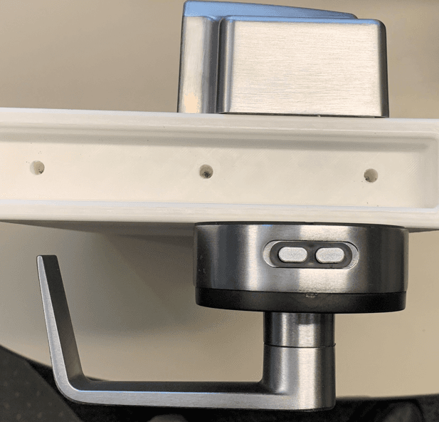
2AEI3-HB01-HL01
Jan 23, 2023A Battery Powered RFID Smart Lock
Equipment Class
DXX - Part 15 Low Power Communication Device Transmitter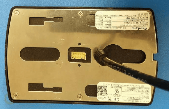
2AEI3WLTC-ER2X-SK17
Jun 11, 2020Single Gang and Key RFID Reader
Equipment Class
DCD - Part 15 Low Power Transmitter Below 1705 kHz
2AEI3WLTC-DHMM-11U2
Oct 22, 2015USB 13.56 MHz RF Front end reader/writer.
Equipment Class
DXT - Part 15 Low Power Transceiver, Rx Verified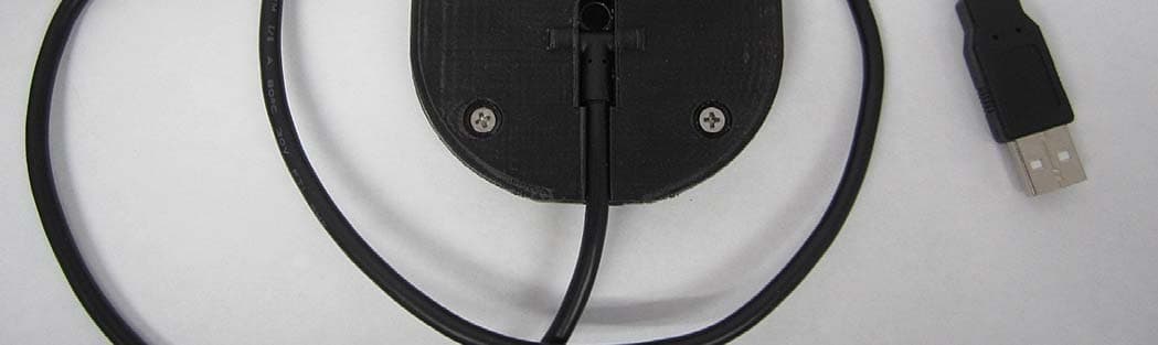
2AEI3WLTC-DHMM-11U3
Oct 22, 2015USB 125 kHz and 13.56 MHz RF Front end reader/writer.
Equipment Class
DCD - Part 15 Low Power Transmitter Below 1705 kHz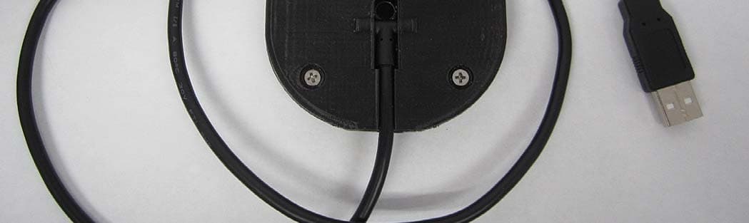
2AEI3WLTC-DHMM-11U1
Oct 22, 2015USB 125 KHz RF Front end reader/writer.
Equipment Class
DCD - Part 15 Low Power Transmitter Below 1705 kHz