Text extracted from the exhibit documents filed with the FCC. Open a document above to read the original.
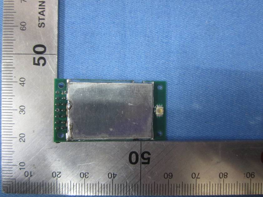
FLDSTX1 2.4GHz Module User Manual. Firelands Group, LLC 2919 Crossing Court #2 Champaign, IL 61822 1-217-493-7740 1. Features 2.4GHz radio transceiver module. Operates in the unlicensed worldwide ISM band (2409.2 to 2474.0 MHz). Fully integrated power regulation with a wide input unregulated operating range 2.0 to 3.6V. Fully integrated local oscillator and 26MHz 10ppm reference crystal Transmit power less than 100mW Receive sensitivity up to -104dBm Full packet assembling and disassembling Fully buffered digital interface with high voltage tolerant inputs 2. Pin description Pin Number Name Description 1 GND Module Ground 2 VIN Module DC Power 3 RESET_N Baseband CPU reset input 4 VIN Module DC Power 5 P1.2 Baseband CPU digital port P1.2 6 P1.4 Baseband CPU digital port P1.4 7 P1.0 Baseband CPU digital port P1.0 8 P1.1 Baseband CPU digital port P1.1 9 P0.2 Baseband CPU digital port P0.2 10 P0.3 Baseband CPU digital port P0.3 11 P0.4 Baseband CPU digital port P0.4 12 P0.5 Baseband CPU digital port P0.5 13 P2.1 Baseband CPU digital port P2.1 14 P2.2 Baseband CPU digital port P2.2 3. Specifications Parameter Value Units Storage Temp -50 to 150 Degrees Celsius VDD 2.0 to 3.6 Volts Receive Sensitivity -104 dBm Transmit power (conducted) 7 dBm MAX Transmit power (radiated) 9 dBm MAX Idle current 5 mA Receive current 20 mA Transmit current 65 mA 4. Block Diagram 5. Module User Requirements 5.1 This module must be integrated into a device where the user cannot access the antenna connector. 5.2 Only a 2dBi antenna can be used with this module. The antenna must meet and not exceed the gain and pattern of the supplied Inpaq DAM00BM11500209 folded dipole antenna. 5.3 The device must contain the following permanent labeling on the exterior of the device as follows: Contains FCC ID: 2AEIGFLDSTX1 5.4 The user manual of the device must contain the following paragraph: 6.5+/-1 FCC Information This device complies with part 15 of the FCC rules. Operation is subject to the following two conditions: (1) This device may not cause harmful interference, and (2) this device must accept any interference received, including interference that may cause undesired operation. CE Information This product contains a radio transmitter with wireless technology which has been tested and found to be compliant with the applicable regulations governing a radio transmitter in the 2.4092 GHz to 2.4740 GHz frequency range. The following countries associated regulatory agencies recognizing the noted certifications for this product as authorized for sale and use are: UK DE DK NO SE FI EE LV LT PL CZ SK HU RO SI AT IT ES PT IE NL LU MT CY GR Caution: Changes or modifications not expressly approved by the party responsible for compliance could void the user’s authority to operate the equipment. FCC Statement Thisdevicecomplieswithpart15oftheFCCRules.Operationissubjecttothefollowing twoconditions:(1)Thisdevicemaynotcauseharmfulinterference,and(2)thisdevice mustacceptanyinterferencereceived,includinginterferencethatmaycauseundesired operation. Changes or modifications not expressly approved by the party responsible for compliancecouldvoidtheuser'sauthoritytooperatetheequipment. If the FCC identification number is not visible when the module is installed inside anotherdevice,thentheoutsideofthedeviceintowhichthemoduleisinstalledmust alsodisplayalabelreferringtotheenclosedmodule.Thisexteriorlabelcanusewording suchasthefollowing:“ContainsTransmitterModuleFCCID:2AEIGFLDSTX1OrContains FCCID:2AEIGFLDSTX1ā whenthemoduleisinstalledinsideanotherdevice,theusermanualofthisdevicemust containbelowwarningstatements; 1. This device complies with Part 15 of the FCC Rules. Operation is subject to the followingtwoconditions: (1)Thisdevicemaynotcauseharmfulinterference. (2)Thisdevicemustacceptanyinterferencereceived,includinginterferencethatmay causeundesiredoperation. 2. Changes or modifications not expressly approved by the party responsible for compliancecouldvoidtheuser'sauthoritytooperatetheequipment. The devices must be installed and used in strict accordance with the manufacturer's instructionsasdescribedintheuserdocumentationthatcomeswiththeproduct
Firelands Group, LLC 2919 Crossing Court Suite 2, Champaign, IL 61822USA DATE:2015-10-29 Nemko Canada Inc 303 River Road Ottawa, Ontario, Canada K1V 1H2 Attn: Director of Certification Authority to Act as Agent On our behalf, I appointHank Yanof Global United Technology Services Co., Ltd. 2nd Floor, Block No.2, Laodong Industrial Zone, Xixiang Road Baoan District Shenzhen Guangdong(Name and address)to act as our agent in the preparation of this application for equipment certification. I certify that submitted documents properly describe the device or system for which equipment certification is sought. I also certify that each unit manufactured, imported or marketed, as defined in the Federal Communications Commission’s regulations will have affixed to it a label identical to that submitted for approval with this application. For instances where our authorized agent signs the application for certification on our behalf, I acknowledge that all responsibility for complying with the terms and conditions for certification, as specified by Nemko Canada Inc, still resides withFirelands Group, LLCand 1214 Dorchester Dr, 2919 Crossing Court Suite 2, Champaign, IL 61822USA Dated this /Day of10/29/2015/ Agency agreement expiration date:10/29/2016 By:JasonCorl SignaturePrinted Title:Manager On behalf of :Firelands Group, LLC Telephone:714 743 2155
Firelands Group, LLC 2919 Crossing Court Suite 2, Champaign,IL 61822USA DATE2015-10-29 Equipment Autorisation Division Federal Communications Commission 7435 Oakland Mills Road Columbia, MD 21046 FCC ID:2AEIGFLDSTX1 Product Name:FLDSTX1 Request for Confidentiality Pursuant to Sections 0.457 and 0.459 of the commissions rules, we hereby request that the following documents be held confidential: •Schematics •Block diagram •Operational Description These materials contain trade secrets and proprietary information and are not customarily released to the public. The public disclosure of this information might be harmful to the company and provide unjustified benefits to our competitors. Dated this /Day of10/29/2015/ By:JasonCorl SignaturePrinted Title:Manager On behalf of :Firelands Group, LLC Telephone:714 743 2155
Single Modular approval Declaration letter We ,Firelands Group, LLC apply Single modular approval for Product Name: FLDSTX1 Model: FLDSTX1 FCC ID: 2AEIGFLDSTX1 According to 996369 D01 Module Equip Auth Guide v01r04 and 15.212 requirement: 1) The radio elements must have the radio frequency circuitry shielded. Physical components and tuning capacitor(s) may be located external to the shield, but must be on the module assembly; Answer : YES, both side shielded 2) The module must have buffered modulation/data inputs to ensure that the device will comply with Part 15 requirements with any type of input signal; Answer :Ye s ;All data inputs to the module are digital and buffered through a microprocessor that then converts the digital information into analog RF signal.. 3)The modular transmitter must have its own power supply regulation. Answer :Ye s ;The module has on-board regulation and can control voltages between 2 and 3.6 volts. 4) The module must contain a permanently attached antenna, or contain a unique antenna connector, and be marketed and operated only with specific antenna(s), per Sections 15.203, 15.204(b), 15.204(c), 15.212(a), 2.929(b); Answer :Ye s ; Device is equipped with integral antenna. (5) The module must demonstrate compliance in a stand-alone configuration; Answer : Ye s ,distance between modular and all AEs are longer than 10cm ,refer to setup photo. (6) The module must be labelled with its permanently affixed FCC ID label, or use an electronic display (See KDB Publication 784748 about labelling requirements); Answer :Ye s ; The modular has a permanent fixed label, and below statement was listed in the user manual;The host device must be labeled to display the FCC ID of the module “Contains Transmitter Module FCC ID: 2AEIGFLDSTX1” or “Contains FCC ID: 2AEIGFLDSTX1.” (7) The module must comply with all specific rules applicable to the transmitter including all the conditions provided in the integration instructions by the grantee; Answer :Ye s ; The module comply with all specific rules applicable to the transmitter including all the conditions provided in the integration instructions by the grantee, Refer to test report and user manual . (8) The module must comply with RF exposure requirements Answer :Ye s ; Transmitter meets MPE calculation of 47 CFR 1.1307 . Refer to MPE Reports and Refer to modular installation manual
FLDSTX1 Label Drawing 11mm 18mm Firelands Group FLDSTX1 FCC ID: 2AEIGFLDSTX1 Note: Label applied with permanent adhesive
FCC ID:2AEIGFLDSTX1 The device has a standalone transmission. According to KDB 447498 section 4.3.1, the 1-g SAR test exclusion thresholds at test separation distances≤ 50 mm are determined by: [(max. power of channel, including tune-up tolerance, mW)/(min. test separation distance, mm)]·[√f(GHz)] ≤ 3.0 The maximum tune-up limit power is 7.02dBm(5.035mW) @ 2.4092GHz For the head and body SAR, use 5mm as the conservative minimum test separation distance, [(max. power of channel, including tune-up tolerance, mW)/(min. test separation distance, mm)]·[√f(GHz)] =1.563≤ 3.0 So standalone SAR measurements are not required for both head and body.
Global United Technology Services Co., Ltd. Report No.: GTSE15080157301 FCC Report Applicant: Firelands Group, LLC Address of Applicant: 1214 Dorchester Dr, 2919 Crossing Court Suite 2, Champaign, IL 61822 USA Equipment Under Test (EUT) Product Name:FLDSTX1 Model No.:FLDSTX1 FCC ID: 2AEIGFLDSTX1 Applicable standards: FCC CFR Title 47 Part 15 Subpart C Section 15.247:2014 Date of sample receipt: October 26, 2015 Date of Test: October 27-28, 2015 Date of report issued: October 29, 2015 Test Result : PASS * * In the configuration tested, the EUT complied with the standards specified above. Authorized Signature: Robinson Lo Laboratory Manager This report details the results of the testing carried out on one sample. The results contained in this test report do not relate to other samples of the same product and does not permit the use of the GTS product certification mark. The manufacturer should ensure that all products in series production are in conformity with the product sample detailed in this report. This report may only be reproduced and distributed in full. If the product in this report is used in any configuration other than that detailed in the report, the manufacturer must ensure the new system complies with all relevant standards. Any mention of GTS or testing done by GTS in connection with, distribution or use of the product described in this report must be approved by GTS in writing. This document cannot be reproduced except in full, without prior written approval of the Company. Any unauthorized alteration, forgery or falsification of the content or appearance of this document is unlawful and offenders may be prosecuted to the fullest extent of the law. Unless otherwise stated the results shown in this test report refer only to the sample(s) tested and such sample(s) are retained for 90 days only. Report No.: GTSE15080157301 2Version Version No.DateDescription 00October 29, 2015Original Prepared By: Date: October 29, 2015 Project Engineer Check By:Date: October 29, 2015 Reviewer Global United Technology Services Co., Ltd.Project No.: GTSE150801573RF Room 301-309, 3th Floor, Block A, Huafeng Jinyuan Business Building, No. 300 Laodong Industrial Zone,Xixiang Road, Baoan District, Shenzhen 518102 Telephone: +86 (0) 755 2779 8480 Fax: +86 (0) 755 2779 8960Page 2 of 40 Report No.: GTSE15080157301 3Contents Page 1COVER PAGE ................................................................................................................................................1 2 VERSION ........................................................................................................................................................2 3 CONTENTS ....................................................................................................................................................3 4 TEST SUMMARY ...........................................................................................................................................4 4.1 MEASUREMENT UNCERTAINTY..................................................................................................................4 5 GENERAL INFORMATION ............................................................................................................................5 5.1 CLIENT INFORMATION...............................................................................................................................5 5.2 GENERAL DESCRIPTION OF EUT ...............................................................................................................5 5.3 TEST MODE..............................................................................................................................................7 5.4 TEST FACILITY..........................................................................................................................................7 5.5 TEST LOCATION.......................................................................................................................................7 5.6 OTHER INFORMATION REQUESTED BY THE CUSTOMER...............................................................................7 5.7 DESCRIPTION OF SUPPORT UNITS.............................................................................................................7 5.8 TEST INSTRUMENTS LIST...........................................................................................................................8 6 TEST RESULTS AND MEASUREMENT DATA............................................................................................9 6.1 ANTENNA REQUIREMENT...........................................................................................................................9 6.2 CONDUCTED EMISSIONS.........................................................................................................................10 6.3 CONDUCTED PEAK OUTPUT POWER........................................................................................................13 6.4 20DBEMISSION BANDWIDTH..................................................................................................................15 6.5 CARRIER FREQUENCIES SEPARATION......................................................................................................17 6.6 HOPPING CHANNEL NUMBER..................................................................................................................19 6.7 DWELL TIME...........................................................................................................................................20 6.8 BAND EDGE...........................................................................................................................................24 6.8.1 Conducted Emission Method ...........................................................................................................24 6.8.2 Radiated Emission Method ........................................................…
Text truncated - open the document above for the full version.
Radiated Emission Conducted Emission
| # | Rule Parts | Frequency Range | Power Output |
|---|---|---|---|
| 1 | 15C | 2.41 GHz - 2.47 GHz | 5.04 mW |

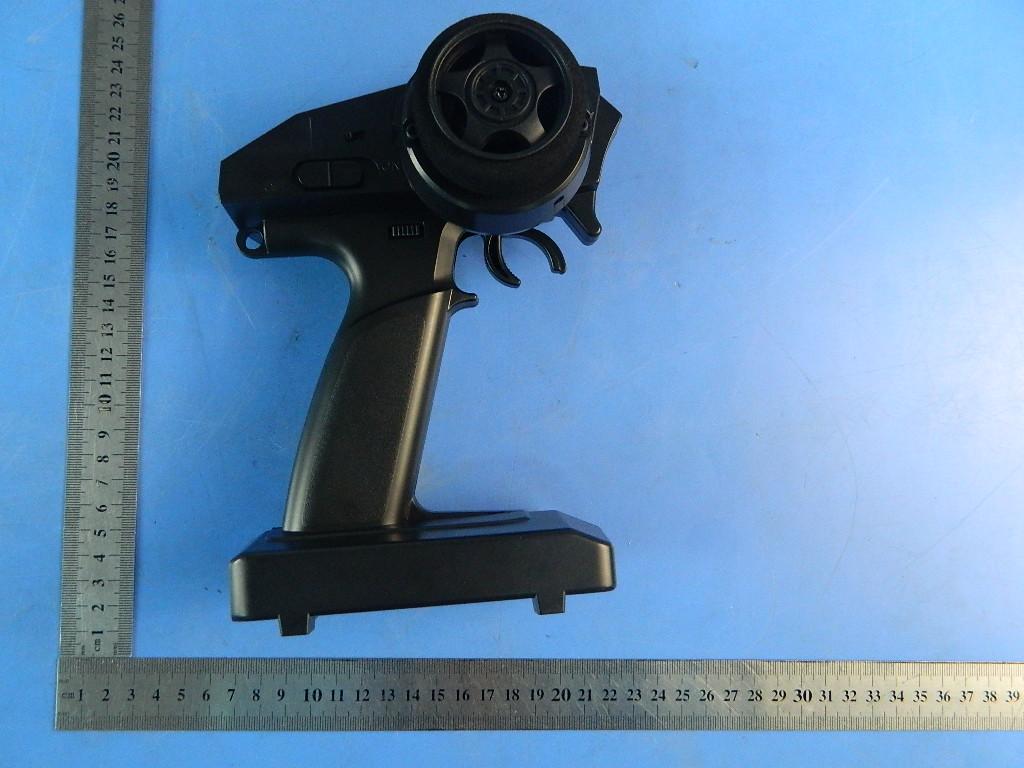
2.4GHz remote transmitter
Equipment Class
DSS - Part 15 Spread Spectrum Transmitter