2AEIM-1470138Wall Connector 3
Tesla, Inc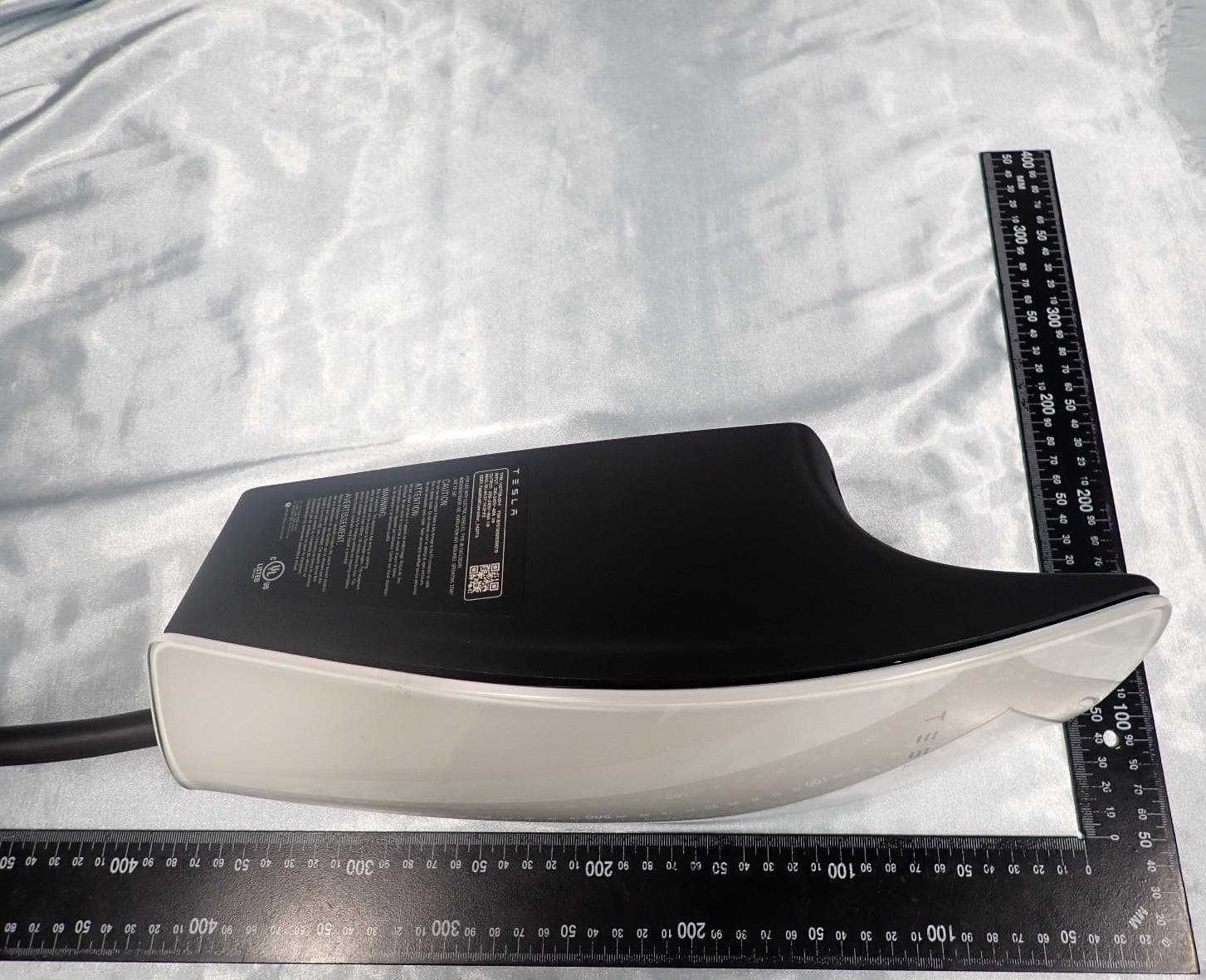
Click to zoom
Application Details
- Equipment Class
- DXX - Part 15 Low Power Communication Device Transmitter
- Date of Grant
- Sep 27, 2023
- Application Purpose
- Original Equipment
- Date of Application
- Sep 27, 2023
- Equipment Note
- Wall Connector 3
- Frequency Range
- 13.56000000 - 13.56000000
- Company
- Tesla, Inc
- Country
- United States
Documents & Files
Document Text
Text extracted from the exhibit documents filed with the FCC. Open a document above to read the original.
Users Manual
Gen 3 Wall Connector Manual 48A Single Phase Important Safety Information...........................2 Product Overview..................................................5 Product Specifications.........................................................5 Circuit Breaker Rating / Maximum Output...................7 Using Wall Connector...........................................................9 Features.....................................................................................11 Connectivity...........................................................................11 Hosted Access Point...........................................................11 Local Network.......................................................................11 Ground Fault Circuit Interruption..................................13 Ground Assurance...............................................................13 Thermal Monitoring............................................................14 Power Outages....................................................................14 Firmware Updates..............................................................14 Wall Connector External Components.........................15 Wall Connector Internal Components..........................16 Installation...............................................................17 In the Box.................................................................................17 Tools...........................................................................................18 Installation Considerations................................................19 Step 1: Prepare Wirebox for Conduit Fittings and Bushings..................................................................................22 Step 2: Prepare Mounting Surface.................................23 Step 3: Prepare Wirebox and Mount to Wall............24 Step 4: Route Wiring Through Wirebox......................25 Step 5: Strip and Land Wiring........................................26 Step 6: Attach Wall Connector to Wirebox...............27 Step 7: Energize Wall Connector...................................28 Commissioning Procedure...............................29 Setting Up Access Control...............................................30 Power Sharing.......................................................32 Power Sharing Overview...................................................32 Breaker and Branch Circuit Setup.................................33 Considerations for Power Sharing................................34 Calculating Power Sharing Requirements for Existing Systems..................................................................34 Power Sharing Commissioning Procedure.................35 Wall Connector LEDs.........................................37 Light Codes............................................................................37 Fault Codes............................................................................39 Additional Assistance for Red LED Faults...............40 Warranty Information.........................................41 Limits of Liability.................................................................42 Dispute Resolution..............................................................43 IMPORTANT SAFETY INFORMATION Read all instructions before using this product. Save these instructions. Wall Connector features built-in Type B RCD . This manual contains important instructions for the Tesla Gen 3 Wall Connector that shall be followed during installation, operation, and maintenance. Please review all warnings and cautions before installing and using the Wall Connector. WARNING: When using electric products, basic precautions should always be followed, including the following. INSTRUCTIONS RELATING TO RISK OF FIRE OR ELECTRIC SHOCK WARNING: Do not install or use the Wall Connector near flammable, explosive, harsh, or combustible materials, chemicals, or vapors. WARNING: Turn off power at the circuit breaker before installing or cleaning the Wall Connector. WARNINGS WARNING: This product can expose you to one or more chemicals that are known to the state of California to cause cancer. WARNING: This device should be supervised when used around children. WARNING: The Wall Connector must be grounded through a permanent wiring system or an equipment-grounded conductor. WARNING: Use the Wall Connector only within the specified operating parameters. WARNING: Never spray water or any other liquid directly at the wall mounted control box. Never spray any liquid onto the charge handle or submerge the charge handle in liquid. Store the charge handle in the dock to prevent unnecessary exposure to contamination or moisture. WARNING: Do not use the Wall Connector if it is defective, appears cracked, frayed, broken, or otherwise damaged, or fails to operate. WARNING: Do not use the Wall Connector if the flexible power cord or cable is frayed, broken, or otherwise damaged, or fails to operate. WARNING: Do not attempt to disassemble, repair, tamper with, or modify the Wall Connector. The Wall Connector is not user serviceable. Contact Tesla for any repairs or modification. WARNING: When transporting the Wall Connector, handle with care. Do not subject it to strong force or impact or pull, twist, tangle, drag, or step on the Wall Connector, to prevent damage to it or any components. 2Gen 3 Wall Connector Manual WARNING: Do not touch the Wall Connector’s end terminals with fingers or sharp metallic objects, such as wire, tools, or needles. WARNING: Do not insert fingers or foreign objects into any part of the Wall Connector. WARNING: Do not forcefully fold or apply pressure to any part of the Wall Connector or damage it with sharp objects. WARNING: Use of the Wall Connector may affect or impair the operation of any medical or implantable electronic devices, such as an implantable cardiac pacemaker or an implantable cardioverter defibrillator. Check with your electronic device m…
Text truncated - open the document above for the full version.
Users Manual
Step 1: Prepare Wirebox for Conduit Fittings and Bushings The default conduit size is 3/4 in (21 mm). 1 in (27 mm) conduit is acceptable if needed. Based on fittings and conduit size, prepare the wirebox. • For top or bottom entry: Manually remove the conduit plug. • For rear entry: Drill with 1-1/8 in (29 mm) step bit to prepare wirebox for fittings. Table 1. For 3/4 in (21 mm) Conduit Top EntryBottom EntryRear Left EntryRear Right Entry 1-1/8 in (29 mm) 1-1/8 in (29 mm) Table 2. For 1 in (27 mm) Conduit Top EntryBottom EntryRear Left EntryRear Right Entry Do not expand. 1-3/8 in (35 mm) 1-3/8 in (35 mm)1-3/8 in (35 mm) NOTE: For 1 in (27 mm) rear and bottom entry options, drill with 1-3/8 in (35 mm) step bit to prepare wirebox for fittings. INSTALLATION 22Gen 3 Wall Connector Manual Step 2: Prepare Mounting Surface 1. If applicable, use a stud finder to locate a wooden support stud. Plywood, or other flat wall surfaces capable of supporting the weight of the Wall Connector, may also be used. 2. Based on the chosen wire entry path, position the included cardboard mounting template onto the installation surface and use a 5/32 in (4 mm) bit to drill two pilot holes (one from the top row and one from the bottom row). NOTE: When installing for rear left or rear right wire entry, select the two mounting holes that are on the opposite side of the wire entry point. NOTE: Use a level tool with the cardboard mounting template to ensure a level installation as desired. Drill bit, 5/32 in (4 mm) Top EntryBottom EntryRear Left EntryRear Right Entry INSTALLATION 23Gen 3 Wall Connector Manual Step 3: Prepare Wirebox and Mount to Wall 1. Use a 1/4 in (6.5 mm) bit to drill two pilot holes into the wirebox that match the locations chosen on the cardboard mounting template. Drill bit, 1/4 in (6.5 mm) Top EntryBottom EntryBottom Left EntryBottom Right Entry 2. Attach the wirebox to the mounting location using the included 4 mm hex bit and the two included wood fastener screws. NOTE: Type 3R rating is only possible when washers have sealing gaskets. If mounting to alternate surface (such as a prefabricated pedestal), use alternate fasteners with sealing washers. NOTE: The wood fastener screws are designed to support the weight of the entire Wall Connector, cable, and charging handle. INSTALLATION 24Gen 3 Wall Connector Manual Step 4: Route Wiring Through Wirebox 1. Route wiring into selected entry point and through the service loop channel on the right side of the wirebox. Top EntryBottom EntryRear Left EntryRear Right Entry 2. Use appropriate cable glands, bushings, or fittings to secure the wiring in place and protect from water and debris intrusion. CAUTION: Ensure that bushings are in place to avoid damage to conductors and ground wire when pulled into wirebox. CAUTION: Use copper conductors only. NOTE: Compression-style fittings are recommended to prevent interference. NOTE: For top or bottom wire entry, if installing fittings with a set screw, ensure that the screw is positioned to avoid interference with Wall Connector cables. INSTALLATION 25Gen 3 Wall Connector Manual Step 5: Strip and Land Wiring 1. Strip insulation from wires ~1/2 in (~13 mm), route through service channel, and land each wire in its correct terminal block. NOTE: Terminals are bi-directional. 2. Secure the wiring in the service channel using the included zip tie. 3. Use a torque driver and the included 4 mm hex bit to torque the terminal screws to 50 lbf . in (5.6 Nm). NOTE: When installing Wall Connector in a split phase electrical system, use Line-to-Line instead of Line-to-Neutral. INSTALLATION 26Gen 3 Wall Connector Manual Step 6: Attach Wall Connector to Wirebox 1. Attach the main unit to the wirebox by pushing it inward. 2. Secure the main unit to the wirebox with the four included fasteners and the included 4 mm hex bit using a bit driver, applying pressure to the faceplate during the process to compress the internal seal. Firmly hand-tighten the four fasteners until they are secure. NOTE: Do not use a power drill for this step. INSTALLATION 27Gen 3 Wall Connector Manual Step 7: Energize Wall Connector 1. Energize the Wall Connector by turning on the upstream circuit breaker. The Wall Connector's LEDs will turn on. See Wall Connector LEDs on page 37. 2. Proceed with commissioning. INSTALLATION 28Gen 3 Wall Connector Manual COMMISSIONING PROCEDURE The commissioning process for Wall Connector enables easy configuration of circuit breaker size, Wi-Fi connectivity, and power sharing options. 1. Turn on Wall Connector's corresponding branch breaker to energize the unit. During startup, Wall Connector will display green LEDs for 10 seconds to indicate the maximum circuit breaker it is configured for. 2. Use a Wi-Fi-enabled device such as a smart phone to connect to the SSID Wi-Fi signal broadcasted by the Wall Connector. Joining the Wall Connector network can be done by scanning the sticker QR code on the Quickstart Guide cover page, or by manually selecting the network and typing in the WPA2 password (found on the sticker on the Quickstart Guide cover page). NOTE: The Wi-Fi network will broadcast for 15 minutes.To have the Wall Connector broadcast the SSID again, hold the button on the charging handle for 5 seconds or turn the circuit breaker off, then on again. NOTE: If you are unable to connect to the Wall Connector SSID, turn off the cellular data function on your mobile device and try again. 3. Scan the QR code below with the device that is connected to the Wall Connector to access the web browser commissioning interface. Alternatively, manually type the URL address (http://192.168.92.1) into the web browser. 4. Follow the onscreen commissioning steps on the web browser to assign Wall Connector to its own circuit breaker and connect it to the local site Wi-Fi network. 29Gen 3 Wall Connector Manual NOTE: To have the Wall Connector broadcast the SSID again, hold the button on the charge handle for 5 seconds or turn the circuit…
Text truncated - open the document above for the full version.
Users Manual
WALL CONNECTOR LEDS Light Codes Startup Once energized at the circuit breaker, every LED (seven total) on the faceplate will illuminate for up to five seconds. After Startup After Wall Connector is energized at the circuit breaker, certain green LEDs (depending on the circuit breaker size) will illuminate for 10 seconds. See table below for exact light codes. Circuit breaker60 A50 A40 A30 A20 A15 A Maximum output48 A40 A32 A24 A16 A12 A NOTE: To re-display the green LEDs after the initial 10 seconds, press and hold the charging handle button. When multiple Wall Connectors are linked for power sharing, the center blue LED will illuminate during the 10-second startup window. Other Standby, waiting to plug inCharging in progress SSID broadcasting, ready to commission Waiting to charge, communicating with vehicle Top green solidEvery green streamingGreen pulsingBlue solid 37Gen 3 Wall Connector Manual Standby, waiting to plug inCharging in progress SSID broadcasting, ready to commission Waiting to charge, communicating with vehicle WALL CONNECTOR LEDS 38Gen 3 Wall Connector Manual Fault Codes All red blink codes pause for one second, and then repeat. Light BarWhat It MeansDetails No LightsPower supply issue, charging disabled Verify that the power supply is turned on. If the issue persists, have an electrician remove the Wall Connector from the wirebox and confirm that voltage is present at the terminal block using a multimeter. Record the voltage readings for the following: L1 to L2/N, L1 to Ground, L2/N to Ground. Solid redInternal , charging disabled Turn the circuit breaker off, wait 5 seconds, and turn it back on. If solid red light remains, document part number and serial number, then contact Tesla Energy. One (1) red blink Ground fault circuit interruption due to unsafe current path, charging disabled Inspect the handle, cable, Wall Connector, and vehicle charge port for damage or signs of water ingress. Have an electrician check that ground is not directly connected to a conductor wire in the branch circuit. Two (2) red blinks Ground assurance fault, high ground resistance detected, charging disabled Verify that the Wall Connector is properly grounded. The ground connection must be bonded in the upstream power supply for proper operation. Check all physical connections, including the wirebox terminals, electrical panel(s), and junction boxes. In residential power supplies, check the bond between ground and neutral at the main panel. If connected to a transformer, contact the transformer's manufacturer for direction on how to bond the ground connection. Three (3) red blinks High temperature detected; charging limited or disabled Verify that Wall Connector is connected to Wi-Fi and updated with the latest available firmware for optimal temperature sensing functionality. Check the faceplate and cable handle for excessive warmth. Have an electrician remove the Wall Connector from the wirebox and verify that the conductors used are sized correctly and that the terminal block is torqued to specification. Connect Wall Connector to Wi-Fi so that firmware can update to most recent version. If firmware does not automatically update, use the Commissioning Procedure on page 29 to sign into the commissioning wizard and manually update the firmware. If it does not solve the problem, contact our Customer Support team. Four (4) red blinks Internet connection lost, online features disabled Check for objects that could interfere with the area's Wi-Fi signal strength. Confirm that the local Wi-Fi router is operational. If the Wi-Fi password was changed recently, follow the commissioning process on your mobile device to update the Wi-Fi settings. Five (5) red blinks Power-sharing communication issue, charging reduced Check for objects that could interfere with the area's Wi-Fi signal strength. Follow the commissioning process on your mobile device to re-link the Wall Connectors for power-sharing. Six (6) red blinks Overvoltage or poor grid quality detected, charging disabled Verify that the power supply is nominal 200-240 volts. If the issue persists, have an electrician remove the Wall Connector from the wirebox and confirm that voltage readings are as expected at the terminal block using a multimeter. Record the voltage readings for the following: L1 to L2/N, L1 to Ground, L2/N to Ground. WALL CONNECTOR LEDS 39Gen 3 Wall Connector Manual All red blink codes pause for one second, and then repeat. Light BarWhat It MeansDetails Seven (7) red blinks Vehicle overcurrent detected Reduce the vehicle's charge current setting. If the issue persists and the attached vehicle is manufactured by Tesla, record the vehicle's VIN and approximate time of the fault and contact Tesla. If the vehicle is not manufactured by Tesla, contact the vehicle's manufacturer. Additional Assistance for Red LED Faults A Wall Connector's alerts are visible in the browser commissioning wizard (for instructions on how to connect to the commissioning wizard, see Commissioning Procedure on page 29). If additional assistance is required, have the following information prepared before contacting Tesla: • Short video of Wall Connector LED activity during faulted state • Photo of Wall Connector's part number and serial number (located on the side label) • Timeframe that the issue was observed • VIN of vehicle that plugged into Wall Connector at time of faulted state • Photo of any error messages displayed on the vehicle's screen Visit tesla.com/support/contact or scan the QR code below to request support. Optionally, for owner support and issue troubleshooting: (888) 765-2489 For North America Electrician and Installer support: (650) 963-5655 WALL CONNECTOR LEDS 40Gen 3 Wall Connector Manual WARRANTY INFORMATION Subject to the exclusions and limitations described below, the Charging Equipment Limited Warranty covers the refund, repair or replacement necessary to remedy any manufacturing defects in a Tesla manufactured and supplied Wall Connec…
Text truncated - open the document above for the full version.
Attestation Statements
Tesla, Inc. 3500 Deer Creek Road Palo Alto, California, U.S.A. Federal Communications Commission 7435 Oakland Mills Road Columbia MD 21046 Date: September 13, 2023 Subject: Certifications concerning “covered” equipment pursuant to Part 2.911(d)(5)(i) and (ii) To whom it may concern, TESLA certifies that the equipment [FCC ID: 2AEIM-1470138] for which authorization is sought is not “covered” equipment prohibited from receiving an equipment authorization pursuant to section 2.903 of the FCC rules. TESLA certifies that, as of the date of the filing of the application, the applicant [is not] identified on the Covered List (as a specifically named entity or any of its subsidiaries or affiliates) as an entity producing “covered” equipment. Sincerely, ________________________ Viraj Andrabadu Kurundu Patabendige [email protected]
Attestation Statements
Tesla, Inc. 3500 Deer Creek Road Palo Alto, California, U.S.A. Federal Communications Commission 7435 Oakland Mills Road Columbia MD 21046 Date: September 13, 2023 Subject: Certifications concerning “covered” equipment pursuant to Part 2.911(d)(5)(i) and (ii) To whom it may concern, TESLA certifies that the equipment [FCC ID: 2AEIM-1470138] for which authorization is sought is not “covered” equipment prohibited from receiving an equipment authorization pursuant to section 2.903 of the FCC rules. TESLA certifies that, as of the date of the filing of the application, the applicant [is not] identified on the Covered List (as a specifically named entity or any of its subsidiaries or affiliates) as an entity producing “covered” equipment. Sincerely, ________________________ Viraj Andrabadu Kurundu Patabendige [email protected]
Attestation Statements
Tesla, Inc. 3500 Deer Creek Road Palo Alto, California U.S.A. Federal Communications Commission 7435 Oakland Mills Road Columbia MD 21046 Subject: Certification designating a U.S. agent for service of process pursuant to Part 2.911(d)(7) To whom it may concern, [Tesla, Inc., Grantee Code 2AEIM] (“the applicant”) as required by section 2.911(d)(7), will also serve as the agent for service of process for the above referenced FCC Grantee Code. The service of process includes, but is not limited to, delivery of any correspondence, notices, orders, decisions, and requirements of administrative, legal, or judicial process related to Commission proceedings. The applicant acknowledges that they will maintain an agent for service of process in the United States for no less than one year after either the grantee has permanently terminated all marketing and importation of the applicable equipment within the U.S., or the conclusion of any Commission-related administrative or judicial proceeding involving the equipment, whichever is later. The applicant further acknowledges their responsibility to inform the FCC whenever the following agent information changes. Company Name: Tesla, Inc. Company US Address: 3500 Deer Creek Road, Palo Alto, CA, United States 94304 Contact Person: Viraj Andrabadu Kurundu Patabendige Email: [email protected] FRN: 0024474967 Sincerely yours, Signed by the Applicant Name: Viraj Andrabadu Kurundu Patabendige Title: Sr Manager, Compliance Engineering Email: [email protected] Date: April 13, 2023
Cover Letter(s)
Authorization on Behalf of Tesla Inc. For the US Federal Communications Commission Office of Engineering and Technology and other FCC Programs and Offices 1. I, Sean Lui, am on the Compliance Team of Tesla Inc and Applicant/Grantee Contact of Record for Tesla Inc. together with its subsidiaries and affiliates worldwide (collectively, “Tesla, Inc”) for Tesla’s dealings with the United States Federal Communications Commission (“FCC”). I am duly authorized by Tesla Inc. to make this Authorization on Tesla Inc.’s behalf. 2. This authorization will designate the person named below to act on my behalf and Tesla Inc.’s behalf as authorized agent and representative, until further notice, with the additional power to designate one or more third party agents for Tesla Inc. with regard to particular matters and applications. All acts carried out and requests made by this named representative relating to any matter before the FCC, including requests for confidentiality, shall have the same effect as mine. Name: Viraj Andrabadu Kurundu Patabendige Title: Sr Manager, Compliance Engineering Address: 3500 Deer Creek Road Palo Alto, California 94304 Telephone: 650-339-5597 Email: [email protected] 3. Questions about the scope and effect of this Authorization should be addressed as follows: Sean Lui 3500 Deer Creek Road Palo Alto, California 94304 650-681-5109 [email protected] 4. I declare under penalty of perjury that the foregoing is true and correct, and that this Authorization was executed in California on the date indicated below my signature. ________________________________ Signature Sean Lui Tesla Inc. Date: 20 December 2022
Cover Letter(s)
Tesla, Inc. 3500 Deer Creek Road Palo Alto, California, U.S.A. Date: September 12, 2023 FCC Laboratory 7435 Oakland Mills Rd Columbia MD 21046 Subject: Request for Confidentiality FCC ID: 2AEIM-1470138 To Whom It May Concern, Pursuant to the provisions of Sections 0.457 and 0.459 of Commission’s rules (47CFR§§0.457, 0.459), we are requesting the Commission to withhold the following documents from public disclosure indefinitely. Schematic Diagram Block Diagram Part List Operational Description Above mentioned documents which contain detailed system and equipment description are considered as proprietary information in operation of the equipment. The public disclosure of above documents might be harmful to our company and would give competitor an unfair advantage in the market. In additional to above mentioned documents, pursuant to Public Notice DA 04-1705 of the Commission’ s policy, in order to comply with the marketing regulations in 47 CFR §2.803 and the importation rules in 47 CFR §2.1204, while ensuring that business sensitive information remains confidential until the actual marketing of newly authorized devices, we are requesting the Commission to withhold the following documents for 180 days after the grant of equipment authorization is issued: External Photos Internal Photos Test Setup Photos User Manual It is our understanding that all measurement test reports, FCC ID label format cannot be granted as confidential documents and those information will be available for public review once the grant of equipment authorization is issued. Best Regards, _______________________ Viraj Andrabadu Kurundu Patabendige [email protected]
Cover Letter(s)
Tesla, Inc. 3500 Deer Creek Road Palo Alto, California, U.S.A. FCC Agent Authorization Date: September 11, 2023 To whom it may concern, Tesla, Inc. hereby authorize Sporton International Inc. to act on our behalf in all matters relating to applications for FCC equipment authorization, including the signing of all documents relating to these matters. Any and all acts carried out by Sporton International Inc. on our behalf shall have the same effect as acts of our own. We also hereby certify that neither the applicant nor any party to the application is subject to a denial of Federal benefits that includes FCC benefits pursuant to section 5301 of the Anti-Drug Abuse Act of 1988. 21 U.S.C. 862. This authorization is limited to the product of as following: FCC ID: 2AEIM-1470138 This authorization is valid until further written notice from Tesla, Inc. Sincerely, ________________________ Viraj Andrabadu Kurundu Patabendige [email protected]
External Photos
PHOTOGRAPHS OF EUT Report No.: EP230726002 TEL : 408 9043300 Page Number : 1 of 15 Issue Date : Aug. 24, 2023 Report Version : 02 1. External Photograph of EUT Brand Name: Tesla / Model Name: 1470138-XX-Y / HVIN: 1470138 PHOTOGRAPHS OF EUT Report No.: EP230726002 TEL : 408 9043300 Page Number : 2 of 15 Issue Date : Aug. 24, 2023 Report Version : 02 PHOTOGRAPHS OF EUT Report No.: EP230726002 TEL : 408 9043300 Page Number : 3 of 15 Issue Date : Aug. 24, 2023 Report Version : 02 PHOTOGRAPHS OF EUT Report No.: EP230726002 TEL : 408 9043300 Page Number : 4 of 15 Issue Date : Aug. 24, 2023 Report Version : 02 PHOTOGRAPHS OF EUT Report No.: EP230726002 TEL : 408 9043300 Page Number : 5 of 15 Issue Date : Aug. 24, 2023 Report Version : 02 PHOTOGRAPHS OF EUT Report No.: EP230726002 TEL : 408 9043300 Page Number : 6 of 15 Issue Date : Aug. 24, 2023 Report Version : 02
ID Label/Location Info
Label Location on the side of EUT EUT Label
Internal Photos
PHOTOGRAPHS OF EUT Report No.: EP230726002 TEL : 408 9043300 Page Number : 7 of 15 Issue Date : Aug. 24, 2023 Report Version : 02 2. Internal Photograph of EUT Brand Name: Tesla / Model Name: 1470138-XX-Y / HVIN: 1470138 PHOTOGRAPHS OF EUT Report No.: EP230726002 TEL : 408 9043300 Page Number : 8 of 15 Issue Date : Aug. 24, 2023 Report Version : 02 PHOTOGRAPHS OF EUT Report No.: EP230726002 TEL : 408 9043300 Page Number : 9 of 15 Issue Date : Aug. 24, 2023 Report Version : 02 PHOTOGRAPHS OF EUT Report No.: EP230726002 TEL : 408 9043300 Page Number : 10 of 15 Issue Date : Aug. 24, 2023 Report Version : 02 PHOTOGRAPHS OF EUT Report No.: EP230726002 TEL : 408 9043300 Page Number : 11 of 15 Issue Date : Aug. 24, 2023 Report Version : 02 PHOTOGRAPHS OF EUT Report No.: EP230726002 TEL : 408 9043300 Page Number : 12 of 15 Issue Date : Aug. 24, 2023 Report Version : 02 PHOTOGRAPHS OF EUT Report No.: EP230726002 TEL : 408 9043300 Page Number : 13 of 15 Issue Date : Aug. 24, 2023 Report Version : 02 PHOTOGRAPHS OF EUT Report No.: EP230726002 TEL : 408 9043300 Page Number : 14 of 15 Issue Date : Aug. 24, 2023 Report Version : 02 NFC Antenna PHOTOGRAPHS OF EUT Report No.: EP230726002 TEL : 408 9043300 Page Number : 15 of 15 Issue Date : Aug. 24, 2023 Report Version : 02 ─────THE END────
RF Exposure Info
TEL : 886-3-327-3456 Page : 1 of 5 FAX : 886-3-328-4978 Issued Date : Aug. 24, 2023 Form version: 200414 RF EXPOSURE EVALUATION REPORT Report No. : FA230726002 RF EXPOSURE EVALUATION REPORT FCC ID : 2AEIM-1470138 Equipment : Wall Connector 3 Brand Name : Tesla Model Name : 1470138-XX-Y Applicant : Tesla, Inc. 3500 DEER CREEK ROAD PALO ALTO, CA 94304 Manufacturer : Tesla, Inc. 3500 DEER CREEK ROAD PALO ALTO, CA 94304 Standard : 47 CFR Part 2.1091 We, SPORTON INTERNATIONAL INC has been evaluated this product in accordance with 47 CFR Part2.1091 and it complies with applicable limit. Sporton Lab is accredited to ISO 17025 by Taiwan Accreditation Foundation (TAF code: 1190) and the FCC designation No. TW1190 under the FCC 2.948(e) by Mutual Recognition Agreement (MRA) in FCC evaluation. The results in this report apply exclusively to the tested model / sample. Without written approval of SPORTON INTERNATIONAL INC. Laboratory, the test report shall not be reproduced except in full SPORTON INTERNATIONAL INC. EMC & Wireless Communications Laboratory No. 52, Huaya 1st Rd., Guishan Dist., Taoyuan City, Taiwan (R.O.C.) Approved by: Cona Huang / Deputy Manager TEL : 886-3-327-3456 Page : 2 of 5 FAX : 886-3-328-4978 Issued Date : Aug. 24, 2023 Form version: 200414 RF EXPOSURE EVALUATION REPORT Report No. : FA230726002 Table of Contents 1. DESCRIPTION OF EQUIPMENT UNDER TEST (EUT) ............................................................................. 4 2. MAXIMUM RF AVERAGE OUTPUT POWER AMONG PRODUCTION UNITS ........................................ 4 3. RF EXPOSURE LIMIT INTRODUCTION .................................................................................................... 5 4. RADIO FREQUENCY RADIATION EXPOSURE EVALUATION ............................................................... 5 4.1. Standalone Power Density Calculation ............................................................................................. 5 TEL : 886-3-327-3456 Page : 3 of 5 FAX : 886-3-328-4978 Issued Date : Aug. 24, 2023 Form version: 200414 RF EXPOSURE EVALUATION REPORT Report No. : FA230726002 History of this test report Report No. Version Description Issued Date FA230726002 Rev. 01 Initial issue of report Aug. 18, 2023 FA230726…
Text truncated - open the document above for the full version.
Contact Information
Applicant
Sean Lui(International Compliance Engineer, Charging)
Test Firm
Sporton International (USA) IncKevin Lu
[email protected]16692729004
Technical Specifications
| # | Rule Parts | Frequency Range | Power Output |
|---|---|---|---|
| 1 | 15C | 13.56 MHz - 13.56 MHz | - |
Other Applications from Tesla, Inc
2AEIM-5443322
Jun 17, 2026Megacharger Handle
Equipment Class
DTS - Digital Transmission System2AEIM-WC8
Jun 02, 2026Wireless Phone Charger
Equipment Class
DXX - Part 15 Low Power Communication Device Transmitter2AEIM-2141065
Apr 13, 2026B Pillar Endpoint
Equipment Class
DTS - Digital Transmission System2AEIM-2167704
Apr 13, 2026B Pillar Endpoint
Equipment Class
DXX - Part 15 Low Power Communication Device Transmitter2AEIM-2145520
Apr 13, 2026Tuk Tuk Endpoint
Equipment Class
UWB - Ultra Wideband Transmitter