2AEIM-154158476-77 GHz Automotive Radar
Tesla, Inc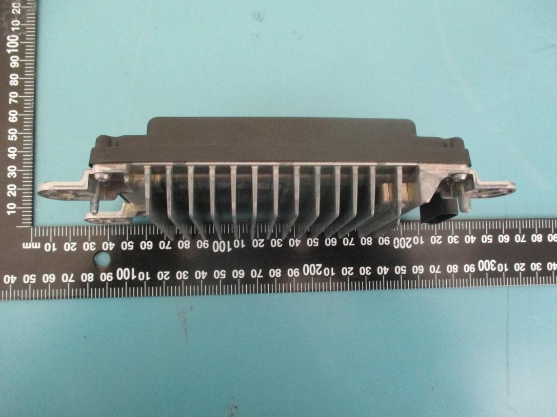
Click to zoom
Application Details
- Equipment Class
- VRD - Part 95 Vehicular Radar Systems
- Date of Grant
- Jun 06, 2022
- Application Purpose
- Original Equipment
- Date of Application
- Jun 06, 2022
- Equipment Note
- 76-77 GHz Automotive Radar
- Frequency Range
- 76000.00000000 - 77000.00000000
- Company
- Tesla, Inc
- Country
- United States
Documents & Files
Document Text
Text extracted from the exhibit documents filed with the FCC. Open a document above to read the original.
Users Manual
Consumer Information 361 How It Works Your Model X includes the following Autopilot components that actively monitor the surrounding roadway: 1. A camera is mounted above the rear license plate. 2. Ultrasonic sensors are located in the front and rear bumpers. 3. A camera is mounted in each door pillar. 4. Three cameras are mounted to the windshield above the rear view mirror. 5. A camera is mounted to each front fender. 6. Radar is mounted behind the front bumper. Model X is also equipped with high precision electronically-assisted braking and steering systems. NOTE: Ensure all cameras and sensors are clean before each drive. See Cleaning Cameras and Sensors on page 102 for more information. Unclean cameras and sensors, as well as environmental conditions such as rain and faded lane markings, can affect Autopilot performance. Features NOTE: Depending on market region, vehicle configuration, options purchased, and software version, your vehicle may not be equipped with all Autopilot features listed below, or a feature may not operate exactly as described. These Autopilot features are designed to increase your safety: • Lane Assist (see Lane Assist on page 136) • Collision Avoidance Assist (see Collision Avoidance Assist on page 139) • Speed Assist (see Speed Assist on page 143) • Auto High Beam (see High Beam Headlights on page 64) These Autopilot convenience features are designed to reduce driver workload: • Traffic-Aware Cruise Control (see Traffic- Aware Cruise Control on page 103) • Autosteer (see Autosteer on page 109) • Auto Lane Change (see Auto Lane Change on page 111) • Autopark (see Autopark on page 126) • Summon (see Summon on page 128) • Smart Summon (Smart Summon on page 132) • Navigate on Autopilot (see Navigate on Autopilot on page 114) Consumer Information 362 • Stop Light and Stop Sign Warning (see Stop Light and Stop Sign Warning on page 112) • Traffic Light and Stop Sign Control (see Traffic Light and Stop Sign Control on page 117) You can enable/disable some of these features and in some cases, control how they work. To access settings, touch Controls > Autopilot. Limitations Traffic-Aware Cruise Control is particularly unlikely to operate as intended in the following types of situations: • The road has sharp curves. • Visibility is poor (due to heavy rain, snow, fog, etc.). • Bright light (such as from oncoming headlights or direct sunlight) is interfering with the view of the camera(s). • The radar sensor is obstructed (dirty, covered, etc.). • The windshield is obstructing the view of the camera(s) (fogged over, dirty, covered by a sticker, etc.). WARNING: The list above does not represent an exhaustive list of situations that may interfere with proper operation of Traffic-Aware Cruise Control. Consumer Information 363 ALL REGIONS - FCC and IC Certification Component Manufacturer Model Operating Frequency (MHz) FCC ID IC Radar Tesla 1541584 76000-77000 2AEIM-1541584 20098-1541584 The device listed above comply with Part 15 of the FCC rules and Industry Canada's license-exempt RSS Standard(s) and EU Directive 2014/53/EU. Operation is subject to the following two conditions: 1. This device may not cause harmful interference; and 2. This device must accept any interference received, including interference that may cause undesired operation. Changes or modifications not expressly approved by Tesla could void your authority to operate the equipment. Le présent appareil est conforme aux CNR d'Industrie Canada applicables aux appareils radioexempts de licence. L'exploitation est autorisée aux deux conditions suivantes : 1. l'Appareilne doit pas produire de brouillage, et 2. l'Utilisateur de l'appareil doit accepter tout brouillage radioélectrique subi, même si le brouillage est susceptible d'en compromettre lefonctionnement. Radiation Exposure Statement The product complies with the FCC/IC RF Exposure for Low Power Consumer Wireless Power Transfer. The RF exposure limit set forth for an uncontrolled environment and are safe for intended operation as described in this manual. The furthest RF exposure that compliance was demonstrated at 20cm or greater separation from the user body. Cet équipement est conforme aux limites d’exposition aux rayonnements IC établies pour unenvironnement non contrôlé. Déclaration d'exposition aux radiations: Le produit est conforme à l'exposition RF IC pour le transfert de puissance sans fil de consommateurs de faible puissance. La limite d'exposition RF fixée pour un environnement non contrôlé est sans danger pour le fonctionnement prévu tel que décrit dans ce manuel. L'exposition RF supplémentaire que la conformité a été démontrée à 20cm et plus de séparation du corps de. ALL REGIONS - Radio Frequency Information This equipment has been tested and found to comply with the limits for a Class B digital device, pursuant to Part 15 of the FCC Rules. These limits are designed to provide reasonable protection against harmful interference in a residential installation. This equipment generates, uses and can radiate radio frequency energy and, if not installed and used in accordance with the instructions, may cause harmful interference to radio communications. However, there is no guarantee that interference will not occur in a particular installation. If this equipment does cause harmful interference to radio or television reception, which can be determined by turning the equipment off and on, try to correct the interference by one or more of the following measures: • Reorient or relocate the receiving antenna. • Increase the separation between the equipment and receiver. • Connect the equipment into an outlet on a circuit different from that to which the receiver is connected. • Consult the dealer or an experienced radio/TV technician to help. Consumer Information 364 CAUTION: This equipment and its antennas must not be co-located or operated with another antenna or transmitter. ALL REGIONS - RF Modules The devices described below have been evaluate…
Text truncated - open the document above for the full version.
Cover Letter(s)
Tesla, Inc. 3500 Deer Creek Road, Palo Alto, CA 94304 p +650 681 5100 f +650 681 5101 Federal Communications Commission Office of Engineering & Technology Authorization and Evaluation Division 7435 Oakland Mills Road Columbia, MD 21046 Via Electronic Filing Date: April 28, 2021 Re: Authorized Personnel for Grantee Code 2AEIM To Whom It May Concern: I currently serve as Tesla, Inc’s (Tesla) grantee contact (Grantee Code 2AEIM) for Federal Communications Commission (FCC) equipment authorizations. As prescribed in KDB 852134 Authorized Policy Form 731, I authorize the following personnel to act on Tesla’s behalf with regard to all matters that relate to FCC equipment authorization (i.e., signing Form 731, attestation letters, and confidentiality request letters). These individuals also are authorized to assign additional persons to act on Tesla’s behalf as authorized agents. Authorized Personnel: • Peng Zhang • Cindy Li This authorization is valid until further written notice from any of Tesla’s authorized grantee contacts. Sincerely Yours, Sean Lui Sr. Staff Charging Compliance Engineer 3500 Deer Creek Road, Palo Alto, California US 94304 Phone: (650)681-5109 [email protected]
Cover Letter(s)
FCC Confidential Authorization 2021-10-06 FEDERAL COMMUNICATIONS COMMISSIONS Authorization and Evaluation Division 7435 Oakland Mills Road Columbia, MD 21046 Subject: Confidentiality Request regarding application for certification of FCC ID: 2AEIM-1541584 In accordance with Sections 0.457 and 0.459 of the Commission’s Rules, Tesla, Inc hereby requests long-term confidential treatment of information accompanying this application as outlined below: Block Diagram Schematics Operation Description Parts List Internal Photos As well as short-term (180 days) confidential treatment of information accompanying this application as outlined below: User’s Manual External Photos Test Set-up Photos The above materials contain proprietary and confidential information not customarily released to the public. The public disclosure of these materials provides unjustified benefits to its competitors in the market. Sincerely, Cindy Li C ertification Engineer Tesla, Inc 3500 Deer Creek Road, Palo Alto, C A 94304
Cover Letter(s)
Authorization Letter Date: 2022-11-18 FEDERAL COMMUNICATIONS COMMISSIONS Authorization and Evaluation Division 7435 Oakland Mills Road Columbia, MD 21046 We, Tesla, Inc., want to submit this request for our device, model number: 1541584, which was granted on 2022-06-07 under FCC ID: 2AEIM-1541584. According to FCC confidentiality policy, the exhibits: User Manual Internal photos External photos Test Setup photos are listed under short-term confidentiality, and those documents will be available to public on 2022-12-07. However, this device will not be marketed until Mid-January 2023. To avoid any unnecessary disclosure and competitive harm before our product launching, we would like to request above exhibits to be held for another 60 days until 2023-02-07. We, Tesla, Inc. authorizes Bay Area Compliance Laboratories Corp. to act on behalf of us and take care this process. This authorization is valid until further written notice from the applicant. Sincerely, Cindy Li Certification Engineer Tesla, Inc 3500 Deer Creek Road, Palo Alto, CA 94304
External Photos
Tesla, Inc. FCC ID: 2AEIM-1541584, IC: 20098-1541584 EUT External Photographs 1.1 EUT Front View 1.2 EUT Rear View Tesla, Inc. FCC ID: 2AEIM-1541584, IC: 20098-1541584 1.3 EUT Left Side View 1.4 EUT Bottom View Tesla, Inc. FCC ID: 2AEIM-1541584, IC: 20098-1541584 1.5 EUT Right Side View 1.6 EUT Top View Tesla, Inc. FCC ID: 2AEIM-1541584, IC: 20098-1541584 1.7 Support Equipment View
ID Label/Location Info
Label and Label Location EUT Bottom View
Internal Photos
Tesla Motors, Inc. FCC ID: 2AEIM-1541584, IC: 20098-1541584 EUT Internal Photographs 1.1 EUT Internal Board #1, Top View #1 1.2 EUT Internal Board #1, Top View #2 Antenna Tesla Motors, Inc. FCC ID: 2AEIM-1541584, IC: 20098-1541584 1.3 EUT Internal Board #1, Bottom View 1.4 EUT Internal Board #2, Top View Tesla Motors, Inc. FCC ID: 2AEIM-1541584, IC: 20098-1541584 1.5 EUT Internal Board #2, Bottom View 1.6 EUT Internal Enclosure View #1 Tesla Motors, Inc. FCC ID: 2AEIM-1541584, IC: 20098-1541584 1.7 EUT Internal Enclosure View #2 1.8 EUT Internal Enclosure View #3 Tesla Motors, Inc. FCC ID: 2AEIM-1541584, IC: 20098-1541584 1.9 EUT Internal Enclosure View #4
RF Exposure Info
Tesla, Inc. FCC ID: 2AEIM-1541584, IC: 20098-1541584 Report Number: R2107273-95 Page 18 of 116 FCC Part 95M/ISEDC RSS-251 Test Report 5 FCC §2.1091, §1.1310(d) (3) & ISEDC RSS-102 - RF Exposure 5.1 Applicable Standards According to FCC KDB 447498 D04 Interim General RF Exposure Guidance v01, Section 2.1 RF Exposure Test Exemptions for Single Source, 2.1.1 General RF Exposure Test Exemption Considerations RF exposure test exemptions provide means to obtain certification without the need of showing data (measurements, or analytical/numerical modeling) to demonstrate compliance. Hereafter, in this context, an RF source is referred to as “exempt RF device” in the sense that it is not required to show data demonstrating compliance to RF exposure limits. Test exemptions apply for devices used in general population/uncontrolled exposure environments, according to the SAR-based, or MPE-based exemption thresholds. 8 However, it is always possible, especially when the potential for exposure cannot be easily determined, that an RF exposure evaluation may become required according §§ 1.1307(c) and (d). As detailed in Section 2.1.2, the 1 mW and SAR-based test exemption conditions are in terms of source-based available maximum time-averaged (matched conducted) output power for all operating configurations, adjusted for tune-up tolerance, and at the minimum test separation distance required for the particular RF exposure scenario under consideration. This minimum test separation distance is determined by the smallest distance from the antenna and radiating structures or outer surface of the device, according to the host form factor, exposure conditions and platform requirements, to any part of the body or extremity of a user or bystander. To qualify for SAR test exemption, the test separation distances applied must be fully explained and justified (typically in the SAR measurement, or SAR analysis report, according to KDB Pub. 865664) by showing the actual operating configurations and exposure conditions of the transmitter, and applicable host platform requirements (e.g., KDB Pubs. 648474, 616217, 941225) When no other RF exposure testing or reporting is required, a statement of justification and compliance must be included in the equipment approval, in lieu of the SAR report, to qualify for SAR test exemption. If RF exposure testing requirements for a specific device are covered in a KDB Publication, those requirements must be satisfied before applying any SAR test exemption provisions. For example, this is the case for handheld PTT two-way radios, handsets, laptops, and tablets, etc. 9 Finally, when 10-g extremity SAR applies, SAR test exemption may be considered by applying a factor of 2.5 to the SAR-based exemption thresholds. 2.1.2 1-mW Test Exemption Per §1.1307(b)(3)(i)(A), a single RF source is exempt RF device (from the requirement to show data demonstrating compliance to RF exposure limits, as previously mentioned) if the available maximum time- averaged power is no more than 1 mW, regardless of separation distance. This exemption applies to all operating configurations and exposure conditions, for the frequency range 100 kHz to 100 GHz, regardless of fixed, mobile, or portable device exposure conditions. This is a standalone exemption, and it cannot be applied in conjunction with any other test exemption. 2.1.3 SAR-Based Exemption A more comprehensive exemption, considering a variable power threshold that depends on both the separation distance and power, is provided in §1.1307(b)(3)(ii)(B). This exemption is applicable to the frequency range Tesla, Inc. FCC ID: 2AEIM-1541584, IC: 20098-1541584 Report Number: R2107273-95 Page 19 of 116 FCC Part 95M/ISEDC RSS-251 Test Report between 300 MHz and 6 GHz, with test separation distances between 0.5 cm and 40 cm, and for all RF sources in fixed, mobile, and portable device exposure conditions. Accordingly, a RF source is considered an RF exempt device if its available maximum time-averaged (matched conducted) power or its effective radiated power (ERP), whichever is greater, are below a specified threshold. This exemption threshold was derived based on general population 1-g SAR requirements and is detailed in Appendix C. 2.1.4 MPE-Based Exemption An alternative to the SAR-based exemption is provided in §1.1307(b)(3)(ii)(C), for a much wider frequency range, from 300 kHz to 100 GHz, applicable for separation distances greater or equal to λ/2π, where λ is the free-space operating wavelength in meters. The MPE-based test exemption condition is in terms of ERP, defined as the 8 Specific test exemption thresholds for operations under occupational/controlled limits are not established. 9 When SAR evaluation is required by the hotspot mode or UMPC mini-tablet procedures, that is, where an antenna is ≤ 2.5 cm from a surface or edge, the test separation distance from the phantom to the antenna or device enclosure, as appropriate, should be applied to determine SAR test exemption for such configurations, according to the criteria in this document. For that case, the test separation distance cannot be determined from the distance of the antenna to the device surface or edge. According to ISED RSS-102 Issue 5 Section 2.5.1 Exemption Limits for Routine Evaluation-SAR Evaluation: SAR evaluation is required if the separation distance between the user and/or bystander and the antenna and/or radiating element of the device is less than or equal to 20 cm, except when the device operates at or below the applicable output power level (adjusted for tune-up tolerance) for the specified separation distance defined in table below, Frequency (MHz) Exemption Limits (mW) At separation distance of ≤5 mm At separation distance of 10 mm At separation distance of 15 mm At separation distance of 20 mm At separation distance of 25 mm ≤300 71 101 132 162 193 450 52 70 88 106 123 835 17 30 42 55 67 1900 7 10 18 34 60 2450 4 7 15 30 52 3500 2 6 16 32 55 5800 1 6 15 27 41 Tesla, Inc…
Text truncated - open the document above for the full version.
Test Report
Note: This test report is prepared for the customer shown above and for the device described herein. It may not be duplicated or used in part without prior written consent from Bay Area Compliance Laboratories Corp. This report must not be used by the customer to claim product certification, approval, or endorsement by A2LA*, NIST, or any agency of the Federal Government. * This report may contain data that are not covered by the A2LA accreditation and are marked with an asterisk “*” (Rev.2) FCC PART 95, SUBPART M ISEDC RSS-251, ISSUE 2, JULY 2018 TEST REPORT For Tesla, Inc. 3500 Deer Creek Road, Palo Alto, CA 94304, USA FCC ID: 2AEIM-1541584 IC: 20098-1541584 R e p o r t T y p e : O r i g i n a l R e p o r t P r o d u c t T y p e: A u t o m o t i v e R a d a r Prepared By: Christian McCaig RF Lead Engineer Report Number: R2107273-95 Report Date: 2022-05-13 Reviewed By: Simon Ma RF Supervisor Bay Area Compliance Laboratories Corp. 1274 Anvilwood Avenue, Sunnyvale, CA 94089, USA Tel: +1 (408) 732-9162, Fax: +1 (408) 732-9164 Tesla, Inc. FCC ID: 2AEIM-1541584, IC: 20098-1541584 Report Number: R2107273-95 Page 2 of 116 FCC Part 95M/ISEDC RSS-251 Test Report TABLE OF CONTENTS 1 General Description ..................................................................................................................................................... 5 1.1 Product Description for Equipment Under Test (EUT) ...................................................................................... 5 1.2 Mechanical Description of EUT ......................................................................................................................... 5 1.3 Objective ............................................................................................................................................................. 5 1.4 Related Submittal(s)/Grant(s) ............................................................................................................................. 5 1.5 Test Methodology ............................................................................................................................................... 5 1.6 Measurement Uncertainty ................................................................................................................................... 6 1.7 Test Facility Registrations .................................................................................................................................. 6 1.8 Test Facility Accreditations ................................................................................................................................ 6 2 System Test Configuration.......................................................................................................................................... 9 2.1 Justification ......................................................................................................................................................... 9 2.2 EUT Exercise Software....................................................................................................................................... 9 2.3 Modulation Characteristics ................................................................................................................................. 9 2.4 Duty Cycle Correction Factor ........................................................................................................................... 10 2.5 Peak Desensitization Factor .............................................................................................................................. 11 2.6 Far-Field Calculations ....................................................................................................................................... 13 2.7 Equipment Modifications.................................................................................................................................. 14 2.8 Remote Support Equipment .............................................................................................................................. 14 2.9 Local Support Equipment ................................................................................................................................. 14 2.10 Interface Ports and Cabling ............................................................................................................................... 14 3 Summary of Test Results ............................................................................................................................................ 15 4 RSS-Gen §6.8 - Antenna Requirements ..................................................................................................................... 16 4.1 Applicable Standards ........................................................................................................................................ 16 4.2 Antenna Description ......................................................................................................................................... 16 5 FCC §2.1091, §1.1310(d) (3) & ISEDC RSS-102 - RF Exposure ............................................................................. 18 5.1 Applicable Standards ........................................................................................................................................ 18 5.2 FCC RF Exposure Exemption Evaluation Procedures ...................................................................................... 20 5.3 IC RF Exposure Exemption .............................................................................................................................. 23 5.4 RF exposure evaluation exemption for FCC ..................................................................................................... 23 5.5 RF Exposure Evaluation Exemption for IC ..............................................................................…
Text truncated - open the document above for the full version.
Test Report
Tesla, Inc. FCC ID: 2AEIM-1541584, IC: 20098-1541584 Report Number: R2107273-95 Page 72 of 116 FCC Part 95M/ISEDC RSS-251 Test Report 9 FCC §95.3379(b) & ISEDC RSS-251 §7, §11 -Emission Bandwidth & Frequency Stability 9.1 Applicable Standards According to FCC §95.3379(b): Fundamental emissions must be contained within the frequency bands specified in this section during all conditions of operation. Equipment is presumed to operate over the temperature range −20 to +50 degrees Celsius with an input voltage variation of 85% to 115% of rated input voltage, unless justification is presented to demonstrate otherwise. According to ISEDC RSS-251 §7.2: The radar device’s occupied bandwidth (i.e. 99% emission bandwidth) shall be contained in the 76-81 GHz frequency band. According to ISEDC RSS-251 §11.2: The radar device’s occupied bandwidth (i.e. 99% emission bandwidth) shall be maintained within the 76-81 GHz frequency band while subjected to all condition of operation specified in RSS-Gen. 9.2 Measurement Procedure The Occupied Bandwidth was measured using the 99 % OBW function on the PSA RBW = 1MHz, VBW = 3MHz RMS detector, Maxhold trace Appropriate Sweep Time used to ensure each bin of PSA sees 1 complete radar cycle (i.e. > EUT Cycle Time (67ms) * sweep points) Measurements made at low, nominal and high voltage over the entire range of operating temperature in intervals of 10 degrees Celsius 9.3 Test Setup Block Diagram Note: Small window opening is located on the outside of the chamber which permits receive antenna to make measurements on EUT Small window opening located here Tesla, Inc. FCC ID: 2AEIM-1541584, IC: 20098-1541584 Report Number: R2107273-95 Page 73 of 116 FCC Part 95M/ISEDC RSS-251 Test Report 9.4 Test Equipment List and Details BACL No. Manufacturer Description Model No. Serial No. Calibration Date Calibration Interval - Keysight UXA Signal Analyzer N9041B MY60100113 2021-10-22 1 year 861 OML Inc. Horn Antenna MR12H 17061501 N/R N/A - - RF cable - - Each time 1 N/A 1060 BACL Temperature Chamber BTH-150-40 30078 2021-09-23 1 year Note 1 : cables included in the test set-up will be checked each time before testing. Statement of Traceability: BACL Corp. attests that all of the calibrations on the equipment items listed above were traceable to NIST or to another internationally recognized National Metrology Institute (NMI), and were compliant with the latest version of A2LA policy P102 “A2LA Policy on Metrological Traceability”. 9.5 Test Environmental Conditions Temperature: 23º C Relative Humidity: 42 % ATM Pressure: 102.7 KPa The testing was performed by Rita Yang from 2021-11-02 to 2021-11-03 at RF Site. Tesla, Inc. FCC ID: 2AEIM-1541584, IC: 20098-1541584 Report Number: R2107273-95 Page 74 of 116 FCC Part 95M/ISEDC RSS-251 Test Report 9.6 Test Results Mode 3 Voltage Temperature (°C) OBW (MHz) F L (GHz) F H (GHz) OBW within 76GHz-81GHz 13.6V -20 222.87 76.3827 76.6056 Pass -10 221.02 76.3836 76.6046 Pass 0 225.17 76.3787 76.6039 Pass 10 224.86 76.3791 76.6039 Pass 20 229.01 76.3752 76.6042 Pass 30 227.52 76.3759 76.6038 Pass 40 226.95 76.3746 76.6015 Pass 50 229.01 76.3752 76.6042 Pass 16V -20 222.63 76.38197 76.6046 Pass -10 221.05 76.38297 76.60402 Pass 0 223.96 76.38057 76.60454 Pass 10 221.63 76.37985 76.60148 Pass 20 229.87 76.37425 76.60412 Pass 30 222.49 76.38106 76.60354 Pass 40 228.70 76.37467 76.60337 Pass 50 227.33 76.37396 76.60129 Pass 18.4V -20 222.47 76.38314 76.6056 Pass -10 222.67 76.38069 76.60336 Pass 0 224.96 76.37901 76.60397 Pass 10 225.44 76.37825 76.60369 Pass 20 228.63 76.37396 76.60259 Pass 30 228.26 76.37592 76.60418 Pass 40 224.13 76.37814 76.60228 Pass 50 226.94 76.37451 76.60145 Pass Tesla, Inc. FCC ID: 2AEIM-1541584, IC: 20098-1541584 Report Number: R2107273-95 Page 75 of 116 FCC Part 95M/ISEDC RSS-251 Test Report Mode 4 Voltage Temperature (°C) OBW (MHz) F L (GHz) F H (GHz) OBW within 76GHz-81GHz 13.6V -20 423.34 76.26576 76.68911 Pass -10 422.34 76.2659 76.68824 Pass 0 428.99 76.26256 76.69155 Pass 10 427.05 76.26173 76.68877 Pass 20 423.47 76.26796 76.69143 Pass 30 425.33 76.26047 76.6858 Pass 40 426.95 76.26237 76.68933 Pass 50 429.72 76.2554 76.68512 Pass 16V -20 423.39 76.26652 76.68991 Pass -10 426.29 76.26451 76.6908 Pass 0 425.17 76.26569 76.69086 Pass 10 426.42 76.26486 76.69127 Pass 20 426.01 76.2582 76.68421 Pass 30 431.41 76.25847 76.68988 Pass 40 427.42 76.26199 76.68941 Pass 50 432.92 76.25598 76.68889 Pass 18.4V -20 421.41 76.26699 76.68839 Pass -10 422.39 76.26465 76.68703 Pass 0 422.16 76.26691 76.68907 Pass 10 420.74 76.26536 76.6861 Pass 20 424.92 76.25854 76.68345 Pass 30 428.58 76.26273 76.6913 Pass 40 428.58 76.26002 76.6886 Pass 50 430.22 76.25741 76.68763 Pass Tesla, Inc. FCC ID: 2AEIM-1541584, IC: 20098-1541584 Report Number: R2107273-95 Page 76 of 116 FCC Part 95M/ISEDC RSS-251 Test Report Mode 5 Voltage Temperature (°C) OBW (MHz) F L (GHz) F H (GHz) OBW within 76GHz-81GHz 13.6V -20 722.13 76.14061 76.86273 Pass -10 733.06 76.13017 76.86323 Pass 0 735.38 76.12799 76.86338 Pass 10 744.44 76.11922 76.86366 Pass 20 735.08 76.12468 76.85976 Pass 30 776.63 76.08272 76.85935 Pass 40 753.22 76.10787 76.8611 Pass 50 755.63 76.10611 76.86173 Pass 16V -20 734.37 76.12828 76.86265 Pass -10 735.15 76.1281 76.86324 Pass 0 735.5 76.12722 76.86272 Pass 10 740.16 76.12333 76.86349 Pass 20 777.71 76.08133 76.85904 Pass 30 778.77 76.08062 76.85938 Pass 40 757.59 76.10268 76.86027 Pass 50 756.79 76.10324 76.86003 Pass 18.4V -20 723.04 76.1396 76.86265 Pass -10 735.06 76.12817 76.86323 Pass 0 737.53 76.12591 76.86343 Pass 10 743.01 76.12064 76.86365 Pass 20 755.97 76.10297 76.85894 Pass 30 778.20 76.08216 76.86036 Pass 40 756.65 76.10389 76.86054 Pass 50 758.13 76.10237 76.86051 Pass Please refer to the following plots. Tesla, Inc. FCC ID: 2AEIM-1541584, IC: 20098-1541584 Report Number: R2107273-95 Page 77 of 116 FCC Part 95M/ISEDC RSS-251 Test Report Mode 3 13.6V -20°C -10°C Tesla, Inc. FCC ID: 2AEIM-1541584, IC: 20098-1541584 Report Num…
Text truncated - open the document above for the full version.
Test Setup Photos
Tesla Motors, Inc. FCC ID: 2AEIM-1541584, IC: 20098-1541584 EUT Test Setup Photographs 1.1. 30 MHz – 1 GHz at 3 meters Front View 1.2. 30 MHz – 1 GHz at 3 meters Rear View Tesla Motors, Inc. FCC ID: 2AEIM-1541584, IC: 20098-1541584 1.3. 1 – 18 GHz at 1 Meter Front View 1.4. 1 – 18GHz at 1 Meter Rear View Tesla Motors, Inc. FCC ID: 2AEIM-1541584, IC: 20098-1541584 1.5. 18 – 26.5 GHz at 1 Meter Front View 1.6. 18 – 26.5 GHz at 1 Meter Rear View Tesla Motors, Inc. FCC ID: 2AEIM-1541584, IC: 20098-1541584 1.7. 26.5 - 40 GHz at 1 Meter Front View 1.8. 26.5 - 40 GHz at 1 Meter Rear View Tesla Motors, Inc. FCC ID: 2AEIM-1541584, IC: 20098-1541584 1.9. 40 – 60 GHz at 1 Meter View 1.10. 60 - 90 GHz at 1 Meter View Tesla Motors, Inc. FCC ID: 2AEIM-1541584, IC: 20098-1541584 1.11. 90 - 140 GHz at 0.5 Meter View 1.12. 140 - 162 GHz at 0.25 Meter View Tesla Motors, Inc. FCC ID: 2AEIM-1541584, IC: 20098-1541584 1.13. 162 - 220 GHz at 1 Meter View 1.14. 220 - 231 GHz at 1 Meter View
Contact Information
Applicant
Sean Lui(International Compliance Engineer, Charging)
Test Firm
Bay Area Compliance Laboratories Corp.Lisa Tang
Technical Specifications
| # | Rule Parts | Frequency Range | Power Output | Emission |
|---|---|---|---|---|
| 3 | 95M | 76.00 GHz - 77.00 GHz | 177.00 mW | 779MF0N |
Other Applications from Tesla, Inc
2AEIM-5443322
Jun 17, 2026Megacharger Handle
Equipment Class
DTS - Digital Transmission System2AEIM-WC8
Jun 02, 2026Wireless Phone Charger
Equipment Class
DXX - Part 15 Low Power Communication Device Transmitter2AEIM-2141065
Apr 13, 2026B Pillar Endpoint
Equipment Class
DTS - Digital Transmission System2AEIM-2167704
Apr 13, 2026B Pillar Endpoint
Equipment Class
DXX - Part 15 Low Power Communication Device Transmitter2AEIM-2145520
Apr 13, 2026Tuk Tuk Endpoint
Equipment Class
UWB - Ultra Wideband Transmitter