2AEJ4R31166ERemote Unit
Sunwave Communications Co., Ltd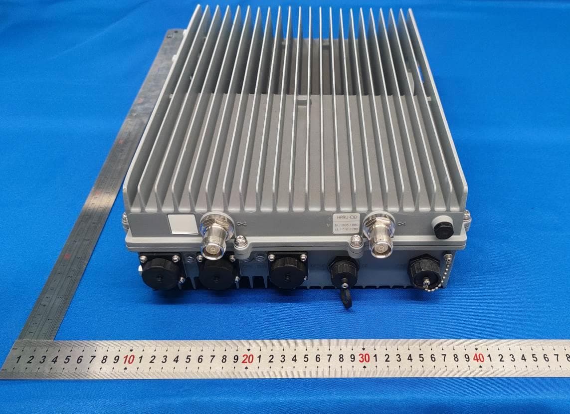
Click to zoom
Application Details
- Equipment Class
- B2I - Part 20 Industrial Booster (CMRS)
- Date of Grant
- Jun 02, 2022
- Application Purpose
- Original Equipment
- Date of Application
- Jun 02, 2022
- Equipment Note
- Remote Unit
- Frequency Range
- 2110.00000000 - 2200.00000000
- Country
- China
Documents & Files
Document Text
Text extracted from the exhibit documents filed with the FCC. Open a document above to read the original.
Users Manual
H2 HIGH POWER Dual Band Digital Radios 43dBm per Band Passive Cooling INSTALLATION MANUAL Remote Unit iDAS-R311 HIGH POWER 43dBm Dual Band Digital Radio © Sunwave IM_CF_H2 v1.0.0 | 2 of 47 Contact us today: www.sunwave.com [email protected] Revision History Revision Number Revision Date Summary of Changes Author 1.0.0 1 st November 2021 Initial Release Shuochao Zheng Copyright © 2022 Sunwave All rights reserved. No part of this publication may be reproduced, transmitted, transcribed, stored in a retrieval system, or translated into any language, in any form or by any means, electronic, mechanical, photocopying, recording, or otherwise, without prior written permission from Sunwave. All copyright, confidential information, patents, design rights, and all other intellectual property rights of whatsoever nature contained herein are and shall remain the sole and exclusive property of Sunwave. The information furnished herein is believed to be accurate and reliable. However, no responsibility is assumed by Sunwave for its use or any infringements of patents or other rights of third parties resulting from its use. The Sunwave and CrossFire names and logos are trademarks or registered trademarks of Sunwave. All other trademarks are the property of their respective owners. HIGH POWER 43dBm Dual Band Digital Radio © Sunwave IM_CF_H2 v1.0.0 | 3 of 47 Contact us today: www.sunwave.com [email protected] Content Overview.................................................................................................................................................................................................5 Preface .................................................................................................................................................................................... 8 Safety Instructions .............................................................................................................................................................. 8 Site Considerations ......................................................................................................................................................... 9 Environmental Considerations ........................................................................................................................................ 9 DC Power Connections .................................................................................................................................................. 10 Warning Marks .............................................................................................................................................................. 11 Unpacking and Inspecting ............................................................................................................................................. 12 Inspecting the Packing Container ................................................................................................................................. 12 Unpacking the Device ................................................................................................................................................... 12 Verifying the Contents .................................................................................................................................................. 12 Inspecting the Device .................................................................................................................................................... 12 Installation Preparation ................................................................................................................................................ 13 Site Investigation ........................................................................................................................................................... 13 Installation Tools ........................................................................................................................................................... 13 Torque Settings ............................................................................................................................................................. 13 Clearance ...................................................................................................................................................................... 13 Installation of the A2 ............................................................................................................................................................. 14 Mount the A2 in the Rack ................................................................................................................................................. 15 A2 Accessories ............................................................................................................................................................... 15 Attach A2 Handle .......................................................................................................................................................... 16 Attach Sliding Rails and A2 to Rack ............................................................................................................................... 16 Fan Installation .............................................................................................................................................................. 17 Connect Power and Ground Cable to A2 ...................................................................................................................... 18 DC Power Connections ...................................................................................................................................................... 19 Attach Handle to A2 .....................................................................................................................................................…
Text truncated - open the document above for the full version.
Attestation Statements
Sunwave Communications Co., Ltd ADD: 581 Huoju Avenue,Binjiang District Hangzhou China TEL: +86-571-86704493 FAX: +86-571 -88859966 E-mail: [email protected] Attestation Letter Date : 2022-4-14 To: FEDERAL COMMUNICATIONS COMMISSIONS Authorization and Evaluation Division 7435 Oakland Mills Road Columbia, MD 21046 Dear Sir or Madam: Pursuant to the provisions of KDB 935210 D02, Section IV INDUSTRIAL (PART 20) SIGNAL BOOSTER SPECIFIC REQUIREMENTS (d), I declare that Warning label message will be also shown in online and point-of-sale marketing marketing materials and on outside packaging of device and User’ manual and permanently affixed to EUT Booster Warning Label Sincerely Yours, Signature: Typed or Printed Name:Ren Ailin Title:Manager
Cover Letter(s)
QA-FR-170-B SunwaveCommunicationsCo.,Ltd ADD:581HuojuAvenue,BinjiangDistrictHangzhouChina TEL:+86-571-86704493 FAX:+86-571-88859966 E-mail:[email protected] FCCAuthorization Date:2022-04-07 FEDERALCOMMUNICATIONSCOMMISSION AuthorizationandEvaluationDivision 7435OaklandMillsRoad Columbia,MD21046 Subject:AgentAuthorization Towhomitmayconcern: We,SunwaveCommunicationsCo.,Ltd,HerebyauthorizesChinaCertificationICTCo., Ltd(Dongguan)toactonitsbehalfinallmattersrelatingtoapplicationforEquipment authorization,includingthesigningofalldocumentsrelatingtothesematters.Allacts carriedoutbyChinaCertificationICTCo.,Ltd(Dongguan)onourbehalfshallhavethe sameeffectasourownaction. We,theundersigned,herebycertifythatwearenotsubjecttoadenialoffederalbenefits, thatincludesFCCbenefits,pursuanttoSection5301oftheAnti-DrugAbuseActof1988, 21U.S.C.862. Thisauthorizationisvaliduntilfurtherwrittennoticefromtheapplicant. SincerelyYours, Client’ssignature PrintedName:RenAilin Title:Manager
Cover Letter(s)
QA-FR-171-A SunwaveCommunicationsCo.,Ltd ADD:581HuojuAvenue,BinjiangDistrictHangzhouChina TEL:+86-571-86704493 FAX:+86-571-88859966 E-mail:[email protected] FCCConfidentialAuthorization Date:2022-04-07 FEDERALCOMMUNICATIONSCOMMISSIONS AuthorizationandEvaluationDivision 7435OaklandMillsRoad Columbia,MD21046 Subject:ConfidentialityRequestregardingapplicationforcertificationofFCCID:2AEJ4R31166E InaccordancewithSections0.457and0.459oftheCommission’sRules,(SunwaveCommunications Co.,Ltd)herebyrequestslong-termconfidentialtreatmentofinformationaccompanyingthisapplication asoutlinedbelow: BlockDiagram Schematics OperationDescription PartsList/Tuneupprocedure(forlicenseddevices) Theabovematerialscontainproprietaryandconfidentialinformationnotcustomarilyreleasedtothe public.Thepublicdisclosureofthesematerialsprovidesunjustifiedbenefitstoitscompetitorsinthe market. Sincerely, Signature: Printedname:RenAilin Title:Manager
Cover Letter(s)
SunwaveCommunicationsCo., Ltd ADD: 581 Huoju Avenue,BinjiangDistrictHangzhouChina TEL: +86-571-86704493 FAX: +86-571-88859966 E-mail:[email protected] AuthorizationLetter Date: 2022-04-07 FEDERAL COMMUNICATIONS COMMISSION Authorization and Evaluation Division 7435 Oakland Mills Road Columbia, MD 21046 Subject: Professional Installation Statement for FCC ID: 2AEJ4R31166E Dear Sir or Madam, Please be notified that we, the undersigned, state that our device requires professional installation based on the following reasons: 1 this device will not be sold to the general public, it will be sold to dealers only. 2 this device requires controlled installation location by professional installers. 3 the device requires professional configuration for use. These statements above apply to the following project: Product name: Remote Unit Models: iDAS-R311 Please contact me if you have any question. Sincerely, Signature: PrintedName:Ren Ailin Title: Manager
External Photos
EXHIBIT B - EUT EXTERNAL PHOTOGRAPHS Ant 1 port Ant 2 port
ID Label/Location Info
Serial: iDAS-R31113BEP XXXXXXXXXX MFG Date: DD-MM-YYYY XXXXXXXXXXXXXX Integrated Distributed Antenna System Remote Unit H2RU-OD-2-AC Model: iDAS-R311 Input: 100-240V~ 3A 50/60Hz Manufacturer: Sunwave Communications Co., Ltd. Address: 581,Huoju Avenue, Binjiang District, Hangzhou,P.R.China,310053 ITE E504646 This device complies with Part 15 of the FCC Rules. Operation is subject to the following two conditions: (1) this device may not cause harmful interference, and (2) this device must accept any interference received, including interference that may cause undesired operation. WARNING! This is NOT a CONSUMER device. It is designed for installation by FCC LICENSEES and QUALIFIED INSTALLERS. You MUST have an FCC LICENSE or express consent of an FCC License to operate this device. Unauthorized use may result in significant forfeiture penalties, including penalties in excess of $100,000 for each continuing violation. FCC ID: 2AEJ4R31166E
Internal Photos
EXHIBIT C - EUT INTERNAL PHOTOGRAPHS
RF Exposure Info
China Certification ICT Co., Ltd (Dongguan) Report No.: CR22020015-00 Page 38 of 38 6. RF EXPOSURE EVALUATION 6.1 Maximum Permissible Exposure (MPE) 6.1.1 Applicable Standard According to subpart §1.1310, systems operating under the provisions of this section shall be operated in a manner that ensures that the public is not exposed to radio frequency energy level in excess of the Commission’s guidelines. 6.1.2 Limits Maximum Permissible Exposure (MPE) (§1.1310, §2.1091) (B) Limits for General Population/Uncontrolled Exposure Frequency Range (MHz) Electric Field Strength (V/m) Magnetic Field Strength (A/m) Power Density (mW/cm 2 ) Averaging Time (minutes) 0.3–1.34 614 1.63 *(100) 30 1.34–30 824/f 2.19/f *(180/f²) 30 30–300 27.5 0.073 0.2 30 300–1500 / / f/1500 30 1500–100,000 / / 1.0 30 f = frequency in MHz; * = Plane-wave equivalent power density; According to §1.1310 and §2.1091 RF exposure is calculated. 6.1.3 Calculated Formulary: Predication of MPE limit at a given distance S = PG/4R² = power density (in appropriate units, e.g. mW/cm 2 ); P = power input to the antenna (in appropriate units, e.g., mW); G = power gain of the antenna in the direction of interest relative to an isotropic radiator, the power gain factor, is normally numeric gain; R = distance to the center of radiation of the antenna (appropriate units, e.g., cm); 6.1.4 Calculated Data Frequency Band (MHz) Maximum Tune-up Conducted Output Power (dBm) Antenna Gain (dBi) Evaluation Distance (cm) Power Density (mW/cm 2 ) MPE Limit (mW/cm 2 ) 2110-2200 47 12 400 0.40 1 Result:The device meet FCC MPE requirement at 400 cm distance. =====END OF REPORT=====
Test Report
TEST REPORT Applicant: Sunwave Communications Co.,Ltd. Address: 581 Huoju Avenue,Binjiang District,Hangzhou,China FCC ID: 2AEJ4R31166E Product Name: Remote Unit Model Number: iDAS-R311 Standard(s): 47 CFR Part 27 47 CFR Part 20.21 ANSI C63.26-2015 KDB 935210 D05 Indus Booster Basic Meas v01r04 The above equipment has been tested and found compliant with the requirement of the relative standards by China Certification ICT Co., Ltd (Dongguan) Report Number: CR22020015-00 Date Of Issue: 2022-05-25 Reviewed By: Sun Zhong Title: Manager Test Laboratory: China Certification ICT Co., Ltd (Dongguan) No. 113, Pingkang Road, Dalang Town, Dongguan, Guangdong, China Tel: +86-769-82016888 China Certification ICT Co., Ltd (Dongguan) Report No.: CR22020015-00 Page 2 of 38 Test Facility The Test site used by China Certification ICT Co., Ltd (Dongguan) to collect test data is located on the No. 113, Pingkang Road, Dalang Town, Dongguan, Guangdong, China. The lab has been recognized as the FCC accredited lab under the KDB 974614 D01 and is listed in the FCC Public Access Link (PAL) database, FCC Registration No. : 442868, the FCC Designation No. : CN1314. The lab has been recognized by Innovation, Science and Economic Development Canada to test to Canadian radio equipment requirements, the CAB identifier: CN0123. Declarations China Certification ICT Co., Ltd (Dongguan) is not responsible for the authenticity of any test data provided by the applicant. Data included from the applicant that may affect test results are marked with a triangle symbol “▲”. Customer model name, addresses, names, trademarks etc. are not considered data. Unless otherwise stated the results shown in this test report refer only to the sample(s) tested. This report cannot be reproduced except in full, without prior written approval of the Company. This report is valid only with a valid digital signature. The digital signature may be available only under the Adobe software above version 7.0. This report may contain data that are not covered by the accreditation scope and shall be marked with an asterisk “★”. China Certification ICT Co., Ltd (Dongguan) Report No.: CR22020015-00 Page 3 of 38 CONTENTS TEST FACILITY ............................................................................................................................................................ 2 DECLARATIONS ........................................................................................................................................................... 2 1. GENERAL INFORMATION .................................................................................................................................. 4 1.1 PRODUCT DESCRIPTION FOR EQUIPMENT UNDER TEST (EUT) ............................................................................... 4 1.2 DESCRIPTION OF TEST CONFIGURATION ................................................................................................................ 5 1.2.4 Radiated Spurious Emissions Block Diagram of Test Setup ......................................................................... 6 1.3 MEASUREMENT UNCERTAINTY ............................................................................................................................. 7 2. SUMMARY OF TEST RESULTS .......................................................................................................................... 8 3. REQUIREMENTS AND TEST PROCEDURES ................................................................................................... 9 3.1 AGC THRESHOLD LEVEL ....................................................................................................................................... 9 3.1.1 Applicable Standard ...................................................................................................................................... 9 3.1.2 TEST PROCEDURE ............................................................................................................................................... 9 3.1.3 EUT SETUP......................................................................................................................................................... 9 3.2 OUT-OF-BAND REJECTION .................................................................................................................................. 10 3.2.1 Applicable Standard .................................................................................................................................... 10 3.2.2 TEST PROCEDURE ............................................................................................................................................. 10 3.2.3 EUT SETUP....................................................................................................................................................... 10 3.3 MEAN OUTPUT POWER AND AMPLIFIER GAIN .................................................................................................... 11 3.3.1 Applicable Standard .................................................................................................................................... 11 3.3.2 Test Procedure ............................................................................................................................................. 11 3.3.3 EUT SETUP....................................................................................................................................................... 11 3.4 OCCUPIED BANDWIDTH AND INPUT-VERSUS-OUTPUT SIGNAL COMPARISON ..................................................... 12 3.4.1 Applicable Standard .................................................................................................................................... 12 3.4.2 Test Procedure ............................................................................................................................................. 12 3.4.3 EUT SETUP.......…
Text truncated - open the document above for the full version.
Test Setup Photos
EXHIBIT D - TEST SETUP PHOTOGRAPHS Ra diated Emissions Below 1G View Radiated Emissions Above 1G rear View
Contact Information
Applicant
Ren Ailin
Test Firm
CHINA CERTIFICATION ICT CO., LTD (DONGGUAN)Tanie Ou
[email protected]0086 0769 86858888
Technical Specifications
| # | Rule Parts | Frequency Range | Power Output | Emission | Tolerance |
|---|---|---|---|---|---|
| 2 | 27 | 2.11 GHz - 2.20 GHz | 38.11 W | W7D | Amp |
Other Applications from Sunwave Communications Co., Ltd
2AEJ4R22208
Aug 12, 2024Remote Unit
Equipment Class
B9B - Part 90 Class B Industrial Booster (non-SMR)
2AEJ4R22207
Aug 06, 2024Remote Unit
Equipment Class
B9B - Part 90 Class B Industrial Booster (non-SMR)
2AEJ4R2220708
Apr 21, 2021Remote Unit
Equipment Class
B9B - Part 90 Class B Industrial Booster (non-SMR)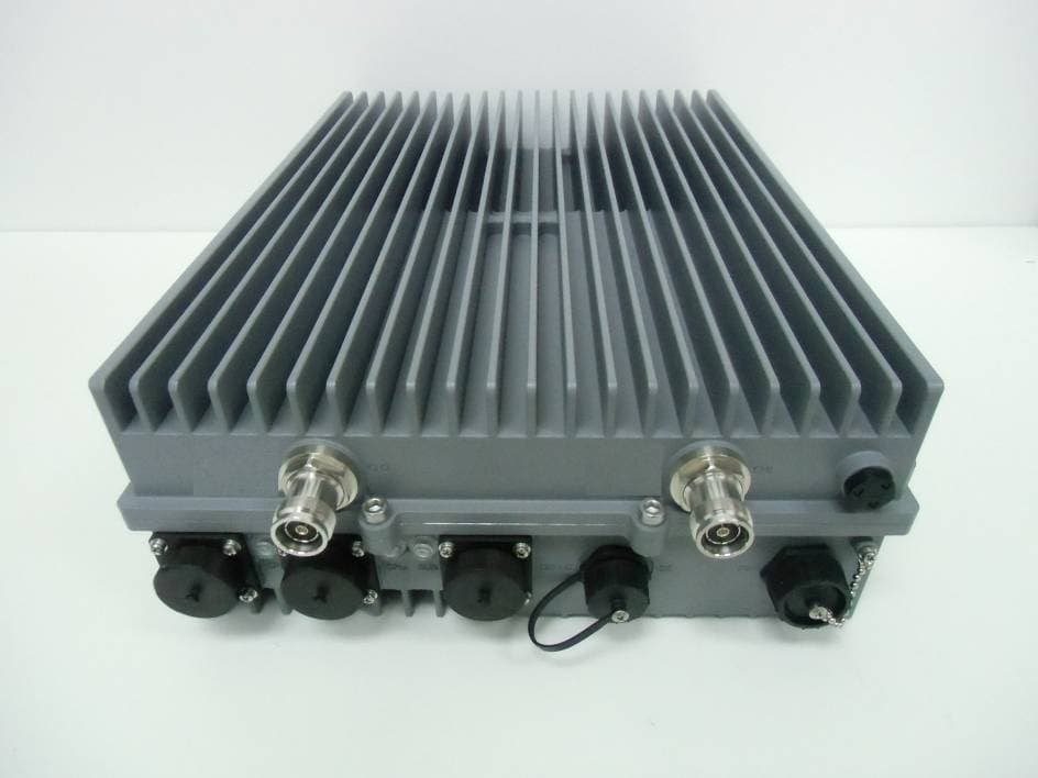
2AEJ4R211CD
Jun 25, 2015Remote Unit
Equipment Class
B2I - Part 20 Industrial Booster (CMRS)
2AEJ4R2115W
Jun 04, 2015Remote Unit
Equipment Class
B2I - Part 20 Industrial Booster (CMRS)