2AEKCPH5Y0U2Two way radio
ZTE TRUNKING TECHNOLOGY CORPORATION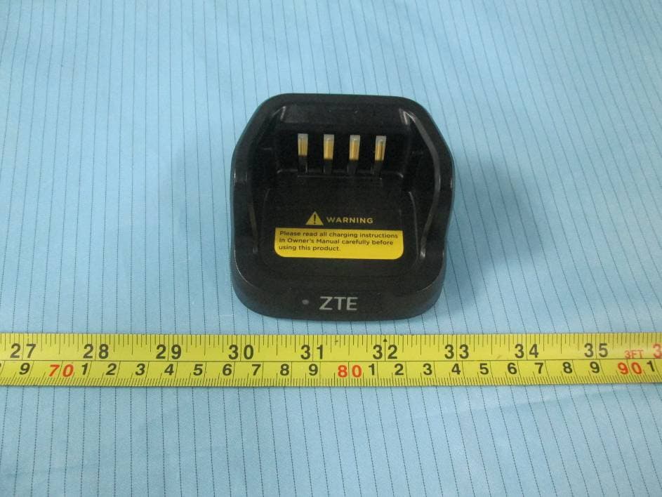
Click to zoom
Application Details
- Equipment Class
- TNF - Licensed Non-Broadcast Transmitter Held to Face
- Date of Grant
- Jul 30, 2015
- Application Purpose
- Original Equipment
- Date of Application
- Jul 30, 2015
- Equipment Note
- Two way radio
- Frequency Range
- 450.00000000 - 520.00000000
- Country
- China
Documents & Files
Document Text
Text extracted from the exhibit documents filed with the FCC. Open a document above to read the original.
Users Manual
Legal Information Copyright © 2015 ZTE Trunking Technology Corporation All rights reserved. No part of this publication may be excerpted, reproduced, translated or utilized in any form or by any means, electronic or mechanical, including photocopying and microfilm, without the prior written permission of ZTE Trunking Technology Corporation. The manual is published by ZTE Trunking Technology Corporation. We reserve the right to make modifications on print errors or update specifications without prior notice. The information on the package is only for your reference. Images are for your reference only. Please check the product model before purchasing. 12 Install the Antenna Turn off the HT, place the antenna into the installation hole, and turn the antenna clockwise. To remove the antenna, turn the antenna anticlockwise. Before removing the antenna, ensure that you have turned off the HT and removed the universal interface cover. To replace the antenna, use a specified antenna to replace the old one. Otherwise, your HT may be damaged. Install the Belt Clip Align the screw holes on the belt clip with those on the rear side of the HT, and fasten the belt clip with screws. Install the Universal Interface Cover The universal interface is on the antenna side of the HT. It connects an accessory to your HT. Insert the universal interface cover fastener into the universal interface slot. Press the cover, so that it is fastened to the RF interface. Tighten the screw clockwise to fix the interface cover to the HT. To remove the interface cover, press the cover, and loosen the screw anticlockwise. Lift up the cover, and slide it down. Turn On the HT Turn the volume/power knob clockwise until you hear a click sound. The HT gives a short beep sound, indicating that the HT is successfully turned on. Note: If you disable the tone/prompt function, no beep sound can be heard (for details, refer to the Enable or Disable the Tone/Prompt Function section). If your HT cannot be turned on, check the battery. Verify that the battery is charged and properly installed. If your HT still cannot be turned on, contact your agent. To turn off the HT, turn the knob anticlockwise until you hear a click sound. Adjust the Volume Turn the volume knob clockwise to turn up the volume. To turn down the volume, turn the knob anticlockwise. HT Control Please read the following carefully: • HT control options • Programmable buttons • PTT button HT Control Options Getting Started Please read the following carefully: How to use this manual... What can you get from your agent or system administrator... How to use this manual? Please refer to each chapter for the details. What can you get from your agent or system administrator? You may ask your agent or system administrator about the following issues: • Does your Handheld Transceiver (HT) have default channels? • Which buttons can be used to access other functions? • Which optional accessories do you need? This manual describes basic operations on an HT. Your agent or system administrator may have customized your HT to address your special needs. For details, contact your agent or system administrator. Ready to Use the HT Perform the following steps to assemble your HT: Charge the battery. Install the battery. Install the antenna. Install the belt clip. Install the universal interface cover. Turn on the HT. Adjust the volume. Charge the Battery The HT is powered by a Li-Ion battery. To protect the battery from damage and comply with the warranty conditions, you can use only the charger provided with the battery for charging. To maximize battery performance, it is recommended to charge the battery for 14 to 16 hours before the first use. Install the Battery Align the battery with the battery slot on the rear side of the HT. Push the battery into the slot until it is fastened. Before removing the battery, turn off the HT first. Press the battery fastener, and then remove the battery. Note: The button marked with an asterisk means a programmable button. Programmable Buttons Your agent can set a programmable button to a shortcut button for a function or channel or call group in accordance with the duration for which the button is pressed: • Press: means pressing a button and immediately releasing the button. • Press and hold: means pressing a button and holding the button for a pre-programmed duration (between 1 second and 3.75 seconds). Assignable HT Functions • Emergency call: initiates or cancels an emergency alarm or call. • Monitoring: monitors any activities in a selected analog channel. • One-press call: initiates a predefined private call, group call, or short message by pressing one button. Select a Channel, a User ID, or a Call Group ID After selecting a zone (if there are multiple zones), you can turn the channel selection knob to select a channel, a user ID, or a call group ID. Receive and Respond to a Call After selecting a channel, a user ID, or a call group ID, you can receive or respond to a call. When the HT is transmitting signals, the LED indicator is lit red. When the HT is receiving signals, the LED indicator is lit green. Receive and Respond to a Group Call To receive a call from a user group, you must configure the call group on the HT. 1. Verify that the LED indicator is lit green. 2. Hold the HT vertically, and keep it about 1 to 2 inches (2.5 to 5.0 cm) away from your mouth. If the "idle channel prompt" function is enabled, when the transmitting HT releases the PTT button, you will hear a short prompt sound, indicating that the channel becomes idle, and you can respond. 3. Press the PTT button to respond to the call. The LED indicator is lit red. 4. Wait until the call admission tone (if activated) ends, and speak to the microphone. 5. Release the PTT button to listen to other members in the call. 6. If no one talks within a specified period, the call ends. Receive and Respond to a Private Call A private call means a call that a single HT initiates to another H…
Text truncated - open the document above for the full version.
Attestation Statements
ZTE TRUNKING TECHNOLOGY CORPORATION 4/F, R&D Building 1, ZTE Industrial Park, LiuXian Road, Xili, Nanshan District, Shenzhen, P. R. China Tel: 0755-2677463 Fax: 0755-26774670 2015-07-27 Attestation FEDERAL COMMUNICATIONS COMMISSIONS Authorization and Evaluation Division 7435 Oakland Mills Road Columbia, MD 21046 Dear Sir/Madam, We, ZTE TRUNKING TECHNOLOGY CORPORATION hereby declare that our product: Two way radio FCC ID: 2AEKCPH5Y0U2 is capable of supporting a voice channel and a minimum data rate of 4800 bits per second per 6.25 KHz of channel bandwidth. DMR interphone’s bandwidth is 12.5 KHz, and it has a double time slot, one is the speech time slot, one is the data time slot, just language sequence is satisfied with 4800 BPS / 6.25 KHz. The technical data supplied with this application, having been reviewed by me and taken by the ZTE TRUNKING TECHNOLOGY CORPORATION accessory and EME Teams is hereby duly certified. Signature: Yanchun Ma Manager
Cover Letter(s)
ZTETI主UNKlNGTECHNOLOGY CORPORATlON 4且.. , R&D Building 1, ZTE Industrial Park, LiuXian Road, Xi1i, Nanshan District, Shenzhen, P. R. China Tel: 0755-2677463 F皿0755-26774670 FCC Confidential Authorization 07/06/2015 FEDERAL COMMUNICATIONS COMMISSIONS Authorization and Evaluation Division 7435 Oakland Mills Road Columbia , MD 21046 Subjec t: Confidentiality Request regarding application for c巳rtificationof FCC ID: 2AEKCPH5YOU2 In accordance with S巳ctions0.457 and 0.459 ofthe Commission's Rules, (ZTE TRUNKING TECI卦WLOGYCORPORATION) Wirel巳ssInc. hereby requests long- term confidential treatment of information ac∞mpanying this application as outlined below • Block Diagram • Schematics • Operation Description • Parts Lis tITune up procedure (for licensed devices) • The above materials contain proprietary and confidential information not customarily released to也epublic. The public disc10sure of these materials provides u时ustified benefits to its competitors in由em缸ket Sincerely, Signature: YanchunMa Manager lC(lt\,d比j)4ttnd-切1f.Ì.i萨
External Photos
EXHIBIT B - EUT EXTERNAL PHOTOGRAPHS EUT – All View EUT – Front View EUT – Rear View EUT – Top View EUT – Bottom View EUT – Left Side View EUT – Right Side View EUT – Charger Front View EUT – Charger Rear View EUT – Charger Top View EUT – Charger Bottom View EUT – Charger Left Side View EUT – Charger Right Side View EUT – Adapter View EUT – Adapter Label View EUT – Charger Label View
ID Label/Location Info
EXHIBIT A - FCC ID LABELING AND LOCATION FCC ID Label Proposed FCC ID Label Location The label shown shall be permanently affixed at a conspicuous location on the device and be readily visible to the user at the time purchase (Labeling requirements per 2.925) Label here
Internal Photos
EXHIBIT C - EUT INTERNAL PHOTOGRAPHS EUT – Cover off View 1 EUT – Cover off View 2 EUT – Cover off View 3 EUT – Cover off View 4 EUT – Cover off View 5 EUT – Main Board Top View EUT – Main Board Bottom View EUT –Charger Cover off View 1 EUT – Charger Cover off View 2 EUT – Charger Main Board Top View EUT – Charger Main Board Bottom View EUT – IC Chip View EUT – Antenna View EUT – Antenna Port View EUT – Battery Top View EUT – Battery Bottom View EUT – Battery Label View
RF Exposure Info
Note: This test report is prepared for the customer shown above and for the device described herein. It may not be duplicated or used in part without prior written consent from Bay Area Compliance Laboratories Corp. SAR EVALUATION REPORT For ZTE TRUNKING TECHNOLOGY CORPORATION 4/F, R&D Building 1, ZTE Industrial Park, LiuXian Road, Xili, Nanshan District, Shenzhen, P. R. China FCC ID: 2AEKCPH5Y0U2 Report Type: Original Report Product Type: Two way radio Test Engineer: Wilson Chen Report Number: RSZ150625005-20A Report Date: 2015-07-21 Reviewed By: Bell Hu SAR Engineer Prepared By: Bay Area Compliance Laboratories Corp. (Shenzhen) 6/F, the 3rd Phase of WanLi Industrial Building, ShiHua Road, FuTian Free Trade Zone Shenzhen, Guangdong, China Tel: +86-755-33320018 Fax: +86-755-33320008 www.baclcorp.com.cn Bay Area Compliance Laboratories Corp. (Shenzhen) Report No: RSZ150625005-20A SAR Evaluation Report 2 of 63 Attestation of Test Results EUT Information Company Name ZTE TRUNKING TECHNOLOGY CORPORATION EUT Description Two way radio FCC ID 2AEKCPH5Y0U2 Model Number Test model: PH520 U(2) Test Date 2015-06-28 Frequency (MHz) Mode Max. SAR Level(s) Reported Limit (W/Kg) 450-512 Digital 12.5kHz Face up: 1.848 W/kg Body-Back: 4.120 W/kg 8.0 Analog 12.5kHz Face up: 2.104 W/kg (Corrected by multiplying 50%) Body worn: 4.090 W/kg (Corrected by multiplying 50%) Applicable Standards ANSI / IEEE C95.1: 2005 IEEE Standard for Safety Levels with Respect to Human Exposure to Radio Frequency Electromagnetic Fileds,3 kHz to 300 GHz. ANSI / IEEE C95.3: 2002 IEEE Recommended Practice for Measurements and Computations of Radio Frequency Electromagnetic Fields With Respect to Human Exposure to SuchFields,100 kHz—300 GHz. IEEE1528:2013 IEEE Recommended Practice for Determining the Peak Spatial-Average Specific Absorption Rate (SAR) in the Human Head from Wireless Communications Devices: Measurement Techniques KDB procedures KDB 447498 D01 v05r02: Mobile and Portable Devices RF Exposure Procedures and Equipment Authorization Policies. KDB 865664 D01v01r03: SAR measurement 100 MHz to 6 GHz v01. KDB 643646D01 v01r01: SAR test Reduction Considerations for Occupational PTT Radios. Note: This wireless device has been shown to be capable of compliance for localized specific absorption rate (SAR) for Occupational /Controlled Exposure limits specified in ANSI/IEEE Standards and has been tested in accordance with the measurement procedures specified in IEEE 1528-2013 and RF exposure KDB procedures. The results and statements contained in this report pertain only to the device(s) evaluated. Bay Area Compliance Laboratories Corp. (Shenzhen) Report No: RSZ150625005-20A SAR Evaluation Report 3 of 63 TABLE OF CONTENTS DOCUMENT REVISION HISTORY ......................................................................................................................... 4 EUT DESCRIPTION .................................................................................................................................................... 5 TECHNICAL SPECIFICATION ......................................................................................................................................... 5 REFERENCE, STANDARDS, AND GUILDELINES ............................................................................................... 6 SAR LIMITS ................................................................................................................................................................. 7 FACILITIES .................................................................................................................................................................. 8 DESCRIPTION OF TEST SYSTEM .......................................................................................................................... 9 EQUIPMENT LIST AND CALIBRATION ............................................................................................................. 16 EQUIPMENTS LIST & CALIBRATION INFORMATION .................................................................................................... 16 SAR MEASUREMENT SYSTEM VERIFICATION .............................................................................................. 17 LIQUID VERIFICATION ............................................................................................................................................... 17 SYSTEM ACCURACY VERIFICATION ........................................................................................................................... 19 SAR SYSTEM VALIDATION DATA ..................................................................................................................... 20 EUT TEST STRATEGY AND METHODOLOGY ................................................................................................. 24 TEST POSITIONS FOR DEVICE OPERATING NEXT TO A PERSON’S EAR........................................................................ 24 CHEEK/TOUCH POSITION ........................................................................................................................................... 25 EAR/TILT POSITION ................................................................................................................................................... 25 TEST POSITIONS FOR BODY-WORN AND OTHER CONFIGURATIONS .............................................................................. 26 SAR EVALUATION PROCEDURE ................................................................................................................................. 27 TEST METHODOLOGY ................................................................................................................................................. 27 CONDUCTED OUTPUT POWER MEASUREMENT ........................................................................................... 28 PROVISION APPLICABLE ...........................................…
Text truncated - open the document above for the full version.
Test Report
Note: This test report is prepared for the customer shown above and for the equipment described herein. It may not be duplicated or used in part without prior written consent from Bay Area Compliance Laboratories Corp. FCC PART 90 TEST REPORT For ZTE TRUNKING TECHNOLOGY CORPORATION 4/F, R&D Building 1, ZTE Industrial Park, LiuXian Road, Xili, Nanshan District, Shenzhen, P. R. China FCC ID: 2AEKCPH5Y0U2 Report Type: Original Report Product Type: Two way radio Test Engineer: William Li Re port Number: RSZ150625005-00 Re port Date: 2015-07-17 Reviewed B y: Jimmy Xiao RF Engineer Prepared By: Bay Area Compliance Laboratories Corp. (Shenzhen) 6/F, the 3rd Phase of WanLi Industrial Building, ShiHua Road, FuTian Free Trade Zone Shenzhen, Guangdong, China Tel: +86-755-33320018 Fax: +86-755-33320008 www.baclcorp.com.cn Bay Area Compliance Laboratories Corp. (Shenzhen) Report No.: RSZ150625005-00 FCC PART 90 Page 2 of 34 TABLE OF CONTENTS GENERAL INFORMATION ....................................................................................................................................... 4 PRODUCT DESCRIPTION FOR EQUIPMENT UNDER TEST (EUT) ..................................................................................... 4 OBJECTIVE ................................................................................................................................................................... 4 RELATED SUBMITTAL(S)/GRANT(S) ............................................................................................................................. 4 TEST METHODOLOGY .................................................................................................................................................. 4 TEST FACILITY ............................................................................................................................................................. 5 SYSTEM TEST CONFIGURATION .......................................................................................................................... 6 DESCRIPTION OF TEST CONFIGURATION ...................................................................................................................... 6 EQUIPMENT MODIFICATIONS ....................................................................................................................................... 6 SUPPORT EQUIPMENT LIST AND DETAILS .................................................................................................................... 6 BLOCK DIAGRAM OF TEST SETUP ................................................................................................................................ 6 SUMMARY OF TEST RESULTS ............................................................................................................................... 7 FCC §1.1307(b) & §2.1093 - RF EXPOSURE ............................................................................................................. 8 APPLICABLE STANDARD .............................................................................................................................................. 8 FCC §2.1046 & §90.205 - RF Output Power ............................................................................................................... 9 APPLICABLE STANDARD .............................................................................................................................................. 9 TEST PROCEDURE ........................................................................................................................................................ 9 TEST EQUIPMENT LIST AND DETAILS ........................................................................................................................... 9 TEST DATA .................................................................................................................................................................. 9 FCC §2.1047 & §90.207 - MODULATION CHARACTERISTIC .......................................................................... 11 APPLICABLE STANDARD ............................................................................................................................................ 11 TEST EQUIPMENT LIST AND DETAILS ......................................................................................................................... 11 TEST PROCEDURE ...................................................................................................................................................... 11 TEST DATA ................................................................................................................................................................ 11 FCC §2.1049 & §90.209 & §90.210 – OCCUPIED BANDWIDTH & EMISSION MASK ................................... 16 APPLICABLE STANDARD ............................................................................................................................................ 16 TEST EQUIPMENT LIST AND DETAILS ......................................................................................................................... 17 TEST PROCEDURE ...................................................................................................................................................... 17 TEST DATA ................................................................................................................................................................ 18 FCC §2.1051 & §90.210 - SPURIOUS EMISSIONS AT ANTENNA TERMINALS ............................................ 23 APPLICABLE STANDARD ............................................................................................................................................ 23 TEST EQUIPMENT LIST AND DETAILS ......................................................................................................................... 24 TEST PROCEDURE .…
Text truncated - open the document above for the full version.
Test Setup Photos
EXHIBIT D - TEST SETUP PHOTOGRAPHS Transmitting Radiated Emissions View (Below 1 GHz) Transmitting Radiated Emissions View (Above 1 GHz)
Contact Information
Applicant
Zhan Zhu
Test Firm
Bay Area Compliance Laboratory Corp. (Shenzhen)John Chan
Technical Specifications
| # | Rule Parts | Frequency Range | Power Output | Emission | Tolerance |
|---|---|---|---|---|---|
| 2 | 9 | 450 MHz - 520 MHz | 5 W | 7K70FXD | 2.5 ppm |
Other Applications from ZTE TRUNKING TECHNOLOGY CORPORATION
2AEKCPR800U1
Jan 27, 2016DIGITAL REPEATER
Equipment Class
TNB - Licensed Non-Broadcast Station Transmitter
2AEKCPH5X0VHF
Jul 30, 2015Two way radio
Equipment Class
TNF - Licensed Non-Broadcast Transmitter Held to Face
2AEKCPH5Y0U1
Jul 29, 2015LinX 200
Equipment Class
TNF - Licensed Non-Broadcast Transmitter Held to Face