2AEZR-SRBRSELFR1SRBRS ELF Badge
Amazon.com Services LLC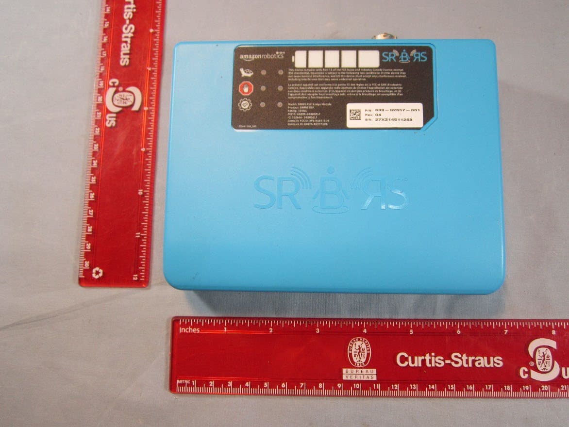
Click to zoom
Application Details
- Equipment Class
- DXX - Part 15 Low Power Communication Device Transmitter
- Date of Grant
- Dec 18, 2022
- Application Purpose
- Original Equipment
- Date of Application
- Dec 01, 2022
- Equipment Note
- SRBRS ELF Badge
- Frequency Range
- 925.00000000 - 925.00000000
- Company
- Amazon.com Services LLC
- Country
- United States
Documents & Files
Document Text
Text extracted from the exhibit documents filed with the FCC. Open a document above to read the original.
Users Manual
SRBRS Hardware Manual 1 Title: SRBRS Safety System Hardware Manual Date: November 07, 2022 Type: Hardware Manual Associated Documents: Document Rev: 01 SRBRS Safety System Hardware Manual For Amazon Fulfillment Services Only 2 SRBRS Hardware Manual Contents Title: SRBRS Safety System Hardware Manual ................................................................................................. 1 CONTENTS ....................................................................................................................................................... 2 INTRODUCTION ................................................................................................................................................ 3 Manual Scope .................................................................................................................................................. 3 Intended Audience ........................................................................................................................................... 3 Document Conventions ................................................................................................................................... 3 SAFETY INFORMATION ..................................................................................................................................... 5 Lithium Ion Battery Safety Warnings ............................................................................................................... 5 Radio Module Faceplate Information .............................................................................................................. 6 Power REquirement ......................................................................................................................................... 6 Environmental Specifications .......................................................................................................................... 7 Lifecycle 7 Operator Controls ............................................................................................................................................ 7 Powering on the SRBRS Safety System ............................................................................................................... 7 Activating the SRBRS Safety System .................................................................................................................... 7 Powering off the SRBRS Safety System ............................................................................................................... 8 REGULATORY COMPLIANCE ............................................................................................................................. 9 North America 9 SRBRS Hardware Manual 3 Introduction MANUAL SCOPE This manual addresses the hardware and specifications for the AR SRBRS Safety System models. SRBRS is one component of an AR Mobile-Robotic Fulfillment System™ (MFS) and does not operate independently of an AR MFS installation. The reader is advised to become familiar with the basics of the AR MFS prior to reading this manual. Note: Operational and Maintenance procedures are not covered in this document. INTENDED AUDIENCE Information in this document is intended for trained Amazon employees. DOCUMENT CONVENTIONS The following typographical conventions and icons are used in Amazon Robotics documentation: Indicates an imminently hazardous situation which, if not avoided, will result in death or serious injury. Indicates a potentially hazardous situation which, if not avoided, could result in death or serious injury. Indicates a potentially hazardous situation which, if not avoided, may result in minor or moderate injury. Indicates a statement of company policy directly or indirectly related to the safety of personnel or protection of property. This image corresponds with an entrapment hazard for your torso. This image corresponds with a crushing hazard for your leg. This image corresponds with a crushing hazard for your arm. This image corresponds with an electrical hazard. This image corresponds with a tip or overbalance hazard. This image corresponds with a crushing or pinching hazard for your fingers. This image corresponds with a hand entanglement / rotating gears hazard. This image corresponds with a fall hazard. This image corresponds with a crushing hazard for your hand. 4 SRBRS Hardware Manual This image corresponds with a burn hazard / hot surface. This image corresponds with a tripping hazard. This image corresponds with Laser aperture. This image corresponds with electrostatic sensitive components. This image corresponds with a lifting hazard. This image corresponds with a risk of fire. Sections marked with this symbol require a "C" rated fire extinguisher to be present. This image corresponds with an arc flash hazard. This image corresponds with a sharp point. This image corresponds with using gloves to perform the specified task. This image corresponds with wearing a dust mask to perform the specified task. This image corresponds with wearing head protection to perform the specified task. This image corresponds with unplugging before servicing. This image corresponds with wearing hearing protection to perform the specified task. This image corresponds with reading the technical manual to perform the specified task. This image corresponds with consulting the Operators Manual to perform the specified task. This image corresponds with wearing safety glasses to perform the specified task. This image corresponds to wearing a high visibility safety vest. This image corresponds with Two person lift (Required on items over 45 lbs, 20kg) This image corresponds with proper disposal and recycling of component 5 Safety Information •Never perform tasks that you have not been trained to execute. Performing maintenance or repair tasks can result in serious injury or death and may cause damage to the equipment. Please contact AR Support …
Text truncated - open the document above for the full version.
Cover Letter(s)
SCS-F019: Confidentiality Request Letter Page 1 of 2 Rev 7.0 775 Montague Expressway Milpitas, CA 95035 Tel: 408-526-1188 Fax: 408-526-1088 Email: [email protected] Website: https://www.cps.bureauveritas.com/ Confidentiality Request Letter Reason for Amendment (current / obsolete) Revision History Approved Date From To Initial Release (obsolete) 1.0 1.0 Nov-14-2006 Adding CFR 2.459 (obsolete) 1.0 2.0 August – 11 - 2008 Updated company template & Added text box (obsolete) 2.0 3.0 Jan-31-2012 Added IC confidentiality letter form (obsolete) 3.0 4.0 March-26-2015 Corrections to STC form. Added reference to KDB (obsolete) 4.0 5.0 Nov-19-2015 Updated company logo (current) 5.0 6.0 Jun-26-2019 Updated References and Contact Info 6.0 7.0 Aug-30-2020 SCS-F019: Confidentiality Request Letter Page 2 of 2 Rev 7.0 10/20/2022 To: Federal Communications Commission Authorization and Evaluation Division 7435 Oakland Mills Road Columbia, MD 21046-1609 Cc: Bureau Veritas Consumer Products Services Inc. 775 Montague Expressway Milpitas, CA 95035 Subject: Confidentiality Request for FCC ID: 2AEZR-SRBRSELFR1 Pursuant to CFR 47 sections 0.457 and 0.459, we respectfully request permanent confidential treatment of the following Exhibits accompanying this application be held confidential: Type of Confidentiality Requested Exhibit Short Term Permanent Block Diagram Short Term External Photos Short Term Permanent i Internal Photos Short Term Permanent Operational Description/ Theory of Operation Short Term Permanent Schematics Short Term Test Setup Photos Short Term Permanent i User’s Manual The above materials contain trade secrets and proprietary information not customarily released to the public. The public disclosure of these materials may be harmful to the applicant and provide unjustified benefits to its competitors. Permanent Confidentiality: The applicant requests the exhibits listed above as permanently confidential be permanently withheld from public review due to materials that contain trade secrets and proprietary information not customarily released to the public. Short-Term Confidentiality: To avoid premature release of sensitive information prior to marketing or release of the product to the public, the applicant requests the following documents contained in this certification application be temporarily withheld from public disclosure for an initial period of 45 or 180 days; or for a specified date of not to exceed 180 days from the Grant Date The applicant understands that disclosure of this application and all accompanying documentation will not be made before the date of the Grant for this application. Sincerely, Rick Roberts / Regulatory Compliance Manager 300 Riverpark Drive North Reading, MA 01854 [email protected] 978-276-2897 i Permanent confidentiality may be requested in accordance with FCC KDB 726920 x
External Photos
EW0277 Amazon EUT External Pictures Front Right Side Rear Left Side Bottom Top
ID Label/Location Info
FCCID: 2AEZR-SRBRSELFR1 IC: 10244A-SRBRSELF Figure 1- Nameplate Figure 2 - Nameplate Location
Internal Photos
EW0277 Amazon EUT Internal Pictures Battery Cover Removed Back of Battery Cover Battery Removed Rear Housing Removed Back of Rear Housing Antenna Removed Antenna Front Antenna Right Side Antenna Rear Antenna Left Side Antenna Top Antenna Bottom + PC Board Removed from Housing Top of PC Board Bottom of PC Board Battery Front Battery Top Battery Rear Battery Bottom Battery Right Side Battery Left Side
Internal Photos
Amazon EW0277 PCB photos Page 1 of 2 Amazon EW0277 PCB photos Page 2 of 2
RF Exposure Info
FCCID: 2AEZR-SRBRSELFR1 11/16/2022 SAR Exemption Justification Summary The device has 3 radios as follows: 125 kHz radio operating under 15.209 as detailed in this application 925 MHz radio operating under 15.249 as detailed in this application Previously certified 802.11 module with FCCID: XF6-RS9113DB Note: The 2.4GHz operation of this module is not enabled. Only the 5GHz band is used. As shown in the photo (Figure 1) in this document, the distance between the device and the human body is a minimum of 25mm from the padding of the fabric holster to the enclosure of the device. The sum of the SAR exclusion threshold is as follows per Section 4.3.1 of 447498 D01 General RF Exposure Guidance v06: 0.0338 (125 kHz) + 0.00905 (925 MHz) + 1.558 (5 GHz) = 1.60 < 3.0 The sum of the simultaneous SAR exclusion threshold is as follows per Section 4.3.2 of 447498 D01 General RF Exposure Guidance v06: 0.000619 (125 kHz) + 0.00103 (925 MHz) + 0.208 (5 GHz) = 0.210 < 0.4 W/kg Therefore, this device can be considered compliant with the FCC’s RF radiation exposure limits for general population with SAR testing. All calculations for this exemption is detailed in this document. FCCID: 2AEZR-SRBRSELFR1 11/16/2022 Formulas Used Field strength conversion formula (dBuV/m to V/m) Where: • dBuV/m is the field strength measurement EIRP conversion formula (V/m to W) per 412172 D01 – Determining ERP and EIRP v01r01 (August 7, 2015) Where: • p t = transmitter output power in watts, • g t = number gain of the transmitting antenna (unitless), • E = electric field strength in V/m, • d = measurement distance in meters (m) SAR test exclusion threshold formula for 100 MHz to 6 GHz and test separation distance < 50mm per Section 4.3.1a of 447498 D01 General RF Exposure Guidance v06. Where: • 푓 퐺퐻푧 is the RF channel transmit frequency in GHz • Power and distance are rounded to the nearest mW and mm before calculation The result is rounded to one decimal place for comparison. SAR test exclusion threshold formula for frequencies < 100MHz and test separation distance < 50mm per Section 4.3.1 c)2) of 447498 D01 General RF Exposure Guidance v06. Where: • d is the test separation distance, in this case 25mm • 푓 푀퐻푧 is the frequency in MHz 푒푖푟푝 = 푝 푡 × 푔 푡 = ( 푬 ∗ 풅 ) 2 30 (2) FCCID: 2AEZR-SRBRSELFR1 11/16/2022 Rearranged Equation (4) to isolate the threshold value of 3.0 for 1-g SAR. Where: • d is the test separation distance, in this case 25mm • 푓 푀퐻푧 is the frequency in MHz Simultaneous SAR test exclusion threshold formula for test separation distances < 50 mm per Section 4.3.2 b)1) of 447498 D01 General RF Exposure Guidance v06. Where: • 푓 퐺퐻푧 is the RF channel transmit frequency in GHz • x = 7.5 for 1-g SAR { 푚푎푥 . 푝표푤푒푟 [ 1 + 푙표푔 ( 100 풇 푴푯풛 ) ] ∗ 1 2 − [ ( 풅 − 50 푚푚 ) ∗ ( 풇 푴푯풛 150 ) ] } ∗ √ 0 . 100 ( 50 ) ≤ 3 . 0 (5) FCCID: 2AEZR-SRBRSELFR1 11/16/2022 Calculations 125 kHz For the 125 kHz radio, the field strength is 105.4 dBuV/m at 3m (Bureau Veritas Test Report EW0277-1). The dBuV/m conversation to V/m is determined by using Equation (1): 푉 푚 = 10 푑퐵푢푉/푚 20 1,000,000 = 10 105.4 20 1,000,000 =ퟎ.ퟏퟖퟔ 푽/풎 (7) The EIRP of the transmitter is determined by using Equation (2): 푒푖푟푝= 푝 푡 ∗푔 푡 = ( 퐸∗푑 ) 2 30 = ( ퟎ.ퟏퟖퟔ∗3.0 ) 2 30 =0.010378 푊=ퟏퟎ.ퟑퟖ 풎푾 (8) Using Formula 4 and 5 for the stand-alone SAR test exclusion threshold is as follows: This calculation shows that at 125 kHz at a separation distance of 25mm, the maximum permissible power is 925mW. This calculation shows that the device is operating at a level below the SAR test exemption threshold. { (ퟏퟎ.ퟑퟖ)푚푎푥.푝표푤푒푟,푚푤 [1+log ( 100 ퟎ.ퟏퟐퟓ )]∗ 1 2 − [ ( ퟐퟓ−50푚푚 ) ∗ ퟎ.ퟏퟐퟓ 150 ] }∗ √ 100 50푚푚 ≤ퟎ.ퟎퟑퟑퟖ ≤3.0 (10) Using Formula 6 for simultaneous SAR test exclusion threshold is as follows: [ 푚푎푥.푝표푤푒푟,푚푊 푠푒푝푎푟푎푡푖표푛 푑푖푠,푚푚 ] ∗ [ √ 푓 퐺퐻푧 푥 ] = [ 10.38푚푊 25푚푚 ] ∗ [ √ 0.000125 7.5 ] =ퟎ.ퟎퟎퟎퟔퟏퟗ ≤0.40 푊/푘푔 (11) FCCID: 2AEZR-SRBRSELFR1 11/16/2022 925MHz For the 925MHz radio, the field strength is 89.0dBuV/m at 3m (Bureau Veritas Test Report EW0277-2). The dBuV/m conversation to V/m is determined by using Equation (1): 푉 푚 = 10 푑퐵푢푉/푚 20 1,000,000 = 10 ퟖퟗ.ퟎ 20 1,000,000 =ퟎ.ퟎퟐퟖ 푽/풎 (12) The EIRP of the transmitter is determined by using Equation 2: 푒푖푟푝= 푝 푡 ∗푔 푡 = ( 퐸∗푑 ) 2 30 = ( ퟎ.ퟐퟎퟐ∗3.0 ) 2 30 =0.0002352 푊=ퟎ.ퟐퟑퟓퟐ 풎푾 (13) Using Formula 3 for the stand-alone SAR test exclusion threshold is as follows: 푚푎푥.푝표푤푒푟,푚푊 푠푒푝푎푟푎푡푖표푛 푑푖푠푡푎푛푐푒,푚푚 ∗ √ 푓 퐺퐻푧 = 0.2352 푚푊 25 푚푚 ∗ √ 0.925=ퟎ.ퟎퟎퟗퟎퟓ ≤3.0 (14) Using Formula 6 for simultaneous SAR test exclusion threshold is as follows: [ 푚푎푥.푝표푤푒푟,푚푊 푠푒푝푎푟푎푡푖표푛 푑푖푠,푚푚 ] ∗ [ √ 푓 퐺퐻푧 푥 ] = [ 0.2352푚푊 25푚푚 ] ∗ [ √ 0.925 7.5 ] =ퟎ.ퟎퟎퟏퟎퟑ ≤0.40 푊/푘푔 (15) FCCID: 2AEZR-SRBRSELFR1 11/16/2022 5GHz For the 5GHz 802.11 module (FCC ID: XF6-RS9113DB), the power level listed in the FCC grant is as: 5180-5240MHz = 15.34mW 5745-5825MHz = 16.14mW Separation distance = 25mm Using Formula 3 for the stand-alone SAR test exclusion threshold is as follows: Using Formula 6 for simultaneous SAR test exclusion threshold is as follows: FCCID: 2AEZR-SRBRSELFR1 11/16/2022 Figure 1 - Separation distance from the device and user. FCCID: 2AEZR-SRBRSELFR1 11/16/2022 Sources – 412172 D01 – Determining ERP and EIRP v01r01 (August 7, 2015) 447498 D01 – General RF Exposure Guidance V06 (October 23, 2015)
Test Report
– 1 – Revised 3/26/14 Product Description The Splatch uses a grounded-line technique to achieve outstanding performance from a tiny surface-mount element. This unique antenna is designed for hand or reflow-mounting directly to a product’s circuit board. Its low cost makes it ideal for volume applications. Unlike many compact antennas, the Splatch exhibits good proximity performance, making it an appropriate choice for handheld applications such as remote controls, pagers and alert devices. Features • Very low cost • Ultra-compact package • Direct PCB attachment • Ideal for concealed / internal mounting • Perfect for compact portable devices • Suitable for hand or reflow-assembly • Resistant to proximity effects Electrical Specifications Center Freq.: 916MHz Recom. Freq. Range: 900–930MHz Wavelength: ¼-wave VSWR: ≤ 1.9 typ. at center Peak Gain: 1.4dBi Impedance: 50-ohms Oper. Temp. Range: –40°C to +130°C Connection: Surface-mount Electrical specifications and plots measured on 3.8 cm x 8.4 cm (1.50" x 3.30") reference ground plane ANT-916-SP Data Sheet by Ordering Information ANT-916-SP (supplied in tubes of 20 pieces) Recommended Footprint 5.1 mm (0.20") 2.0 mm (0.08") 2.5 mm (0.10") 13.7 mm (0.54") 27.94 mm (1.10") 5.1 mm (0.20") 1.5 mm (0.06") Recommended Mounting No ground plane or traces under the antenna Ground plane on bottom layer for counterpoise 50-ohm microstrip line Vias to ground plane 1 PCB pads for the Splatch ANT-916-SP Splatch 1 – 2 – by Data Sheet ANT-916-SP VSWR Graph What is VSWR? The Voltage Standing Wave Ratio (VSWR) is a measurement of how well an antenna is matched to a source impedance, typically 50-ohms. It is calculated by measuring the voltage wave that is headed toward the load versus the voltage wave that is reflected back from the load. A perfect match will have a VSWR of 1:1. The higher the first number, the worse the match, and the more inefficient the system. Since a perfect match cannot ever be obtained, some benchmark for performance needs to be set. In the case of antenna VSWR, this is usually 2:1. At this point, 88.9% of the energy sent to the antenna by the transmitter is radiated into free space and 11.1% is either reflected back into the source or lost as heat on the structure of the antenna. In the other direction, 88.9% of the energy recovered by the antenna is transferred into the receiver. As a side note, since the “:1” is always implied, many data sheets will remove it and just display the first number. How to Read a VSWR Graph VSWR is usually displayed graphically versus frequency. The lowest point on the graph is the antenna’s operational center frequency. In most cases, this will be different than the designed center frequency due to fabrication tolerances. The VSWR at that point denotes how close to 50-ohms the antenna gets. Linx specifies the recommended bandwidth as the range where the typical antenna VSWR is less than 2:1. Counterpoise Quarter-wave or monopole antennas require an associated ground plane counterpoise for proper operation. The size and location of the ground plane relative to the antenna will affect the overall performance of the antenna in the final design. When used in conjunction with a ground plane smaller than that used to tune the antenna, the center frequency typically will shift higher in frequency and the bandwidth will decrease. The proximity of other circuit elements and packaging near the antenna will also affect the final performance. For further discussion and guidance on the importance of the ground plane counterpoise, please refer to Linx Application Note AN-00501: Understanding Antenna Specifications and Operation. VSWRReflected Power 3:1 2:1 1:1 25% 11% 0% 916MHz953.5MHz878.5MHz 1.328
Test Report
Bureau Veritas Consumer Product Services is accredited by the American Association for Laboratory Accreditation for the specific scope of accreditation under Certificate Number 1627-01. This report may contain data which is not covered by the A2LA accreditation. ____________________________________________________________ Bureau Veritas Consumer Product Services One Distribution Center Circle, #1 • Littleton, MA • TEL (978) 486-8880 • FAX (978) 486-8828 page 1 of 19 Test Report Bureau Veritas Consumer Product Services Report No EW0277-2 Issue 2 Client Amazon.com Services LLC Address 300 Riverpark Drive North Reading, MA 01864 Phone (978) 276-2815 Items tested SRBRS ELF Badge Module FCC ID IC HVIN 2AEZR-SRBRSELFR1 10244A-SRBRSELF 600-02357-001 PMN FRN SRBRS ELF Badge Module 0024656845 Equipment Type Low Power Communication Device Transmitter Equipment Code DXX Standards CFR Title 47 FCC Part 15.249, RSS-210 Issue 10 Annex B.10 Test Dates July 5, 2022 through July 12, 2022 and Sep 30, 2022 Results As detailed within this report Prepared by Bryan Valcourt – EMC Test Engineer Authorized by Yunus Faziloglu – Wireless Manager Issue Date 2022-10-04 Conditions of Issue This Test Report is issued subject to the conditions stated in the ‘Conditions of Testing’ section on page 17 of this report. Test Report for Amazon.com Services LLC • Report No. EW0277-2 Issue 2 October 5, 2022 ______________________________________________________________________ ____________________________________________________________ Bureau Veritas Consumer Product Services One Distribution Center Circle, #1 • Littleton, MA • TEL (978) 486-8880 • FAX (978) 486-8828 page 2 of 19 Contents Contents .................................................................................................................................. 2 Product Tested - Configuration Documentation ....................................................................... 3 Summary and Test Methodology ............................................................................................. 4 Compliance Statement ......................................................................................................... 5 Modifications Required for Compliance ................................................................................... 5 Test Results ............................................................................................................................ 6 Fundamental Measurements................................................................................................ 6 Radiated Spurious Emissions .............................................................................................. 7 Occupied Bandwidth .......................................................................................................... 15 Measurement Uncertainty...................................................................................................... 16 Conditions Of Testing ............................................................................................................ 17 Document Revision History ................................................................................................... 19 Form Final Report REV 2-16-07 (DW) Test Report for Amazon.com Services LLC • Report No. EW0277-2 Issue 2 October 5, 2022 ______________________________________________________________________ ____________________________________ Bureau Veritas Consumer Product Services One Distribution Center Circle, #1 • Littleton, MA • TEL (978) 486-8880 • FAX (978) 486-8828 page 3 of 19 Product Tested - Configuration Documentation Note: This product contains also a 125kHz Transmitter and a certified 5GHz (5180-5825MHz) transmitter module, FCC ID: XF6-RS9113DB EUT Configuration Work Order:W0277 Company:Amazon.com Services LLC Company Address:300 River Park Drive North Reading, MA, 01864 Contact:Dao Keopadith Person Present:Yes MNPNSN EUT:SRBRS ELF Badge600-02357-001 REV 0427X214511253 EUT Description:SRBRS ELF Badge EUT Max Frequency:5800NHz EUT Min Frequency:0.125MHz EUT ISM Frequency:N/ A Suppor t Equipment:MNSN Interconnecting Cable J1690-01528N/ A EUT Ports: Port LabelPort Type No. of ports No. Populated Cable TypeShieldedFerritesLength Max Length In/Out NEBS Type Unpopulated Reason Interconnecting Port J1Other11OtherYesNo1m1mIndoor USBUSB10USBYesNo3M5mIndoorDiagnostics only port Software / Operating Mode Description: Performance Criteria: Instal battery into EUT, plug in cable J1. On switch turn to left for one second, then turn to right. Then sensor on cable with vibrate and beep. This will only be Emissions, no Performance Criteria. Test Report for Amazon.com Services LLC • Report No. EW0277-2 Issue 2 October 5, 2022 ______________________________________________________________________ _____________________________________________________________ Bureau Veritas Consumer Product Services One Distribution Center Circle, #1 • Littleton, MA • TEL (978) 486-8880 • FAX (978) 486-8828 page 4 of 19 Summary and Test Methodology On July 5, 2022 through July 12, 2022 we tested the SRBRS ELF Badge Module for compliance with the following requirements: CFR Title 47 FCC Part 15.249, RSS-210 Issue 10 Annex B.10 EUT transmits at 925MHz. Emissions were maximized by rotating the device around 3 orthogonal planes. EUT has an integral antenna. Radiated emission testing was performed according to the procedures specified in ANSI C63.10-2013 and RSS-Gen Issue 5. AC mains conducted emission testing was not required because the EUT is battery powered. EUT operating voltage is 15VDC. The following bandwidths were used during radiated spurious emissions testing. Frequency RBW VBW 30-1000MHz 120kHz 300kHz 1-10GHz 1MHz 3MHz We found that the product met the above limits. The test sample was received in good condition. Test Report for Amazon.com Services LLC • Report No. EW0277-2 Issue 2 October 5, 2022 _______________________________________________________…
Text truncated - open the document above for the full version.
Test Setup Photos
EW0277 Amazon EUT Setup Pictures – Issue 2 Page 1 of 3 EW0277 Amazon EUT Set Up Pictures EUT 0.150MHz - 1MHz EW0277 Amazon EUT Setup Pictures – Issue 2 Page 2 of 3 1MHz – 30MHz 30MHz – 1GHz EW0277 Amazon EUT Setup Pictures – Issue 2 Page 3 of 3 1GHz – 6GHz 6GHz – 10GHz
Contact Information
Applicant
Rick Roberts(Regulatory Compliance Manager)
Technical Contact
Bureau Veritas Consumer Product Services, Inc.Yunus Faziloglu
[email protected]9784868880
1 Distribution Center Circle · Littleton · United States
Test Firm
BUREAU VERITAS CONSUMER PRODUCTS SERVICES, INC.Ozgur Ozturk
[email protected]978-486-8880
Technical Specifications
| # | Rule Parts | Frequency Range | Power Output |
|---|---|---|---|
| 1 | 15C | 925 MHz - 925 MHz | - |
Other Applications from Amazon.com Services LLC
2AEZR-XUI
Feb 03, 2020Assembly, User Interface UI, X-DU, NA
Equipment Class
DXX - Part 15 Low Power Communication Device Transmitter