2AF2V-MOTICEASYSCANMoticEasyScan
Motic China Group Co., LTD
Click to zoom
Application Details
- Equipment Class
- DXX - Part 15 Low Power Communication Device Transmitter
- Date of Grant
- Nov 27, 2021
- Application Purpose
- Original Equipment
- Date of Application
- Nov 27, 2021
- Equipment Note
- MoticEasyScan
- Frequency Range
- 13.56000000 - 13.56000000
- Company
- Motic China Group Co., LTD
- Country
- China
Documents & Files
Document Text
Text extracted from the exhibit documents filed with the FCC. Open a document above to read the original.
Users Manual
If the equipment is used in a manner not specified by the manufacturer, the protection provided by the equipment may be impaired. Note Complete reading of this manual before opeartion is required. MoticEasyScan Pro 6N Instruction Manual Changes or modifications not expressly approved by the party responsible for compliance could void your authority to operate the equipment. 1 TABLE OF CONTENTS 1. Device Safety Instructions 3 1.1 General Safety Tip 3 1.2 Safety Sign 3 1.3 Device Safety and EMC 4 1.4 Warranty Description 5 2. General Description 6 2.1 Product Application Range 6 2.1.1 Intend Use 6 2.2 System Overview 6 2.2.1 System Diagram 6 2.2.2 System Installation 7 2.2.3 System Connection Diagram 7 2.2.4 Port Description 8 2.2.4.1 Device Hosting Ports Description 8 2.2.4.2 Computer Ports Description 9 2.2.5 System Connection Operation 9 2.3 Slide Tray 11 2.3.1 Slide Placement Procedure 12 2.3.1.1 Slide Loading Procedure 12 2.3.1.2 Slide unloading Procedure 13 2.3.2 Slide tray Loading Procedure 14 3. Software Installations and Instructions 15 3.1 Software Installation 15 3.2 Driver Installation 18 3.2.1 Driver Installation for Main camera 18 3.2.2 Driver Installation for Focusing Camera 20 3.2.3 Driver Installation for Macro camera 22 3.2.4 Driver Installation for MOXA USB Serial Port driver 24 2 3.3 User Interface 27 3.4 Slide Scanning 30 3.4.1 Slide scanning — operation interface 30 3.4.2 Slide Scanning — Advanced Mode Interface 30 3.5 Digital Slide Browsing 33 3.6 NFC Function 33 4. Operation Guidance 34 4.1 Cautions 34 4.2 Operation Instruction 34 5. Maintenance and Troubleshooting 35 5.1 Care and Maintenance 35 5.2 System Calibration 35 5.2.1 Calibration 35 5.2.1.1 Import Calibration File 35 5.2.1.2 Auto Calibration 37 5.2.1.3 Manual Calibration 38 5.3 Trouble Shooting 44 6. Appendix 45 6.1 Specifications 45 6.2 Electrical Specification 45 6.3 Working Environment 45 6.4 Storage Environment 46 6.5 Digital Camera System Specifications 46 6.6 Shifting of Instrument 46 6.7 Replacement of Parts & Accessories 47 6.7.1 Accessory List 47 6.8 Miscellaneous 47 6.9 Lens Cleaning 48 6.10 Cleaning of with Painting Components and Plastic Components 48 6.11 Idle time 48 3 1. DEVICE SAFETY INSTRUCTIONS 1.1 General Safety Tip Before using the device, make sure to follow the instructions given in the Manual. For installation instructions, please consult Chapter 2 and 3 of this Manual. 1.2 Safety Sign The following signs are shown on the system. Every user must make sure to understand the definition of the safety signs to always operate the device the most secure way. Labels Meaning l Main switch (ON). ○ Main switch (OFF) ~ AC Caution: Pinching Hand No Use Warranty void if seal broken Warning: Please do not enter during equipment operation. Representing uncertainty of the general danger. Follow the descriptions on the back of signs or follow manufacturer's instructions. Biological hazard Note: The device itself does not produce biohazard. The biohazard is mainly derived from the specimens/ slide used on the device. In vitro diagnostic products 4 Please make sure the EVA foam is taken out before starting any operation!! Detail please checks the manual. For damaged, missing or unreadable labels, please contact Motic Group Corporation for replacement before continue operation. 1.3 Device Safety and EMC ● MoticEasyScan Digital Slide Scanning System is designed, manufactured and inspected in accordance with the IEC 61010-1:2010/EN 61010-1:2010 and GB4793.1-2007 safety standards for electrical measurement, control, adjustment and laboratory device. ● Electromagnetic is compatible to the standard of GB 18268.1-2010/IEC 61326-1-2005/IEC 61326-2-6:2005 and EN 55011. ● USB 3.0 port shall only be connected to certified computer according to IEC/ANSI/UL 60950-1 & 62368-1. ● Waste treatment disposal is implemented based on WEEE-Regulation 2002/96/EC. Summary list : Project Standard Safety Regulations IEC 61010-1:2010/EN 61010-1:2010 & GB4793.1-2007 EMC GB 18268.1-2010/IEC 61326-1-2005/IEC 61326-2-6:2005 & EN 55011 Device Scrap Disposal WEEE 2002/96/EC 5 1.4 Warranty Description MoticEasyScan Digital Slide Scanning System and its components are only allowed to be operated within techniques and processes described in this operation manual. Please noted: USB 3.0 port in MoticEasyScan shall only be connected to certified computer according to IEC/ANSI/UL 60950-1 & 62368-1. The manufacturer does not take any responsibility for damage caused by usage not complying with the instruction in the Manual. Please note the following warranty for MoticEasyScan Digital Slide Scanning System: ● Manufacturer warranty for material and product quality starts at the time of delivery. ● In case of malfunction, please inform the manufacturer immediately. ● If being notified of such a defect, the manufacture is obligated to repair the device or deliver an intact replacement. ● Manufacturer does not assume warranty for those defects caused by natural wearing (especially the wear & tear parts and consumables) or improper use. ● Operation of the equipment out of the functions described in this manual, negligence or replacing equipment components will invalidate all warranty rights. 6 2. GENERAL DESCRIPTION 2.1 Product Application Range MoticEasyScan Digital Slide Scanning System is a professional scanning device, with high-precision motion control system and high-resolution digital imaging system which can scan 1 or 1 to 6 pieces of glass slide in the tray at the time. Rapid high quality digital slide scanning can be achieved with Motic digital slide scanning software Easyscanner. It is applicable for scanning, digital storage, transferring and browsing of histopathology slide, cytology and biology slides etc. 2.1.1 Intend use MoticEasyScan Pro 6N is applicable for image scanning, browsing, storage and transmission of pathological slides. 2.2 System Overview 2.2.1 System Diagram This product consists of device main unit, slide tray, comput…
Text truncated - open the document above for the full version.
Cover Letter(s)
11/23/2021 Equipment Autorisation Division Federal Communications Commission 7435 Oakland Mills Road Columbia, MD 21046 FCC ID: 2AF2V-MOTICEASYSCAN Product Name: MoticEasyScan Request for Confidentiality Pursuant to Sections 0.457 and 0.459 of the commissions rules, we hereby request that the following documents be held confidential: Schematics Long-term confidential Block diagram Long-term confidential Operation description Long-term confidential These materials contain trade secrets and proprietary information and are not customarily released to the public. The public disclosure of this information might be harmful to the company and provide unjustified benefits to our competitors. Signature: Name Liyang Chen Position Purchaser Company Name Motic China Group Co., LTD Address Motic Building, Torch Hi-Tech Industrial Development Zone, Xiamen, China Tel 0592-5698248 Fax 0592-5627855-0002 Email [email protected]
Cover Letter(s)
Differences Description We, Motic China Group Co., LTD state: Product name: MoticEasyScan Model: MoticEasyScan Pro 6N, MoticEasyScan Infinity 60N, MoticEasyScan Infinity 100N All model’s the function, software and electric circuit are the same, except the capacity of the slicing clip difference. 2021-11-1 Name Liyang Chen Position Purchaser Company Name Motic China Group Co., LTD Address Motic Building, Torch Hi-Tech Industrial Development Zone, Xiamen, China Tel 0592-5698248 Fax 0592-5627855-0002 Email [email protected] (Signature)
External Photos
2AF2V- MOTICEASYSCAN 2AF2V- MOTICEASYSCAN 2AF2V- MOTICEASYSCAN 2AF2V- MOTICEASYSCAN
ID Label/Location Info
4.5cm 2.5cm Label Location FCC ID: 2AF2V-MOTICEASYSCAN MOTIC CHINA GROUP Co., LTD Product name: MoticEasyScan Model No.: MoticEasyScan Pro 6N This device complies with Part 15 of the FCC Rules. Operation is subject to the following two conditions: (1) this device may not cause harmful interference, and (2) this device must accept any interference received, including interference that may cause undesired operation.
Internal Photos
2AF2V- MOTICEASYSCAN 2AF2V- MOTICEASYSCAN 2AF2V- MOTICEASYSCAN 2AF2V- MOTICEASYSCAN 2AF2V- MOTICEASYSCAN 2AF2V- MOTICEASYSCAN 2AF2V- MOTICEASYSCAN 2AF2V- MOTICEASYSCAN 2AF2V- MOTICEASYSCAN 2AF2V- MOTICEASYSCAN 2AF2V- MOTICEASYSCAN 2AF2V- MOTICEASYSCAN 2AF2V- MOTICEASYSCAN 2AF2V- MOTICEASYSCAN 2AF2V- MOTICEASYSCAN 2AF2V- MOTICEASYSCAN ANT 2AF2V- MOTICEASYSCAN
RF Exposure Info
RF Exposure evaluation According to 447498 D01 General RF Exposure Guidance v07: Per §1.1307(b)(3)(i)(A), a single RF source is exempt RF device (from the requirement to show data demonstrating compliance to RF exposure limits, as previously mentioned) if the available maximum time-averaged power is no more than 1 mW, regardless of separation distance. This exemption applies to all operating configurations and exposure conditions, for the frequency range 100 kHz to 100 GHz, regardless of fixed, mobile, or portable device exposure conditions. This is a standalone exemption, and it cannot be applied in conjunction with any other test exemption. eirp = p t x g t = (E x d) 2 /30 where: p t = transmitter output power in watts, g t = numeric gain of the transmitting antenna (unitless), E = electric field strength in V/m, --- 10 ((dBuV/m)/20) /10 6 , d = measurement distance in meters (m)--- 3m. So p t = (E x d) 2 /(30 x g t ) Worse case is as below: Field strength = 43.32 dBuV/m @3m Ant gain 0 dBi; so Ant numeric gain=1 So p t ={[10 (43.32/20) /10 6 x3] 2 /30}x1000mW =0.00001 mW < 1 mW Then SAR evaluation is not required.
Test Report
FCC TEST REPORT FCC ID: 2AF2V-MOTICEASYSCAN On Behalf of Motic China Group Co., LTD MoticEasyScan Model No.: MoticEasyScan Pro 6N, MoticEasyScan Infinity 60N, MoticEasyScan Infinity 100N Prepared for : Motic China Group Co., LTD Address : Motic Building, Torch Hi-Tech Industrial Development Zone, Xiamen, China. Prepared By : Shenzhen Alpha Product Testing Co., Ltd. Address : Building i, No.2, Lixin Road, Fuyong Street, Bao'an District, 518103, Shenzhen, Guangdong, China Report Number : A2110107-C01-R04 Date of Receipt : October 29, 2021 Date of Test : October 29, 2021-November 17, 2021 Date of Report : November 17, 2021 Version Number : V0 Page 2 of 46 Report No.: A2110107-C01-R04 Contents 1. General Information ............................................................................................................... 5 1.1. Description of Device (EUT) .......................................................................................... 5 1.2. Accessories of Device (EUT) .......................................................................................... 6 1.3. Ancillary Equipment Details ........................................................................................... 6 1.4. Test Lab Information ....................................................................................................... 6 2.Summary of test .............................................................................................................................. 7 2.1. Summary of test result .................................................................................................... 7 2.2. Block Diagram ................................................................................................................ 7 2.3. Test mode ........................................................................................................................ 7 2.4. Test Conditions ............................................................................................................... 7 2.5. Measurement Uncertainty (95% confidence levels, k=2) ............................................... 8 2.6. Test Equipment................................................................................................................ 9 3.Occupied bandwidth and 20dB Bandwidth ............................................................................... 10 3.1. Limit .............................................................................................................................. 10 3.2. Test Procedure ............................................................................................................... 10 3.3. Test Setup ...................................................................................................................... 10 3.4. Test Result ..................................................................................................................... 10 4.Radiated emissions ....................................................................................................................... 11 4.1. Limit .............................................................................................................................. 11 4.2. Block Diagram of Test setup ......................................................................................... 11 4.3. Test Procedure ............................................................................................................... 12 4.4. Test Result ..................................................................................................................... 13 5.Frequency stability ....................................................................................................................... 18 5.1. Test limit ....................................................................................................................... 18 5.2. Test Procedure ............................................................................................................... 18 5.3. Test Setup ...................................................................................................................... 18 5.4. Test Results ................................................................................................................... 18 6.Power Line Conducted Emissions ............................................................................................... 20 6.1. Block Diagram of Test Setup ........................................................................................ 20 6.2. Limit .............................................................................................................................. 20 6.3. Test Procedure ............................................................................................................... 20 6.4. Test Result ..................................................................................................................... 21 7.Antenna Requirements ................................................................................................................ 23 7.1. Limit .............................................................................................................................. 23 7.2. Antenna Connected Construction ................................................................................. 23 7.3. Results ........................................................................................................................... 23 8.Photos of test setup ....................................................................................................................... 24 8.1. Photos of Radiated emission ......................................................................................... 24 8.2. Photos of Power Line Conducted Emission Test .......................................................... 25 9.Photos of EUT .............................................................…
Text truncated - open the document above for the full version.
Test Setup Photos
FCC ID: 2AF2V- MOTICEASYSCAN Radiated Emission FCC ID: 2AF2V- MOTICEASYSCAN Conducted Emission
Contact Information
Applicant
Liyang Chen(Purchaser)
Test Firm
Shenzhen Alpha Product Testing Co., LTD.Real Yak
[email protected]+86 755 29766001
Technical Specifications
| # | Rule Parts | Frequency Range | Power Output |
|---|---|---|---|
| 1 | 15C | 13.56 MHz - 13.56 MHz | - |
Other Applications from Motic China Group Co., LTD
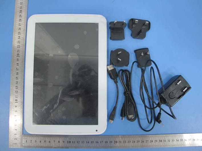
2AF2V-MGT101
Oct 25, 201510.1 inch Quad core capacitive touch tablet
Equipment Class
DTS - Digital Transmission System