2AF77-H1981653Blink XT2 Outdoor Camera
Immedia Semiconductor LLC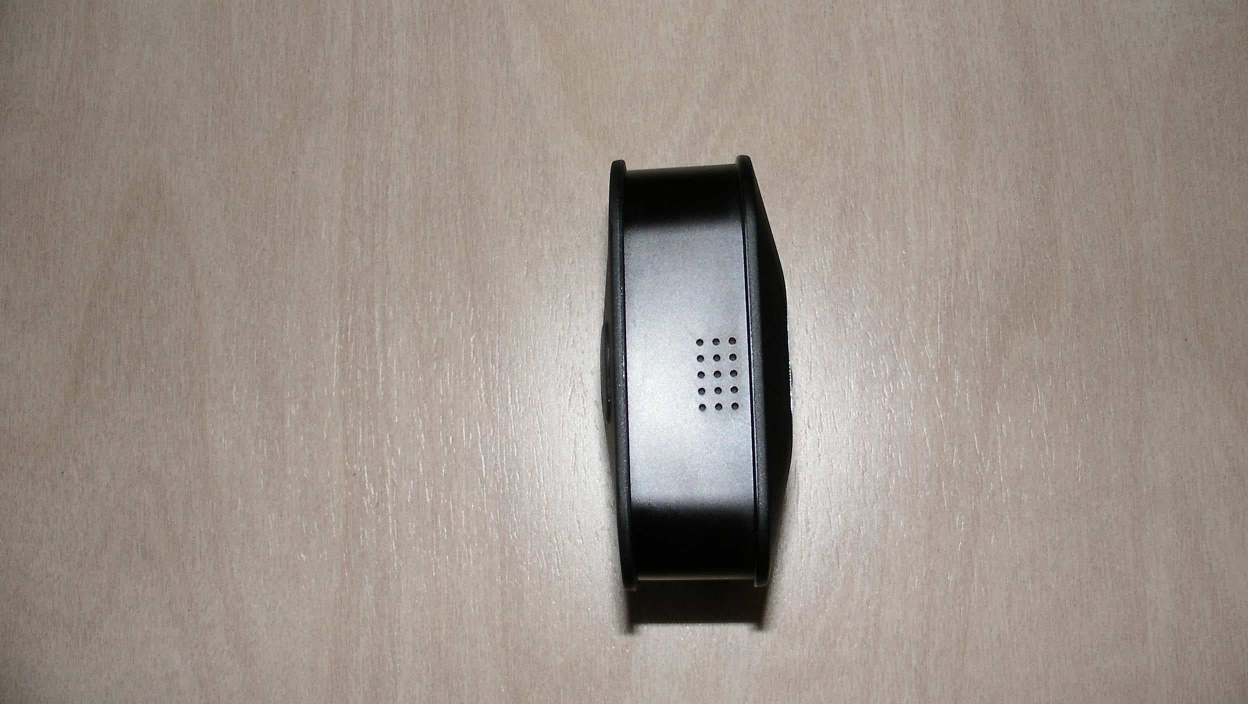
Click to zoom
Application Details
- Equipment Class
- DSS - Part 15 Spread Spectrum Transmitter
- Date of Grant
- Jan 13, 2020
- Application Purpose
- Original Equipment
- Date of Application
- Jan 13, 2020
- Equipment Note
- Blink XT2 Outdoor Camera
- Frequency Range
- 902.30000000 - 927.60000000
- Company
- Immedia Semiconductor LLC
- Country
- United States
Documents & Files
Document Text
Text extracted from the exhibit documents filed with the FCC. Open a document above to read the original.
Users Manual
Start Here Quick Start Guide Page 2Page 3 Thank you for purchasing the Blink XT2! You can install the Blink XT2 in three easy steps: To install your camera or system, you can: Download the Blink Home Monitor App (page 4) Connect your Sync Module (page 4) Add and position your camera(s) (page 6) Follow the in-app instructions as directed. Follow the steps listed in this guide. For more detailed instructions and/or how to customize your experience, scan the QR code or visit: support.blinkforhome.com Step 1: Step 2: Step 3: • • • If you’re adding a new system, go to Step 1 on page 4 for instructions on how to add your system. If you’re adding a camera to an existing system, go to Step 3 on page 6 for instructions on how to add your camera(s). Before you begin, please make sure you have the following minimum requirements: A mobile device running the minimum software requirement. You can check the latest software requirements by going to: blinkforhome.com/requirements Home WiFi Network (2.4GHz only). Internet access with upload speed of at least 2 Mbps. – – – How to get started: • • • Page 4Page 5 Download and launch the Blink Home Monitor App on your phone or tablet through the Apple App Store, Google Play Store, or Amazon App Store. Create a new Blink account. In your app, select “Add a System”. Follow the in-app instructions to complete Sync Module setup. Note: The Sync Module is required for your cameras to function. Blink Sync Module Step 1: Download the Blink Home Monitor App Step 2: Connect Your Sync Module A. B. A. B. Connectivity between the camera and the Sync Module is optimized when positioned within 100 ft of each other. * WiFi range is dependent on conditions. Distance between Blink devices and WiFi can vary. * Page 6Page 7 In your app, select “Add a Blink Device” and choose your camera. Remove the camera’s back cover by pressing the latch in the center downward and simultaneously pulling the cover away from the camera. Insert included 2 AA 1.5V non-rechargeable lithium metal batteries. Leave the back cover off and continue with in-app instructions to complete setup. Step 3: Add Your Camera(s) A. B. C. D. Place your camera in your desired location and go to camera settings to check that the WiFi and Sync Module signal strengths are strong. Start a live view in your Blink app and adjust your camera’s position as needed to make sure you’re seeing what you want. Note: Motion detection is optimized to detect when a subject moves across the field of view horizontally rather than directly toward or away from the camera. Positioning A. B. B BC 1.5V A A lithium batteries XT2 Camera Latch Push Best performance Camera view Page 8Page 9 Attach the mount (and if needed, optional extender) to the wall using the provided screws in your desired position. Snap the center hole on the back of the camera onto the circular portion of the mount. Once mounted, you can angle the camera to adjust your field of view. Your mounting kit includes: screws (2), a mount (1), and a mount extender * (1). * Note: The mount extender is optional. It helps increase the range of motion of the camera once it’s mounted. Mounting A. B. C. B A XT2 Back Mount Mount Extender (Optional) Mount Extender (Optional)MountScrews Page 10Page 11 If you are experiencing trouble or need help with your Blink XT2 or other Blink products, please contact our support team (available 24/7) through any of the following options: Your opinion matters and you can show others how Blink could help them by sharing your experience through any of the following options: To view support articles go to: support.blinkforhome.com Contact us by going to the hamburger menu ( ) in the app, tapping ‘Contact Customer Support’ and then pressing the blue ‘Call Tech Support’ button. To open a ticket online, visit: ‘support.blinkforhome.com’ and select ‘contact us’ in the top right corner of the page to submit a request form. Call us directly at: 781-332-5465 Having trouble?Enjoying your Blink XT2 system? • • • • Leave us a review from where you purchased. Share your experience with the Blink community at: community.blinkforhome.com Send us your best user videos via social (@blinkforhome) or email ([email protected])! We love seeing what our users catch on their Blink cameras. Page 12Page 13 Individual camera arm/disarm Individually arm or disarm cameras when your system is armed to detect motion by tapping the running man icon above each camera. The camera is armed when the icon is blue and disarmed when gray. Scheduled system arming To set your system to automatically arm or disarm, select “scheduling” in the system name dropdown menu of the app, then tap the plus sign to set dates and times via the clock. Live view recording Automatically record and save live views from your XT2 camera(s) by toggling on “Save all XT2 Live Views” in the system name dropdown menu at the top of the app home page. Blue recording light Remove the back cover of your camera(s) to manually switch the blue “REC. LED” to either “ON” (blue light will turn on when camera records or streams video) or “OFF” (light will not turn on to indicate when in use) by using tweezers or a similar tool. Make the most of your system Here are some additional features that come with your system: XT2 Back (no cover) On/off switch XT2 Back Cover Page 14Page 15 from the battery comes into contact with skin or clothes, flush with water immediately. Insert the batteries in the proper direction as indicated by positive (+) and negative (-) markings in battery compartment. It is highly recommended to use Lithium batteries with this product. Do not mix used and new batteries or batteries of different types (for example, Lithium and alkaline batteries). Always remove old, weak, or worn- out batteries promptly and recycle or dispose of them in accordance with Local and national disposal regulations. Other Safety and Maintenance Considerations Your Blink XT2 can withstand outdoor use and has been tested to wit…
Text truncated - open the document above for the full version.
Users Manual
Model: BCM00200U and BCM00201U Model Number: BCM00200U and BCM00201U Modèle du : BCM00200U et BCM00201U Numéro de modèle : BCM00200U et BCM00201U
External Photos
External Photographs Immedia Semiconductor, LLC. Blink Outdoor Wireless Camera Module, FCC ID: 2AF77-H1981653 IC 20741-H1981653 Front of Enclosure Left Side of Enclosure External Photographs Immedia Semiconductor, LLC. Blink Outdoor Wireless Camera Module, FCC ID: 2AF77-H1981653 IC 20741-H1981653 Rear of Enclosure Right Side of Enclosure External Photographs Immedia Semiconductor, LLC. Blink Outdoor Wireless Camera Module, FCC ID: 2AF77-H1981653 IC 20741-H1981653 Bottom of Enclosure Top of Enclosure
ID Label/Location Info
Immedia Semiconductor, LLC. Blink Outdoor Wireless Camera Module, FCC ID: 2AF77-H1981653 IC 20741-H1981653 ID Label Location Immedia Semiconductor, LLC. Blink Outdoor Wireless Camera Module, FCC ID: 2AF77-H1981653 IC 20741-H1981653 ID Label
Internal Photos
Internal Photographs Immedia Semiconductor, LLC. Blink Outdoor Wireless Camera Module, FCC ID: 2AF77-H1981653 IC 20741-H1981653 Back cover removed, Battery compartment Inside back cover removed Internal Photographs Immedia Semiconductor, LLC. Blink Outdoor Wireless Camera Module, FCC ID: 2AF77-H1981653 IC 20741-H1981653 Mezz Board Side 1 Mezz Board Side 2 Internal Photographs Immedia Semiconductor, LLC. Blink Outdoor Wireless Camera Module, FCC ID: 2AF77-H1981653 IC 20741-H1981653 Main Board with Camera PIR Board, Battery /Antenna Board Attached Main Board with Camera PIR Board Removed, Battery /Antenna Board Detached Internal Photographs Immedia Semiconductor, LLC. Blink Outdoor Wireless Camera Module, FCC ID: 2AF77-H1981653 IC 20741-H1981653 PIR Board Side1 PIR Board Side 2 Internal Photographs Immedia Semiconductor, LLC. Blink Outdoor Wireless Camera Module, FCC ID: 2AF77-H1981653 IC 20741-H1981653 Battery / Antenna Board Side 1 Battery / Antenna Board Side 2 Internal Photographs Immedia Semiconductor, LLC. Blink Outdoor Wireless Camera Module, FCC ID: 2AF77-H1981653 IC 20741-H1981653 Main board Side 1 Main Board Side 2
Test Report
FCC Part 15, Subpart C, Section 15.247 Test Report On Ou tdoor XT2 Blink Camera Module FCC ID: 2AF77-H1981653 Customer Name: Immedia Semiconductor, LLC Customer P.O: 2D-02586616 Date of Report: January 6, 2020 Test Report No: R-6458N-1 Test Start Date: October 25, 2019 Test Finish Date: November 8, 2019 Test Engineer: T. Hannemann Test Technician: M. Seamans Approved By: S. Wentworth Report Prepared By: P. Harris O ur letters, procedures and reports are for the exclusive use of the customer to whom they are addressed and their communication or the use of the name of Retlif Testing Laboratories must receive our prior written approval. Our letters, procedures and reports apply only to the sample tested and are not necessarily indicative of the qualities of apparently identical or similar products. The letters, procedures and reports and the name of Retlif Testing Laboratories or insignia are not to be used under any circumstances in advertising to the general public. This test report shall not be reproduced, except in full, without the written approval of Retlif Testing Laboratories. Report No. R-6458N-1 Page 2 of 59 Retlif Testing Laboratories R Technical Information Report Number: R-6458N-1 Customer: Immedia Semiconductor, LLC Address: 100 Riverpark Drive North Reading, MA 01864 Manufacturer: Immedia Semiconductor, LLC Manufacturer Address: 100 Riverpark Drive North Reading, MA 01864 Test Sample: Outdoor XT2 Blink Camera Module Model Number: BCM00201U Serial Number: 807-000-249 (Conducted Testing) 857-000-181 (Radiated Testing) FCC ID: 2AF77-H1981653 Type: Frequency Hopping Spread Spectrum Transmitter Power Requirements: 5 VDC via External 120 VAC power adapter or 3 VDC via internal batteries Frequency of Operation: 902.4 MHz to 927.6 MHz Equipment Class: DSS Antenna Type: Internal PCB Antenna – 1.5 dBi Gain Equipment Use: Used in a Home Monitoring System Test Specification: FCC Rules and Regulations Part 15, Subpart C, Section 15.247 Test Procedure: ANSI C63.4:2014 ANSI C63.10:2013 FCC 558074 D01 15.247 Meas Guidance v05r02, April 2, 2019 Test Facility: Retlif Testing Laboratories 101 New Boston Road Goffstown, NH 03045 FCC Designation Number: US5327 Report No. R-6458N-1 Page 3 of 59 Retlif Testing Laboratories R Tests Performed FCC Part 15, Subpart C Test Method 15.247(a)(1) Channel Separation 15.247(a)(1) 20 dB Bandwidth 15.247(a)(1)(i) Number of Channels and Occupancy Time 15.247(b)(2) and (4) Peak Conducted Output Power 15.247(d) Spurious Emissions, 30 MHz to 10 GHz 15.247(d) Field Strength of Spurious Emissions Section 15.207 (a) Conducted Emissions E UT Operation: The EUT is an outdoor Wi-Fi connected home security camera. The camera has a passive infrared motion sensor that can be used to trigger recording of video clips that are sent by Wi-Fi to internet based servers that relay the clips to the users’ mobile device. The EUT can also receive commands from the user to start transmission of video or update status. Table 1 – Support Equipment Description Manufacturer Model Number Serial Number Radiated Testing Long-Range USB Adapter ALFA Network AWUS036NHA 180636A0001785 Laptop PC HP Probook 450G5 5CD88466QTY Sync Module Immedia Semiconductor BSM00200U 270-090-633 Barcode Scanner Symbol DS6708-SR 2460000ION Camera Quiescent Current Tester Immedia Semiconductor SW Rev16 114 Conducted Testing Laptop PC HP Probook 450G5 5CD88466QTY Sync Module Immedia Semiconductor BSM002000 280-885-766 Report No. R-6458N-1 Page 4 of 59 Retlif Testing Laboratories R Certification and Signatures We certify that this report is a true representation of the results obtained from the tests of the equipment stated. We further certify that the measurements shown in this report were made in accordance with the procedures indicated and vouch for the qualifications of all Retlif Testing Laboratories personnel taking them. Scott Wentworth Branch Manager Todd Hannemann EMC Test Engineer iNARTE Certified Technician ATL-0255-T Non-Warranty Provision The testing services have been performed, findings obtained and reports prepared in accordance with generally accepted laboratory principles and practices. This warranty is in lieu of all others, either expressed or implied. No n-Endorsement This test report contains only findings and results arrived at after employing the specific test procedures and standards listed herein. It is not intended to constitute a recommendation, endorsement or certification of the product or material tested. This report must not be used by the client to claim product endorsement by ANSI National Accreditation Board (ANAB). Report No. R-6458N-1 Page 5 of 59 Retlif Testing Laboratories R Revision History Revisions to this document are listed below; the latest revised document supersedes all previous issues of this document: Revision Pages Affected - Date J anuary 6, 2020 Original Release Report No. R-6458N-1 Page 6 of 59 Retlif Testing Laboratories R Requirements and Test Results Requirement: FCC Section 15.247 (a)(1) Channel Separation and 20 dB Bandwidth Frequency hopping systems shall have hopping channel carrier frequencies separated by a minimum of 25 kHz or the 20 dB bandwidth of the hopping channel, whichever is greater. Alternatively, frequency hopping systems operating in the 2400-2483.5 MHz band may have hopping channel carrier frequencies that are separated by 25 kHz or two-thirds of the 20 dB bandwidth of the hopping channel, whichever is greater, provided the systems operate with an output power no greater than 125 mW. The system shall hop to channel frequencies that are selected at the system hopping rate from a pseudo randomly ordered list of hopping frequencies. Each frequency must be used equally on the average by each transmitter. The system receivers shall have input bandwidths that match the hopping channel bandwidths of their corresponding transmitters and shall shift frequencies in synchronization with the transmitted signals. • Results: The carrier frequencies were sep…
Text truncated - open the document above for the full version.
Test Setup Photos
Report No. R-6458N-1 Page 46 of 59 Retlif Testing Laboratories R Test Photographs Field Strength of Spurious Emissions Horizontal Antenna Polarization, 30 to 200 MHz Vertical Antenna Polarization, 30 to 200 MHz
Test Setup Photos
Report No. R-6458N-1 Page 47 of 59 Retlif Testing Laboratories R Test Photographs Field Strength of Spurious Emissions Horizontal Antenna Polarization, 200 MHz to 1 GHz Vertical Antenna Polarization, 200 MHz to 1 GHz Report No. R-6458N-1 Page 48 of 59 Retlif Testing Laboratories R Test Photographs Field Strength of Spurious Emissions Horizontal Antenna Polarization, 1 GHz to 10 GHz Vertical Antenna Polarization, 1 GHz to 10 GHz
Contact Information
Applicant
P. Douglas Grearson(HW Development Manager)
Technical Contact
Retlif Testing LaboratoriesTodd Hannemann
[email protected]6034974600
101 New Boston Road · Goffstown, New Hampshire · United States
Non-Technical Contact
Retlif Testing LaboratoriesTodd Hannemann
[email protected]6034974600
Test Firm
Retlif Testing LaboratoriesScott Wentworth
[email protected]603-497-4611
Technical Specifications
| # | Rule Parts | Frequency Range | Power Output |
|---|---|---|---|
| 1 | 15C | 902.3 MHz - 927.6 MHz | 17.10 mW |
Other Applications from Immedia Semiconductor LLC
2AF77-H2621890
May 26, 2026Communication Device
Equipment Class
DTS - Digital Transmission System2AF77-H2641971
Apr 16, 2026Wired Video Doorbell
Equipment Class
DTS - Digital Transmission System2AF77-H2641970
Apr 16, 2026Video Doorbell
Equipment Class
DTS - Digital Transmission System2AF77-H2511910
Sep 22, 2025Indoor/Outdoor powered camera
Equipment Class
DTS - Digital Transmission System
2AF77-H2211810
Jul 12, 2023Outdoor camera
Equipment Class
DSS - Part 15 Spread Spectrum Transmitter