2AF77-H2081653Blink XT2 Outdoor Camera
Immedia Semiconductor LLC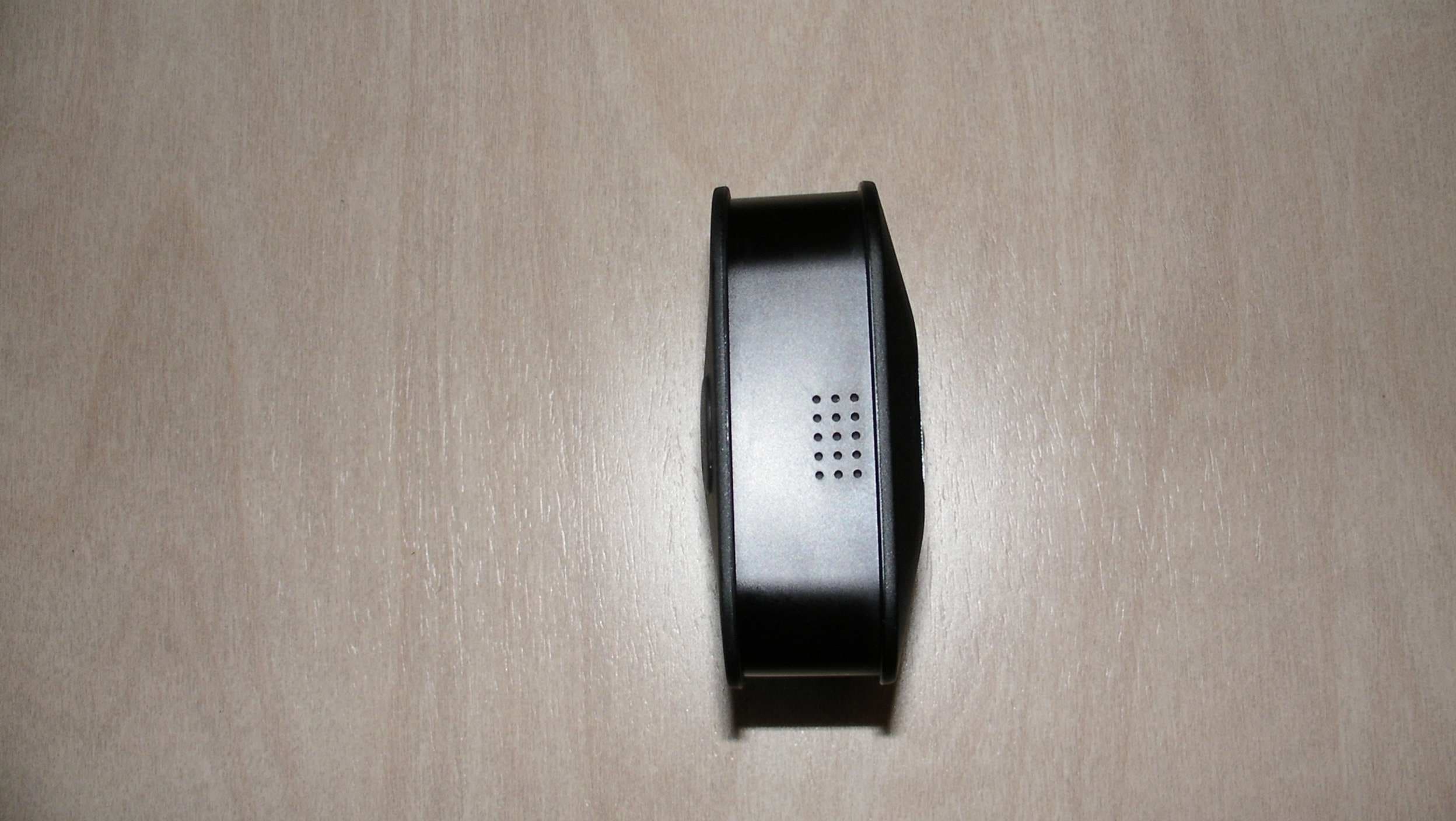
Click to zoom
Application Details
- Equipment Class
- DTS - Digital Transmission System
- Date of Grant
- Apr 02, 2020
- Application Purpose
- Original Equipment
- Date of Application
- Apr 02, 2020
- Equipment Note
- Blink XT2 Outdoor Camera
- Frequency Range
- 2412.00000000 - 2462.00000000
- Company
- Immedia Semiconductor LLC
- Country
- United States
Documents & Files
Document Text
Text extracted from the exhibit documents filed with the FCC. Open a document above to read the original.
External Photos
External Photographs Immedia Semiconductor, LLC. Blink Outdoor Wireless Camera Module, FCC ID: 2AF77-H2081653 IC 20741-H2081653 Front of Enclosure Left Side of Enclosure External Photographs Immedia Semiconductor, LLC. Blink Outdoor Wireless Camera Module, FCC ID: 2AF77-H2081653 IC 20741-H2081653 Rear of Enclosure Right Side of Enclosure External Photographs Immedia Semiconductor, LLC. Blink Outdoor Wireless Camera Module, FCC ID: 2AF77-H2081653 IC 20741-H2081653 Bottom of Enclosure Top of Enclosure
ID Label/Location Info
Immedia Semiconductor, LLC. Blink Outdoor Wireless Camera Module, FCC ID 2AF77-H2081653 IC 20741-H2081653 ID Label Location ID Label Location Immedia Semiconductor, LLC. Blink Outdoor Wireless Camera Module, FCC ID 2AF77-H2081653 IC 20741-H2081653 ID Label
Internal Photos
Internal Photographs Immedia Semiconductor, LLC. Blink Outdoor Wireless Camera Module, FCC ID: 2AF77-H2081653 IC 20741-H2081653 Back cover removed, Battery compartment Inside back cover removed ID Label Location ID Label Location Internal Photographs Immedia Semiconductor, LLC. Blink Outdoor Wireless Camera Module, FCC ID: 2AF77-H2081653 IC 20741-H2081653 Mezz Board Side 1 Mezz Board Side 2 Internal Photographs Immedia Semiconductor, LLC. Blink Outdoor Wireless Camera Module, FCC ID: 2AF77-H2081653 IC 20741-H2081653 Main Board with Camera PIR Board, Battery /Antenna Board Attached Main Board with Camera PIR Board Removed, Battery /Antenna Board Detached Internal Photographs Immedia Semiconductor, LLC. Blink Outdoor Wireless Camera Module, FCC ID: 2AF77-H2081653 IC 20741-H2081653 PIR Board Side1 PIR Board Side 2 Internal Photographs Immedia Semiconductor, LLC. Blink Outdoor Wireless Camera Module, FCC ID: 2AF77-H2081653 IC 20741-H2081653 Battery / Antenna Board Side 1 Battery / Antenna Board Side 2 Internal Photographs Immedia Semiconductor, LLC. Blink Outdoor Wireless Camera Module, FCC ID: 2AF77-H2081653 IC 20741-H2081653 Main board Side 1 Main Board Side 2
Test Report
FCC Part 15, Subpart C, Section 15.247 Test Report On Outdoor XT2 Blink Camera FCC ID: 2AF77-H2081653 Customer Name: Immedia Semiconductor, LLC Customer P.O: 2D-03171628 Date of Report: March 25, 2020 Test Report No: R-6502N-3 Test Start Date: March 6, 2020 Test Finish Date: March 12, 2020 Test Engineer: T. Hannemann Test Technician: M. Seamans Approved By: S. Wentworth Report Prepared By: P. Harris Our letters, procedures and reports are for the exclusive use of the customer to whom they are addressed and their communication or the use of the name of Retlif Testing Laboratories must receive our prior written approval. Our letters, procedures and reports apply only to the sample tested and are not necessarily indicative of the qualities of apparently identical or similar products. The letters, procedures and reports and the name of Retlif Testing Laboratories or insignia are not to be used under any circumstances in advertising to the general public. This test report shall not be reproduced, except in full, without the written approval of Retlif Testing Laboratories. Report No. R-6502N-3 Page 2 of 91 Retlif Testing Laboratories R Technical Information Report Number: R-6502N-3 Customer: Immedia Semiconductor, LLC Address: 100 Riverpark Drive North Reading, MA 01864 Manufacturer: Immedia Semiconductor, LLC Manufacturer Address: 100 Riverpark Drive North Reading, MA 01864 Test Sample: Outdoor XT2 Blink Camera Model Number: BCM00202U Serial Number: 887-000-575 (Conducted Testing) 807-000-302 (Radiated Testing) FCC ID: 2AF77-H2081653 Type: Digital Transmission - Direct Sequence Spread Spectrum Transmitter Power Requirements: 5 VDC via External 120 VAC power adapter or 3 VDC via internal batteries Frequency of Operation: 2412 MHz to 2462 MHz Equipment Class: DTS Antenna Type: Internal PCB Antenna – 2.0 dBi Gain Equipment Use: Used in a Home Monitoring System Test Specification: FCC Rules and Regulations Part 15, Subpart C, Section 15.247 Test Procedure: ANSI C63.4:2014 ANSI C63.10:2013 FCC 558074 D01 15.247 Meas Guidance v05r02, April 2, 2019 Test Facility: Retlif Testing Laboratories 101 New Boston Road Goffstown, NH 03045 FCC Designation Number: US5327 Report No. R-6502N-3 Page 3 of 91 Retlif Testing Laboratories R Tests Performed FCC Part 15, Subpart C Test Method 15.247(a)(2) Occupied Bandwidth (6dB Bandwidth) 15.247(b)(3) Power Output 15.247(d) Antenna Port, Conducted Emissions 15.247(e) Antenna Port, Power Density 15.247(d) Spurious Radiated Emissions, 30 MHz to 25 GHz 15.207(a) Conducted Emissions, Power Leads, 150 kHz to 30 MHz EUT Operation: The EUT is an outdoor Wi-Fi connected home security camera. The camera has a passive infrared motion sensor that can be used to trigger recording of video clips that are sent by Wi-Fi to internet based servers that relay the clips to the users mobile device. The EUT can also receive commands from the user to start transmissions of video on update status. Table 1 – Support Equipment Description Manufacturer Model Number Serial Number Radiated Testing and Conducted Emissions Bar Code Reader Symbol DS6706-SR 24600001ON Camera Quiescent Current Tester Immedia Semiconductor, LLC N/A N/A Long Range USB Adapter ALFA Network AwUS036NHA 180636A0001785 Blink Sync Module Immedia Semiconductor, LLC BSM00200V 270-090-633 Laptop PC HP Probook 450 G5 5CO8466QTY Conducted Testing Laptop PC HP Probook 450 G5 5CD8390C8N Report No. R-6502N-3 Page 4 of 91 Retlif Testing Laboratories R Certification and Signatures We certify that this report is a true representation of the results obtained from the tests of the equipment stated. We further certify that the measurements shown in this report were made in accordance with the procedures indicated and vouch for the qualifications of all Retlif Testing Laboratories personnel taking them. Scott Wentworth Branch Manager Todd Hannemann EMC Test Engineer iNARTE Certified Technician ATL-0255-T Non-Warranty Provision The testing services have been performed, findings obtained and reports prepared in accordance with generally accepted laboratory principles and practices. This warranty is in lieu of all others, either expressed or implied. Non-Endorsement This test report contains only findings and results arrived at after employing the specific test procedures and standards listed herein. It is not intended to constitute a recommendation, endorsement or certification of the product or material tested. This report must not be used by the client to claim product endorsement by ANSI National Accreditation Board (ANAB). Report No. R-6502N-3 Page 5 of 91 Retlif Testing Laboratories R Revision History Revisions to this document are listed below; the latest revised document supersedes all previous issues of this document: Revision Date Pages Affected - March 25, 2020 Original Release Report No. R-6502N-3 Page 6 of 91 Retlif Testing Laboratories R Requirements and Test Results Requirement: FCC Section 15.247(a)(2) Operation within the bands 902 - 928 MHz, 2400 - 2483.5 MHz and 5725 - 5850 MHz Systems using digital modulation techniques may operate in the 902 - 928 MHz, 2400 - 2483.5 MHz and 5725 - 5850 MHz bands. The minimum 6 dB bandwidths shall be at least 500 kHz. • Results: The minimum 6 dB bandwidth measured 9,268 kHz which complies with the requirement that the Bandwidth be no less than 500 kHz. Requirement: FCC Sections 15.247(b)(3) Operation within the bands 902 - 928 MHz, 2400 - 2483.5 MHz and 5725 - 5850 MHz The maximum peak conducted output power of the intentional radiator shall not exceed the following: For systems using digital modulation in the 902 - 928 MHz, 2400 - 2483.5 MHz and 5725 - 5850 MHz bands: 1 Watt. As an alternative to a peak power measurement, compliance with the one Watt limit can be based on a measurement of the maximum conducted output power. Maximum Conducted Output Power is defined as the total transmit power delivered to all antenna and antenna elements averaged across all symbols in the signaling alphab…
Text truncated - open the document above for the full version.
Test Setup Photos
Report No. R-6502N-3 Page 75 of 91 Retlif Testing Laboratories R Test Photographs Spurious Radiated Emissions, 30 MHz to 25 GHz EUT Configuration Report No. R-6502N-3 Page 76 of 91 Retlif Testing Laboratories R Test Photographs Spurious Radiated Emissions, 30 MHz to 25 GHz Horizontal Polarization, 30 to 200 MHz Vertical Polarization, 30 to 200 MHz Report No. R-6502N-3 Page 77 of 91 Retlif Testing Laboratories R Test Photographs Spurious Radiated Emissions, 30 MHz to 25 GHz Horizontal Polarization, 200 MHz to 1 GHz Vertical Polarization, 200 MHz to 1 GHz Report No. R-6502N-3 Page 78 of 91 Retlif Testing Laboratories R Test Photographs Spurious Radiated Emissions, 30 MHz to 25 GHz Horizontal Polarization, 1 to 18 GHz Vertical Polarization, 1 to 18 GHz Report No. R-6502N-3 Page 79 of 91 Retlif Testing Laboratories R Test Photographs Spurious Radiated Emissions, 30 MHz to 25 GHz Horizontal Polarization, 18 to 25 GHz Vertical Polarization, 18 to 25 GHz
Contact Information
Applicant
P. Douglas Grearson(HW Development Manager)
Technical Contact
Retlif Testing LaboratoriesTodd Hannemann
[email protected]6034974600
101 New Boston Rd · Goffstown, New Hampshire · United States
Non-Technical Contact
Retlif Testing LaboratoriesTodd Hannemann
[email protected]6034974600
Test Firm
Retlif Testing LaboratoriesScott Wentworth
[email protected]603-497-4611
Technical Specifications
| # | Rule Parts | Frequency Range | Power Output |
|---|---|---|---|
| 1 | 15C | 2.41 GHz - 2.46 GHz | 80.35 mW |
Other Applications from Immedia Semiconductor LLC
2AF77-H2621890
May 26, 2026Communication Device
Equipment Class
DTS - Digital Transmission System2AF77-H2641971
Apr 16, 2026Wired Video Doorbell
Equipment Class
DTS - Digital Transmission System2AF77-H2641970
Apr 16, 2026Video Doorbell
Equipment Class
DTS - Digital Transmission System2AF77-H2511910
Sep 22, 2025Indoor/Outdoor powered camera
Equipment Class
DTS - Digital Transmission System
2AF77-H2211810
Jul 12, 2023Outdoor camera
Equipment Class
DSS - Part 15 Spread Spectrum Transmitter