Text extracted from the exhibit documents filed with the FCC. Open a document above to read the original.
nuyu™ Sleep System 6 sheets, 8.5" x 11", color, double sided printing, folded and stapled. 22 inside pages + back and front cover, 24 printable sides total. Table of Contents: Section Page Number Welcome to nuyu™ 2 Important Information Set-up Instructions Fill the Water Tank Set up your Sleep System Connect your Sleep System How to Use your Sleep System Washing the Sleep Mat About the Sleep System Warranty 1. Front Cover a. HNY500 (bottom left hand corner) 2. Welcome a. Congratulations, you are the proud owner of a nuyu™ Sleep System! We can’t wait for you to experience better sleep. b. The Health o meter ® nuyu™ Sleep System regulates your body temperature to help you experience optimal sleep. c. www.healthometernuyu.com d. (Social Icons) 3. Important Information a. Keep at least 24 inches of cleared space around your Sleep System at all times to help prevent overheating. Do not place under your bed. b. FCC Warning: This device complies with Part 15 of the FCC Rules. Operation is subject to the following two conditions: (1) this device may not cause harmful interference, and (2) this device must accept any interference received, including interference that may cause undesired operation. Changes or modifications not expressly approved by the party responsible for compliance could void the user's authority to operate the equipment. NOTE: This equipment has been tested and found to comply with the limits for a Class B digital device, pursuant to Part 15 of the FCC Rules. These limits are designed to provide reasonable protection against harmful interference in a residential installation. This equipment generates, uses and can radiate radio frequency energy and, if not installed and used in accordance with the instructions, may cause harmful interference to radio communications. However, there is no guarantee that interference will not occur in a particular installation. If this equipment does cause harmful interference to radio or television reception, which can be determined by turning the equipment off and on, the user is encouraged to try to correct the interference by one or more of the following measures: -- Reorient or relocate the receiving antenna. -- Increase the separation between the equipment and receiver. -- Connect the equipment into an outlet on a circuit different from that to which the receiver is connected. -- Consult the dealer or an experienced radio/TV technician for help. To maintain compliance with FCC’s RF Exposure guidelines, This equipment should be installed and operated with minimum distance between 20cm the radiator your body: Use only the supplied antenna. c. 4. Set‐up Instructions a. Fill the Water Tank i. Find a space for your Sleep System next to your bed and set it on the floor. ii. Twist to the unlocked position and lift the green cap to open the water tank. iii. Using purified water only, fill the water tank until the MAX FILL line has been reached. Keep some extra water nearby, as you may need to fill the tank a second time after powering on the Sleep System. b. Set up your Sleep System i. Attach the sleep mat to the water tank. To do this, firmly push the connector of the grey hose onto the grey receiver of the water tank. You should feel it click, which confirms it is connected. If you do not feel it click, please press until it clicks. ii. After you’ve found a good space for your Sleep System, filled it with water, and have attached the sleep mat, plug it into a wall outlet. iii. Place the sleep mat under your fitted sheet, and over your mattress cover or mattress (if you do not use a mattress cover). iv. Place the sleep mat under where the torso section of your body typically lays on your bed. It is recommended that you place the top of the sleep mat just below where your pillow ends. This way, the sleep mat will be lying underneath your torso, from your shoulders to below your hips. Please adjust the sleep mat so that the connector tube is hanging off the bed. WARNING: Please ensure that the grey connector hose does not get pinched where it is set up. This will prevent water flow and may cause excess noise from the water tank. c. Connect your Sleep System i. Connect Your Sleep System ii. iii. PRESS and HOLD FOR 3 SECONDS the green button on the water tank to begin the pairing process. The “Connected” LED should now be flashing. iv. Connect your Sleep System, keeping your phone or tablet nearby, and follow the in‐app instructions. v. d. How to Use your Sleep System i. Once you have successfully paired your Sleep System with your nuyu™ app, you are ready to begin! ii. To control your Sleep System, open your nuyu™ app, and from the Home Page, tap the SLEEP section. (SHOW IMAGE OF HOME SCREEN, AND GREY OUT EVERYTHING EXCEPT FOR THE SLEEP SECTION) iii. In the upper right‐hand corner, tap the “zzz” icon. (SHOW ZZZ ICON) iv. v. You may set the Sleep System sleep duration two ways: 1. Set your wake up time (SHOW CLOCK ICON) 2. Set a Timer (SHOW TIMER ICON) 3. vi. Select a starting temperature vii. We’ve recommended a starting temperature for you in your nuyu™ app, but if you would like to change it based on personal preferences, try just one or two degrees to start with. Avoid setting your temperature at extreme lows or highs on the first night, as most people are comfortable between 72 – 74*F. viii. Please keep in mind that this is just the starting temperature, and your Sleep System will get slightly cooler in the middle of your sleep cycle to keep you comfortable, and will then warm back up to the starting temperature when it’s time to wake up. ix. To begin running the Sleep System, press START (SHOW START SCREEN AND HIGHLIGHT START AREA) x. The Sleep System is now running (SHOW SLEEP RUNNING SCREEN) and will do so until it has reached the wake up time or the end of the timer. To manually turn off the Sleep System, swipe up on “WAKE UP” in your app, or press the green “zzz” button (SHOW ZZZ BUTTON). e. Washing the Sleep Mat i. If you would like to wash…
Text truncated - open the document above for the full version.
SCS-F18: Project and Product Certification Representative Authorization Letter Page 1 of 2 Rev 5.0 775 Montague Expressway Milpitas, CA 95035 Tel: 408-526-1188 Fax: 408-526-1088 Email: [email protected] Project and Product Certification Representative Authorization Letter Reason for Amendment (current / obsolete) Revision History Approved Date From To Initial Release (obsolete) 1.0 1.0 Nov-14-2006 Revised wording (obsolete) 1.0 2.0 Sept–25-2007 Updated company template (obsolete) 2.0 3.0 Jan-31-2012 Updated letter information (obsolete) 3.0 4.0 May-23-2014 Added FCC ID field (current) 4.0 5.0 Sept 16 2014 SCS-F18: Project and Product Certification Representative Authorization Letter Page 2 of 2 Rev 5.0 Eagle Electric (Shenzhen) Co., LTD 2015-07-31 To: SIEMIC, INC. 775 Montague Expressway, Milpitas, CA 95035 USA Dear Sir/Madam, Re: Product Certification Representative Authorization Letter We,Eagle Electric (Shenzhen) Co., LTD hereby authorize SIEMIC, Inc. to act as a Certification Body for certifying for the following project(s): Sleep System Model Number: HNY500 FCC ID: 2AFCUHNY500 Sincerely, Rongjie Wen /Engineering manager E-mail: [email protected] Phone: 0755-27642811-228 Fax: 0755-27642931 Address NO.4, Industry Area, Shiyan Town Baoan District Shenzhen China
SCS-F19: Confidentiality Request Letter Page 1 of 2 Rev 4.0 775 Montague Expressway Milpitas, CA 95035 Tel: 408-526-1188 Fax: 408-526-1088 Email: [email protected] Confidentiality Request Letter Reason for Amendment (current / obsolete) Revision History Approved Date From To Initial Release (obsolete) 1.0 1.0 Nov-14-2006 Adding CFR 2.459 (obsolete) 1.0 2.0 August – 11 - 2008 Updated company template & Added text box (obsolete) 2.0 3.0 Jan-31-2012 Added IC confidentiality letter form (current) 3.0 4.0 March-26-2015 SCS-F19: Confidentiality Request Letter Page 2 of 2 Rev 4.0 Eagle Electric (Shenzhen) Co., LTD 2015-07-31 To: Federal Communications Commission Authorization and Evaluation Division 7435 Oakland Mills Road Columbia, MD Subject: Permanent Confidentiality Request for FCC ID: 2AFCUHNY500 We hereby request confidential treatment of information accompanying this application as outlined below: - Block Diagram - Schematics - Operational Description The above materials contain trade secrets and proprietary information not customarily released to the public. The public disclosure of these materials may be harmful to the applicant and provide unjustified benefits to its competitors. The applicant understands that pursuant to Section 0.457 & 0.459 of the Rules, disclosure of this application and all accompanying documentation will not be made before the date of the Grant for this application. Sincerely, Signature Rongjie Wen /Engineering manager E-mail: [email protected] Phone: 0755-27642811-228 Fax: 0755-27642931 Address NO.4, Industry Area, Shiyan Town Baoan District Shenzhen China
Sleep System MODEL No.: HNY500 FCC ID: 2AFCUHNY500 This device complies with Part 15 of the FCC Rules. Operation is subject to the following two conditions: (1) this device may not cause harmful interference, and (2) this device must accept any interference received, including interference that may cause undesired operation.
Label Location Proposed Label Location on EUT
Module Antenna
FCC ID: 2AFCUHNY500 RF EXPOSURE EVALUATION According to FCC 1.1310: The criteria listed in the following table shall be used to evaluate the environment impact of human exposure to radio frequency(RF) Radiation as specified in §1.1307(b) Limits for Maximum Permissible Exposure (MPE) Frequency Range(MHz) Electric Field Strength(V/m) Magnetic Field Strength(A/m) Power Density(mW/cm 2 ) Average Time (A) Limits for Occupational/Control Exposures 300-1500 -- -- F/300 6 1500-100000 -- -- 5 6 (B) Limits for General Population/Uncontrol Exposures 300-1500 -- -- F/1500 6 1500-100000 -- -- 1 30 11.1 Friis transmission formula: Pd= (Pout*G)\ (4*pi*R 2 ) Where Pd= Power density in mW/cm 2 Pout=output power to antenna in mW G= Numeric gain of the antenna relative to isotropic antenna Pi=3.1416 R= distance between observation point and center of the radiator in cm Pd the limit of MPE,1mW/cm 2 . If we know the maximum gain of the antenna and total power input to the antenna, through the calculation, we will know the distance where the MPE limit is reached. mW = 10^( dBm/10) 11.2 Measurement Result Operation Frequency: 2402MHz-2480MHz; Power density limited: 1mW/ cm 2; Antenna gain: PCB Antenna 1dBi; Channel Freq. (MHz) modulation conducted power (mW) conducted power (dBm) Tune-up power (dBm) Max tune-up power (dBm) Antenna Gain Numeric Evaluation result (mW/cm2) Power density Limits (mW/cm2 ) 2402 GFSK 0.54 -2.65 -3.5±1 -2.5 1.26 0.000141 1 2440 0.44 -3.55 -3.5±1 -2.5 1.26 0.000141 1 2480 0.38 -4.20 -3.5±1 -2.5 1.26 0.000141 1
TRF No.: FCC 15.247 Page 1 of 43 Report No.: ES150630444E Ver.1.0 Access to the World FCC 47 CFR PART 15 SUBPART C CERTIFICATION TEST REPORT For Sleep System MODEL No.: HNY500 FCC ID: 2AFCUHNY500 Trademark: nuyu™ REPORT NO.: ES150630444E ISSUE DATE: July 31, 2015 Prepared for Eagle Electric (Shenzhen) Co., LTD NO.4, Industry Area, Shiyan Town, Baoan District, Shenzhen, China Prepared by SHENZHEN EMTEK CO., LTD. Bldg 69, Majialong Industry Zone, Nanshan District, Shenzhen, Guangdong, China TEL: 86-755-26954280 FAX: 86-755-26954282 TRF No.: FCC 15.247 Page 2 of 43 Report No.: ES150630444E Ver.1.0 Access to the World Table of Contents 1 TEST RESULT CERTIFICATION ...................................................................................................................... 3 2 EUT TECHNICAL DESCRIPTION .................................................................................................................... 4 3 SUMMARY OF TEST RESULT ........................................................................................................................... 6 4 TEST METHODOLOGY ...................................................................................................................................... 7 4.1 GENERAL DESCRIPTION OF APPLIED STANDARDS .......................................................................... 7 4.2 MEASUREMENT EQUIPMENT USED ..................................................................................................... 7 4.3 DESCRIPTION OF TEST MODES ............................................................................................................. 8 5 FACILITIES AND ACCREDITATIONS ............................................................................................................. 9 5.1 FACILITIES ................................................................................................................................................. 9 5.2 LABORATORY ACCREDITATIONS AND LISTINGS .............................................................................. 9 6 TEST SYSTEM UNCERTAINTY ...................................................................................................................... 10 7 SETUP OF EQUIPMENT UNDER TEST ......................................................................................................... 11 7.1 RADIO FREQUENCY TEST SETUP 1 ..................................................................................................... 11 7.2 RADIO FREQUENCY TEST SETUP 2 ..................................................................................................... 11 7.3 CONDUCTED EMISSION TEST SETUP ................................................................................................. 12 7.4 SUPPORT EQUIPMENT ........................................................................................................................... 12 8 TEST REQUIREMENTS .................................................................................................................................... 13 8.1 DTS (6DB) BANDWIDTH ........................................................................................................................ 13 8.2 MAXIMUM PEAK CONDUCTED OUTPUT POWER ............................................................................ 16 8.3 MAXIMUM POWER SPECTRAL DENSITY .......................................................................................... 19 8.4 UNWANTED EMISSIONS IN NON-RESTRICTED FREQUENCY BANDS ......................................... 22 8.5 RADIATED SPURIOUS EMISSION ......................................................................................................... 27 8.6 CONDUCTED EMISSIONS TEST ........................................................................................................... 40 8.7 ANTENNA APPLICATION ....................................................................................................................... 43 TRF No.: FCC 15.247 Page 3 of 43 Report No.: ES150630444E Ver.1.0 Access to the World 1 TEST RESULT CERTIFICATION Applicant: Eagle Electric (Shenzhen) Co., LTD Manufacturer: Eagle Electric (Shenzhen) Co., LTD EUT Description: Sleep System Model Number: HNY500 File Number: ES150630444E Date of Test: June 30, 2015 to July 31, 2015 Measurement Procedure Used: APPLICABLE STANDARDS STANDARD TEST RESULT FCC 47 CFR Part 2, Subpart J:2014 FCC 47 CFR Part 15, Subpart C:2014 PASS The above equipment was tested by SHENZHEN EMTEK CO., LTD. The test data, data evaluation, test procedures, and equipment configurations shown in this report were made in accordance with the procedures given in ANSI C63.10 (2013) and the energy emitted by the sample EUT tested as described in this report is in compliance with the requirements of FCC Rules Part 2 and Part 15.247 The test results of this report relate only to the tested sample identified in this report Date of Test : June 30, 2015 to July 31, 2015 Prepared by : Jack Li/Editor Reviewer : Joe Xia/Supervisor Approve & Authorized Signer : Lisa Wang/Manager TRF No.: FCC 15.247 Page 4 of 43 Report No.: ES150630444E Ver.1.0 Access to the World 2 EUT TECHNICAL DESCRIPTION Characteristics Description Device Type: Fixed device Data Rate: 1Mbps Modulation: GFSK Bluetooth Version: Bluetooth 4.0 for BLE Operating Frequency Range(s): 2402MHz ~ 2480MHz; Number of Channels: 40 Channels Transmit Power Max: -2.65dBm Antenna Type: PCB antenna Antenna Gain: 1dBi ; Power supply: AC supply: AC 120V /60Hz Adapter supply: Note: for more details, please refer to the User’s manual of the EUT. TRF No.: FCC 15.247 Page 5 of 43 Report No.: ES150630444E Ver.1.0 Access to the World Modified Information Version. Summary Date of Rev. Report No. Ver.1.0 Original Report 2015-07-31 ES150630444E TRF No.: FCC 15.247 Page 6 of 43 Report No.: ES150630444E Ver.1.0 Access to the World 3 SUMMARY OF TEST RESULT FCC Part Clause Test Parameter Verdict Remark 15.247(a)(2) DTS (…
Text truncated - open the document above for the full version.
Conducted Measurement Photo Radiated Emission Test
| # | Rule Parts | Frequency Range | Power Output |
|---|---|---|---|
| 1 | 15C | 2.40 GHz - 2.48 GHz | 500.00 µW |

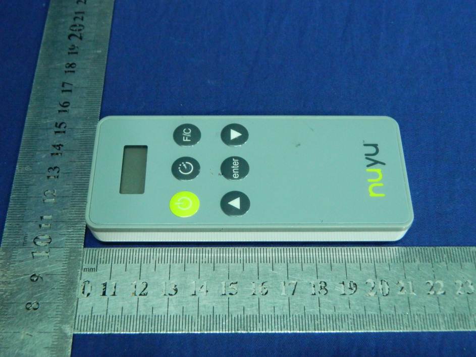
Bluetooth Remote Control
Equipment Class
DTS - Digital Transmission System