2AFOIHUBHub
Triple Plus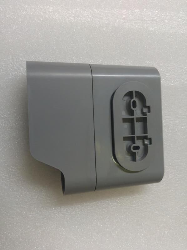
Click to zoom
Application Details
- Equipment Class
- DSC - Part 15 Security/Remote Control Transmitter
- Date of Grant
- Mar 04, 2020
- Application Purpose
- Original Equipment
- Date of Application
- Mar 03, 2020
- Equipment Note
- Hub
- Frequency Range
- 915.00000000 - 915.00000000
- Company
- Triple Plus
- Country
- Israel
Documents & Files
Document Text
Text extracted from the exhibit documents filed with the FCC. Open a document above to read the original.
Users Manual
Tripleplus Ltd. | 5 Hamada St., High Tech Park, Yoqneam, 2069200, Israel | +972-(0)72-2211370 | [email protected] | www.tripleplus.io Triple+ CLM ™ HUB V2.0 Installer Guide v3.0 P/N: CLM-COAMAP-2-00, CLM-COEMEA-2-00 Welcome Thank you for choosing Triple+ CLM™. Triple+ CLM™ is the ultimate IoT cloud-based system for home safety. The system is managed via an App and is designed to prevent damage due to water leakage. Triple+ offers you a total peace of mind at home or away. Please note Please read these instructions carefully and follow the system's installation and commissioning steps. Maintain this document in a safe place for future reference. Contact your authorized installer with any questions. Warning! This product was designed to prevent water leakage damages and should be used for this purpose only. Triple+ CLM™ system Triple+ CLM™ line of products includes innovative battery-operated devices which enables the automated control of water valves. This is unified under the “Smart Home” umbrella. The Triple+ CLM™ HUB serves as a Gateway that ensures a secured communication between the system devices, Triple+ cloud and App. Triple+ CLM™ integrates easily into the Smart Home IoT ecosystem, providing a unique cloud-based secured platform for Water Leak Management. Triple+ CLM™ HUB V2.0 technical specification: Part No. CLM-COAMAP-2-00, CLM-COEMEA-2-00 Product description Communicates with the connected devices (RF) and the Triple+ cloud (Wi-Fi) Dimensions 105x35x110mm (4.13x1.37 x4.33”) Weight 146gr (5.15 Oz) Power supply External Adaptor Input 110-240 V AC Operation voltage 5V (2 x AA backup batteries. Up to 8 hours) Operating RF 868/915 MHz Transmission range Open space - up to 230 m (750 ft.) In enclosed space - up to 120 m (390 ft.) Avoid installing in a metal cabinet. Working Temperature -20 to +50 0 C (-4 to +122 0 F) Certifications FCC ID: 2AFOIHUB IC: 20798-HUB HUB description A. Power outlet B. Lower cover C. Wall mounting bracket (rear part) D. Power LED E. RGB LED indicator Batteries Installation 1. Slide down the lower cover 2. Insert 2XAA batteries (included) 3. Slide back up the lower cover HUB Wall installation 1. Attach the wall mounting bracket to its location and mark the holes for the mounting screws 2. Place the HUB’s rear mounting pins close to the wall and gently slide down the wall mount dimples Warning! Do not attempt to rotate the HUB on the mounting to avoid physical damage to the enclosure. HUB Installation Regular mode Download and install the Triple+ APP from the Play Store/ Appstore Verify that your mobile phone is connected to the desired Wi-Fi network (the HUB will connect to this network) Login to the APP and create a Username and password Follow the installation steps in the application (your phone must be connected to the Wi-Fi network) Wait for the installation to finish and place the system devices (flood detectors, Flow sensors, actuators) in the desired locations verify that all the devices communicate with the Triple+ CLM™ HUB V2.0 by verifying the “OK” in the App main screen and all devices icons appear with ‘green’ color Technician mode – only applicable if the above method did not finish successfully In the connection screen in the user app tap “Technician Mode” Follow the installation steps in the application Go to the Wi-Fi network selection screen on your mobile phone and connect to the Triple+ Wi-Fi network - no password is required After the HUB connected to the Wi-Fi - the installation will start automatically Wait for the installation to finish and place the system devices (flood detectors, Flow sensors, actuators) in the desired locations verify that all the devices communicate with the Triple+ CLM™ HUB V2.0 by verifying the “OK” in the App main screen and all devices icons appear with ‘green’ color RGB LED behavior GREEN flashes every 2 Sec – OK BLUE flashes every 2 Sec – Failure in communication with the Triple+ Cloud or with any system's device RED flashes every 2 Sec – battery status warning / low battery, in Hub or one of the devices. System Component synchronization and activation Triple+ CLM™ devices are installed and activated using the Triple+ CLM™ installer’s or End-User APP available on AppStore and Google Play. This Hub is designed for indoor use only and should be installed by an authorized installer and operates on Wi-Fi communication. Warranty instructions Please visit www.tripleplus.io/support for warranty, technical support, terms and conditions or troubleshooting. PW000 1 20 1 2 Tripleplus Ltd. | 5 Hamada St., High Tech Park, Yoqneam, 2069200, Israel | +972-(0)72-2211370 | [email protected] | www.tripleplus.io FCC STATEMENTS This device complies with Part 15 of the FCC Rules. Operation is subject to the following two conditions: (1) This device may not cause harmful interference, and (2) This device must accept any interference received, including interference that may cause undesired operation. Changes or modifications not expressly approved by the party responsible for compliance could void the user’s authority to operate this equipment. Note: This equipment has been tested and found to comply with the limits for a Class B digital device, pursuant to part 15 of the FCC Rules. These limits are designed to provide reasonable protection against harmful interference in a residential installation. This equipment generates, uses and can radiate radio frequency energy and, if not installed and used in accordance with the instructions, may cause harmful interference to radio communications. However, there is no guarantee that interference will not occur in a particular installation. If this equipment does cause harmful interference to radio or television reception, which can be determined by turning the equipment off and on, the user is encouraged to try to correct the interference by one or more of the following measures: — Reorient or relocate the receiving antenna. — Incre…
Text truncated - open the document above for the full version.
External Photos
Triple Plus Ltd. FCC ID: 2AFOIHUB IC: 20798-HUB Page 1 of 3 EXTERNAL PHOTOGRAPHS This document contains 2 photographs Triple Plus Ltd. FCC ID: 2AFOIHUB IC: 20798-HUB Page 2 of 3 Photograph No.1 HUB unit front view Triple Plus Ltd. FCC ID: 2AFOIHUB IC: 20798-HUB Page 3 of 3 Photograph No.2 HUB unit bottom view
ID Label/Location Info
Triple Plus Ltd. FCC ID:2AFOIHUB IC:20798-HUB Page 1 of 2 Label Model number CLM-COAMAP-2-00 Triple Plus Ltd. FCC ID:2AFOIHUB IC:20798-HUB Page 2 of 2 Label location Label with FCC ID:2AFOIHUB and IC:20798-HUB will be located at the bottom part of the unit’s shell. The statement according to FCC part 15 §15.19(a)(3).
Internal Photos
Triple Plus Ltd. FCC ID: 2AFOIHUB IC: 20798-HUB Page 1 of 5 INTERNAL PHOTOGRAPHS This document contains 4 photographs Triple Plus Ltd. FCC ID: 2AFOIHUB IC: 20798-HUB Page 2 of 5 Photograph No.1 HUB unit internal view Triple Plus Ltd. FCC ID: 2AFOIHUB IC: 20798-HUB Page 3 of 5 Photograph No.2 HUB unit PCB front view Triple Plus Ltd. FCC ID: 2AFOIHUB IC: 20798-HUB Page 4 of 5 Photograph No.3 Print side of the main PCB Triple Plus Ltd. FCC ID: 2AFOIHUB IC: 20798-HUB Page 5 of 5 Photograph No.4 HUB unit antenna
Operational Description
Triple+ Hub Product/technical description The Hub communicate with Triple+ wireless flood detectors and Triple+ actuators and update the cloud on the status of connected devices. The hub may automatically close the actuator on flood detection based on the hub configuration. Antenna description: 1. Antenna type: Helical 2. Gain: 2dBi 3. Triple+ production 4. Operational frequency: single channel 915MHz Power operation range: 1. From 0dBm to 10dBm Hopping Transceiver: Not Applicable
Test Report
Hermon Laboratories Ltd. P.O. Box 23, Binyamina 3055001, Israel Tel. +972 4628 8001 Fax. +972 4628 8277 E-mail: [email protected] Page 1 of 37 Report ID: TRIRAD_FCC.34184.Hub_Rev2 Date of Issue: 24-Feb-20 ELECTRICAL TESTING 0839.01 TEST REPORT ACCORDING TO: FCC CFR 47 Part 15 subpart C, section 15.231 RSS-210 issue 9 Annex A FOR: Triple Plus Ltd. CLM HUB V2 915 MHz Model: CLM-COAMAP-2-00 FCC ID: 2AFOIHUB IC: 20798-HUB This report is in conformity with ISO/ IEC 17025. The "A2LA Accredited" symbol endorsement applies only to the tests and calibrations that are listed in the scope of Hermon Laboratories accreditation. The test results relate only to the items tested. This test report shall not be reproduced in any form except in full with the written approval of Hermon Laboratories Ltd. Report ID: TRIRAD_FCC.34184.Hub_Rev2Hub Date of Issue: 24-Feb-20 Page 2 of 37 Table of contents 1 Applicant information ..................................................................................................................................................... 3 2 Equipment under test attributes .................................................................................................................................... 3 3 Manufacturer information .............................................................................................................................................. 3 4 Test details .................................................................................................................................................................... 3 5 Tests summary .............................................................................................................................................................. 4 6 EUT description ............................................................................................................................................................. 5 6.1 General information ....................................................................................................................................................... 5 6.2 Test configuration .......................................................................................................................................................... 5 6.3 Changes made in EUT .................................................................................................................................................. 5 6.4 Transmitter characteristics ............................................................................................................................................ 6 7 Transmitter tests according to 47CFR part 15 subpart C requirements ........................................................................ 7 7.1 Periodic operation requirements ................................................................................................................................... 7 7.2 Field strength of emissions .......................................................................................................................................... 11 7.3 Occupied bandwidth test ............................................................................................................................................. 21 7.4 Conducted emissions .................................................................................................................................................. 23 7.5 Antenna requirements ................................................................................................................................................. 26 8 APPENDIX A Test equipment and ancillaries used for tests ....................................................................................... 27 9 APPENDIX B Test equipment correction factors ......................................................................................................... 28 10 APPENDIX C Test laboratory description ................................................................................................................... 34 11 APPENDIX D Measurement uncertainties .................................................................................................................. 35 12 APPENDIX E Specification references........................................................................................................................ 36 13 APPENDIX F Abbreviations and acronyms ................................................................................................................. 37 Report ID: TRIRAD_FCC.34184.Hub_Rev2Hub Date of Issue: 24-Feb-20 Page 3 of 37 1 Applicant information Client name: Triple Plus Ltd. Address: 5 Hamada street, Yokneam 2069200, Israel Telephone: +972-72-22-11-370 Fax: +972-4-959-3991 E-mail: [email protected] Contact name: Mr. Yuval Abraham 2 Equipment under test attributes Product name: CLM Hub V2 915 MHz Product type: Hub Model(s): CLM-COAMAP-2-00 Serial number: Prototype Hardware version: 2.1 Software release: 3.0.5.0 Receipt date 15-Sep-19 3 Manufacturer information Manufacturer name: Triple Plus Ltd. Address: 5 Hamada street, Yokneam 2069200, Israel Telephone: +972-72-22-11-370 Fax: +972-4-959-3991 E-Mail: [email protected] Contact name: Mr. Yuval Abraham 4 Test details Project ID: 34184 Location: Hermon Laboratories Ltd. P.O. Box 23, Binyamina 3055001, Israel Test started: 06-Oct-19 Test completed: 15-Oct-19 Test specification(s): FCC 47CFR part 15, subpart C, §15.231; RSS-210 issue 9 Annex A Report ID: TRIRAD_FCC.34184.Hub_Rev2Hub Date of Issue: 24-Feb-20 Page 4 of 37 5 Tests summary Test Status Transmitter characteristics FCC Part 15, Section 231(a) / RSS-210, Section A1.1, Periodic operation requirements Pass FCC Part 15, Section 231(a) / RSS-210, Section A1.2, Field strength of emissions Pass FCC Part 15, Section 231(c) / RSS-210, Section A1.3, Occupied bandwidth Pass FCC Part 15, Section 207…
Text truncated - open the document above for the full version.
Test Setup Photos
Triple Plus Ltd. FCC ID:2AFOIHUB IC:20798-HUB Page 1 of 4 SETUP PHOTOGRAPHS This document contains 3 photographs Triple Plus Ltd. FCC ID:2AFOIHUB IC:20798-HUB Page 2 of 4 Photograph No.1 Setup for spurious emission field strength measurements in the anechoic chamber below 30 MHz Triple Plus Ltd. FCC ID:2AFOIHUB IC:20798-HUB Page 3 of 4 Photograph No.2 Setup for carrier field strength measurements in the anechoic chamber in 30 – 1000 MHz range Triple Plus Ltd. FCC ID:2AFOIHUB IC:20798-HUB Page 4 of 4 Photograph No.3 Setup for spurious emission field strength measurements in the anechoic chamber above 1000 MHz range
Contact Information
Applicant
Michael Isakov(CEO)
Technical Contact
Hermon Laboratories Ltd.Michael Nikishin
[email protected]972 4626 8440
Harakevet Industrial zone, P.O.Box 23 · Israel
Non-Technical Contact
Triple PlusYuval Abraham
[email protected]972-72-2211370
Test Firm
Hermon Laboratories Ltd.George Shleimovich
Technical Specifications
| # | Rule Parts | Frequency Range | Power Output |
|---|---|---|---|
| 1 | 15.231 | 915 MHz - 915 MHz | - |
Other Applications from Triple Plus
2AFOICBMUSLR5
Jul 03, 2024Flood family
Equipment Class
DSS - Part 15 Spread Spectrum Transmitter
2AFOICBMSHLR5
Jul 03, 2024Shut Off Actuator
Equipment Class
DSS - Part 15 Spread Spectrum Transmitter
2AFOICBMCOLR5
Jul 03, 2024Controller
Equipment Class
DSS - Part 15 Spread Spectrum Transmitter
2AFOILORA
Jun 01, 2020LoRa based Ball valve Actuator security system
Equipment Class
DTS - Digital Transmission System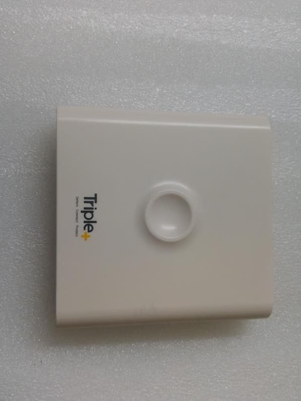
2AFOICIC
Apr 10, 2020Irrigation Controller
Equipment Class
DSC - Part 15 Security/Remote Control Transmitter