2AFOILORALoRa based Ball valve Actuator security system
Triple Plus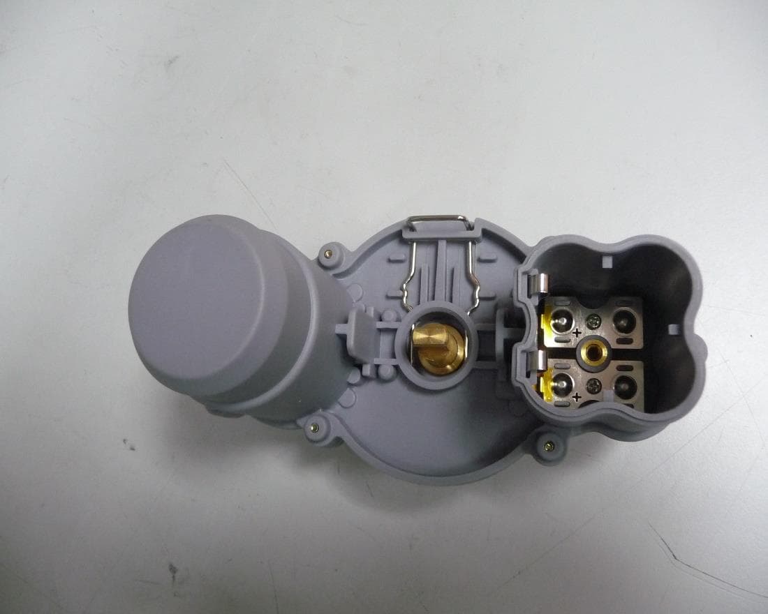
Click to zoom
Application Details
- Equipment Class
- DTS - Digital Transmission System
- Date of Grant
- Jun 01, 2020
- Application Purpose
- Original Equipment
- Date of Application
- May 27, 2020
- Equipment Note
- LoRa based Ball valve Actuator security system
- Frequency Range
- 902.40000000 - 927.60000000
- Company
- Triple Plus
- Country
- Israel
Documents & Files
Document Text
Text extracted from the exhibit documents filed with the FCC. Open a document above to read the original.
Users Manual
SHUTTIE Installation Manual Part No.HDW-000081-001 Product descriptionThe wireless, battery operated water Actuator is mounted on an ISO5211 ball valve installed on the main water line. The water supply automatically shuts off whenever a leak is detected. Shutoff can also be manually controlled by the user. Dimensions 142x73x92mm (5.6x2.87x3.62’’) Weight 640g (22.5 oz) Power supply4 x 3V batteries (CR123A) Operation voltage6V Battery life spanUp to four years based on one operation per day/5 days a week. Operating RF915 MHz Transmission rangeOpen space - up to 230 m (750 ft.) In enclosed space - up to 120 m (390 ft.) Avoid installing in a metal cabinet. Certification FCC: 2AFOILORA IC: 20798-LORA IP Rating IEC60529IP67 Working temperature-20C to +50C (-40F to +1220F) SHUTTIE SPECIFICATION Warning! This product includes moving parts. Keep your fingers or any other objects away. Warning! This product was designed to prevent water leakage damages and should be used for this purpose only. FCC STATEMENTS This device complies with Part 15 of the FCC Rules. Operation is subject to the following two conditions: (1) This device may not cause harmful interference, and (2) This device must accept any interference received, including interference that may cause undesired operation. Changes or modifications not expressly approved by the party responsible for compliance could void the user’s authority to operate this equipment. Note: This equipment has been tested and found to comply with the limits for a Class B digital device, pursuant to part 15 of the FCC Rules. These limits are designed to provide reasonable protection against harmful interference in a residential installation. This equipment generates, uses and can radiate radio frequency energy and, if not installed and used in accordance with the instructions, may cause harmful interference to radio communications. However, there is no guarantee that interference will not occur in a particular installation. If this equipment does cause harmful interference to radio or television reception, which can be determined by turning the equipment off and on, the user is encouraged to try to correct the interference by one or more of the following measures: — Reorient or relocate the receiving antenna. — Increase the separation between the equipment and receiver. — Connect the equipment into an outlet on a circuit different from that to which the receiver is connected. — Consult the dealer or an experienced radio/TV technician for help. WARNING – RF EXPOSURE COMPLIANCE: This equipment should be installed and operated with a minimum distance 20cm between the radiator and your body. This Class B digital apparatus complies with Canadian ICES-003. Cet appareil numerique de la classe B est conforme a la norme NMB-003 du Canada. IC STATEMENTS This device contains licence-exempt transmitter(s)/receiver(s) that comply with Innovation, Science and Economic Development Canada’s licence-exempt RSS(s). Operation is subject to the following two conditions: (1) This device may not cause interference. (2) This device must accept any interference, including interference that may cause undesired operation of the device. L’émetteur/récepteur exempt de licence contenu dans le présent appareil est conforme aux CNR d’Innovation, Sciences et Développement économique Canada applicables aux appareils radio exempts de licence. L’exploitation est autorisée aux deux conditions suivantes : 1) L’appareil ne doit pas produire de brouillage; 2) L’appareil doit accepter tout brouillage radioélectrique subi, même si le brouillage est susceptible d’en compromettre le fonctionnement. AVERTISSEMENT – CONFORMITÉ AUX NORMES D’EXPOSITION AUX RF : Cet équipement doit être installé et utilisé à une distance minimale de 20 cm entre le radiateur et votre corps. Shuttie Actuator Valve Perpendicular Actuator Mount Perpendicular Valve Adapter Insert In-line Actuator Mount In-line Valve Adapter Insert T-Shaped Key Screws Lock washers Nuts Batteries Shuttie Installation Manual What’s Included Installation manual Guide d'installation Installation manual Guide d'installation Installation manual Guide d'installation Installation manual Guide d'installation Installation manual Guide d'installation 1 1 2 3 4 5 6 7 8 9 10 11 12 2 3 5 4 6 7 What You Need Installation manual Guide d'installation Installation manual Guide d'installation Installation manual Guide d'installation Installation manual Guide d'installation 1 8 11 910 12 Phillips Head Screwdriver What To Do First Call a plumber Ask the plumber to install the valve because the water pipe will need to be cut. A plumber installed this valve 1 2 Installation Options Shuttie can be installed either in-line or perpendicular to the water line. In-line Installation: Perpendicular Installation: Installing Shuttie Before you begin installing Shuttie, watch the video at alertlabs.com/ShuttieInstall. Remove Shuttie from the box and remove the plastic wrap from the batteries. NOTE: When the batteries are first installed and the compartment is closed, Shuttie will automatically start a cleaning process where it will close and then open again. Inserting The Batteries Loosen the screw on the bottom of the battery compartment to remove the cap using a Phillips-head #1 screwdriver. Place all 4 x CR123 batteries into the compartment with ‘ - ’ end facing out. Place the cap back onto the compartment. Align the edges of the cap and compartment before tightening the screw to make sure it closes properly. Press the orange button briefly to check the Shuttie LED status color. It should blink green. 1 RED - Error BLUE - Communication fault GREEN - Operating OFF - No power Installing The Adapter Open a water tap briefly to confirm that the valve is open and water is running. If the valve is closed, turn it 90 degrees using a wrench. Select the actuator mount according to installation type. Remove the one you need from the box. LONG ACTUATOR MOUNT - In-line installation SHORT…
Text truncated - open the document above for the full version.
External Photos
Triple Plus Ltd. FCC ID: 2AFOILORA IC: 20798-LORA Page 1 of 4 EXTERNAL PHOTOGRAPHS This document contains 3 photographs Triple Plus Ltd. FCC ID: 2AFOILORA IC: 20798-LORA Page 2 of 4 Photograph No.1 Actuator shut off unit front view Triple Plus Ltd. FCC ID: 2AFOILORA IC: 20798-LORA Page 3 of 4 Photograph No.2 Actuator shut off unit side view Triple Plus Ltd. FCC ID: 2AFOILORA IC: 20798-LORA Page 4 of 4 Photograph No.3 Actuator shut off unit bottom view
ID Label/Location Info
Triple Plus Ltd. FCC ID:2AFOILORA IC:20798-LORA Page 1 of 2 Label Model number ALF-000023-001 Triple Plus Ltd. FCC ID:2AFOILORA IC:20798-LORA Page 2 of 2 Label location Label with FCC ID:2AFOILORA and IC:20798-LORA will be located at the bottom part of the unit’s shell, on the motor cover. The statement according to FCC part 15 §15.19(a)(3).
Internal Photos
Triple Plus Ltd. FCC ID: 2AFOILORA IC: 20798-LORA Page 1 of 5 INTERNAL PHOTOGRAPHS This document contains 4 photographs Triple Plus Ltd. FCC ID: 2AFOILORA IC: 20798-LORA Page 2 of 5 Photograph No.1 Actuator shut off unit internal view Triple Plus Ltd. FCC ID: 2AFOILORA IC: 20798-LORA Page 3 of 5 Photograph No.2 Actuator shut off unit PCB front view Triple Plus Ltd. FCC ID: 2AFOILORA IC: 20798-LORA Page 4 of 5 Photograph No.3 Print side of the main PCB Triple Plus Ltd. FCC ID: 2AFOILORA IC: 20798-LORA Page 5 of 5 Photograph No.4 Actuator shut off unit antenna
Operational Description
Product/technical description The wireless, battery operated water Actuator is mounted on an ISO5211 ball valve installed on the main water line. It automatically shuts off the water supply whenever a leak is detected. Shutoff can also be manually generated by the user. The Actuator has a LoRa based communication support. Antenna description: 1. Antenna type: Helical 2. Gain: 2dBi 3. Triple+ production 4. Operational frequency: range 902-928MHz Power operation range: 1. From 0dBm to 19dBm Hopping Transceiver: Not Applicable
RF Exposure Info
TriplePlus Ltd. FCC ID: 2AFOILORA Page 1 of 1 Exposure limit according to §15.247(i) The device is classified as mobile. Limit for power density for general population/uncontrolled exposure is f/1500 mW/cm 2 for 300 – 1500 MHz frequency range: P = 902/1500 = 0.6 mW/cm 2 The power density P (mW/cm 2 ) = P T / 4 r 2 P T is the transmitted power, which is equal to the peak transmitter output power 18.24 dBm plus maximum antenna gain 2 dBi, the maximum equivalent isotropically radiated power EIRP is P T = 18.24 dBm + 2 dBi = 20.24 dBm =105.68 mW. The power density at 20 cm (minimum safe distance, required for mobile devices), calculated as follows: 105.68 mW / 4 (20 cm) 2 ≈ 0.021 mW/cm 2 < 0.6 mW/cm 2 General public cannot be exposed to dangerous RF level.
Test Report
Hermon Laboratories Ltd. P.O. Box 23, Binyamina 3055001, Israel Tel. +972 4628 8001 Fax. +972 4628 8277 E-mail: [email protected] Page 1 of 50 Report ID: TRIRAD_FCC.36587 Date of Issue: 19-May-20 ELECTRICAL TESTING 0839.01 TEST REPORT ACCORDING TO: FCC 47CFR part 15 subpart C §15.247 (DTS) and subpart B, RSS-247 Issue 2:2017, RSS-Gen Issue 5:2018, ICES-003 Issue 6:2016 FOR: TriplePlus Shuttie Model: ALF-000023-001 FCC ID: 2AFOILORA IC: 20798-LORA This report is in conformity with ISO/ IEC 17025. The "A2LA Accredited" symbol endorsement applies only to the tests and calibrations that are listed in the scope of Hermon Laboratories accreditation. The test results relate only to the items tested. This test report shall not be reproduced in any form except in full with the written approval of Hermon Laboratories Ltd. Report ID: TRIRAD_FCC.36587 Date of Issue: 19-May-20 Page 2 of 50 Table of contents 1 Applicant information .............................................................................................................................................. 3 2 Equipment under test attributes............................................................................................................................... 3 3 Manufacturer information ........................................................................................................................................ 3 4 Test details ............................................................................................................................................................ 3 5 Tests summary ....................................................................................................................................................... 4 6 EUT description ...................................................................................................................................................... 5 6.1 General information ................................................................................................................................................ 5 6.2 Test configuration ................................................................................................................................................... 5 6.3 Changes made in EUT ........................................................................................................................................... 5 6.4 Transmitter characteristics ...................................................................................................................................... 6 7 Transmitter tests according to 47CFR part 15 subpart C requirements ..................................................................... 7 7.1 Minimum 6 dB bandwidth ........................................................................................................................................ 7 7.2 Peak output power ............................................................................................................................................... 11 7.3 Field strength of spurious emissions...................................................................................................................... 15 7.4 Band edge conducted emissions ........................................................................................................................... 31 7.5 Peak spectral power density ................................................................................................................................. 34 7.6 Antenna requirements .......................................................................................................................................... 38 8 Emission tests according to 47CFR part 15 subpart B requirements ....................................................................... 39 8.1 Radiated emission measurements ........................................................................................................................ 39 9 APPENDIX A Test equipment and ancillaries used for tests ................................................................................... 42 10 APPENDIX B Test equipment correction factors .................................................................................................... 43 11 APPENDIX C Measurement uncertainties ............................................................................................................. 47 12 APPENDIX D Test laboratory description .............................................................................................................. 48 13 APPENDIX E Specification references .................................................................................................................. 49 14 APPENDIX F Abbreviations and acronyms ............................................................................................................ 50 Report ID: TRIRAD_FCC.36587 Date of Issue: 19-May-20 Page 3 of 50 1 Applicant information Client name: TriplePlus Address: 5 Hamada street, Yokneam 2069200, Israel Telephone: +972-72-22-11-370 Fax: +972-4-959-3991 E-mail: [email protected] Contact name: Mr. Yuval Abraham 2 Equipment under test attributes Product name: Shuttie Product type: LoRa based Ball valve Actuator Model(s): ALF-000023-001 Serial number: Prototype Hardware version: V2.0 Software release: 1.0.7.0 Receipt date 28-Jan-20 3 Manufacturer information Manufacturer name: TriplePlus Address: 5 Hamada street, Yokneam 2069200, Israel Telephone: +972-72-22-11-370 Fax: +972-4-959-3991 E-Mail: [email protected] Contact name: Mr. Yuval Abraham 4 Test details Project ID: 36587 Location: Hermon Laboratories Ltd. P.O. Box 23, Binyamina 3055001, Israel Test started: 11-Feb-20 Test completed: 09-Mar-20 Test specification(s): FCC 47CFR part 15 subpart C §15.247 (DTS) and subpart B, RSS-247 Issue 2:2017, RSS-Gen Issue 5:2018, ICES-003 Issue 6:2016 Report ID: TRIR…
Text truncated - open the document above for the full version.
Contact Information
Applicant
Michael Isakov(CEO)
Technical Contact
Hermon Laboratories Ltd.Michael Nikishin
[email protected]972 4626 8440
Harakevet Industrial zone, P.O.Box 23 · Israel
Non-Technical Contact
Triple Plus Ltd.Yuval Abraham
[email protected]972-72-22-11-370
Test Firm
Hermon Laboratories Ltd.George Shleimovich
Technical Specifications
| # | Rule Parts | Frequency Range | Power Output |
|---|---|---|---|
| 1 | 15C | 902.4 MHz - 927.6 MHz | 67.00 mW |
Other Applications from Triple Plus
2AFOICBMUSLR5
Jul 03, 2024Flood family
Equipment Class
DSS - Part 15 Spread Spectrum Transmitter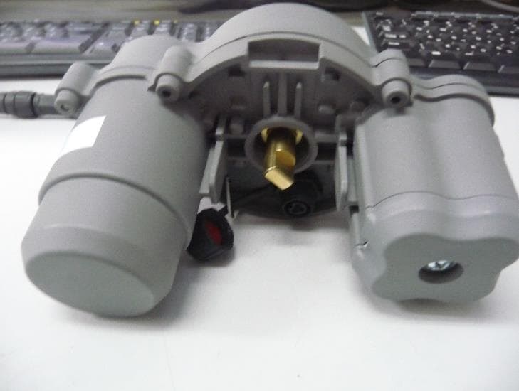
2AFOICBMSHLR5
Jul 03, 2024Shut Off Actuator
Equipment Class
DSS - Part 15 Spread Spectrum Transmitter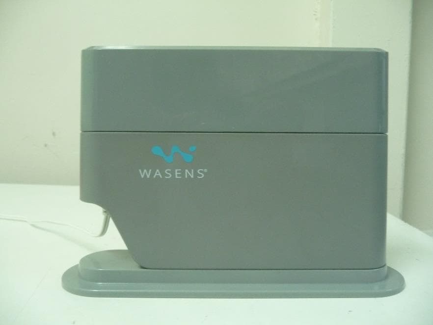
2AFOICBMCOLR5
Jul 03, 2024Controller
Equipment Class
DSS - Part 15 Spread Spectrum Transmitter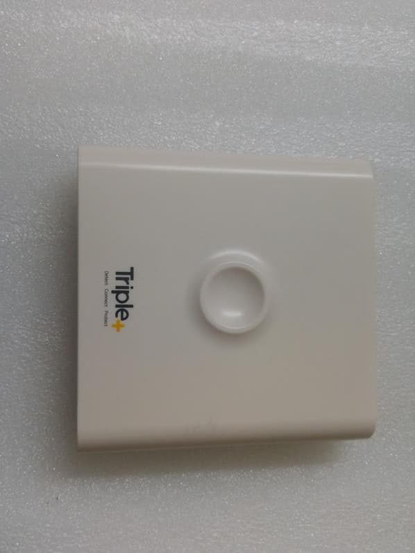
2AFOICIC
Apr 10, 2020Irrigation Controller
Equipment Class
DSC - Part 15 Security/Remote Control Transmitter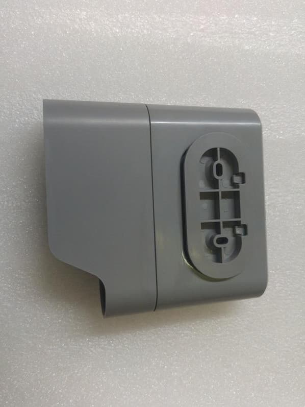
2AFOIHUB
Mar 04, 2020Hub
Equipment Class
DSC - Part 15 Security/Remote Control Transmitter