2AFOINGLVLWireless System for gas leakage detection and prevention
Triple Plus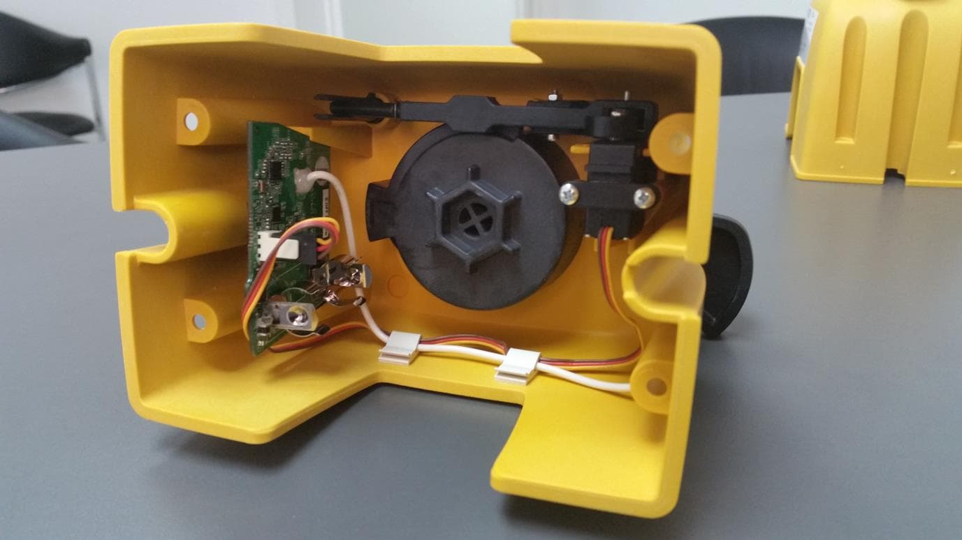
Click to zoom
Application Details
- Equipment Class
- DSR - Part 15 Remote Control/Security Device Transceiver
- Date of Grant
- Oct 25, 2015
- Application Purpose
- Original Equipment
- Date of Application
- Oct 25, 2015
- Equipment Note
- Wireless System for gas leakage detection and prevention
- Frequency Range
- 433.85000000 - 433.85000000
- Company
- Triple Plus
- Country
- Israel
Documents & Files
Document Text
Text extracted from the exhibit documents filed with the FCC. Open a document above to read the original.
Users Manual
NGL TM Gas Product Installa3on Instruc3ons NGL-INST-001E NGL TM Gas Product Installa3on Instruc3ons Compliance with regula3ons This product is intended exclusively for detec3on of liquefied petroleum gas (LPG) or natural gas (NG.) It should not be used for detec3on of other gases or fire. Complies with standards FCC | CE | EN 50194 | EN 50270 | EN 300 | EN 301 | ISO9001. System descrip3on The NGL TM wireless detec3on and preven3on system was designed to detect gas leakage and shut down the gas supply by way of wireless communica3on. Each installa3on may include up to 6 different detectors with one that would be defined during the detec3on as main detector (MASTER) and one Shut-‐off unit to be installed on an exis3ng gas valve. 1. Shut-‐off unit. 2. Adapter between the Shut-‐off unit and the gas valve. 3. Gas detector 4. CR123 baYery 5. Installa3on Instruc3ons. Content of the package 1 2 3 4 5 1. Green lamp means that the detector is properly ac3vated and opera3ve and indicates statuses of weak baYery. 2. A red light indicates a gas leak detec3on. 3. A green communica3on light indicates the existence of proper communica3on between the detector and the Shut-‐off unit. 4. Test buYon. 5. Audible Alarm 6. Mains supply (Use a designated AC/DC adapter) Detector descrip3on 1. Main gas unit 2. Adapter (to be installed in the main gas unit.) 3. Manual opening/ closing handle. 4. BuYon for manual release to "Closed" state. 5. BaYery cover (not presented.) Descrip3on of the Shut-‐off unit 2 1 3 4 Installa3on of the detector(s) The loca3on of the gas detector depends of the type of gas used. BeYer communica3on can be achieved by maintaining a direct line of sight between the various system components. Before performing the installa3on, please note the detector loca3on recommenda3ons: Natural gas is lighter than air, hence the detector should be located over the topmost window or door aperture, but no more than 30 cm beneath the ceiling level. Liquefied petroleum gas (LPG) is heavier than air, hence the detector should be located below the level where a poten3al gas leak may occur and no more than 30 cm above floor level. The NG or LPG detector should be located 1 to 4 meters from the gas device. System installa3on • In a closet or in any closed compound. • Where unit ven3la3on may be obstructed by curtains or furniture. • Where dirt and dust may accumulate and block the sensor, preven3ng its opera3on. • Where there is humidity and moisture. • Directly over cooking installa3ons. • Directly over sinks. • By a door, window or any other place that may be subject to drads such as an air extrac3on fan or ven3la3on aperture. • Anywhere out of a structure. • Where temperatures may drop below zero degrees cen3grade or exceed 55 degrees cen3grade. • Where it may be subject to impact or damage. • When the sensor is installed in an area with rough working condi3ons such as extra wet kitchens and laundry rooms, it should be protected by a transparent plas3c case with holes at its boYom. Places where the detector should NOT be posi3oned 1. Locate a power outlet complying with the requirements of sefng up a detector. Make sure that the electric cable of the adapter can be freely aYached in the loca3on desired for the detector. 2. Take the electric adapter and detector out of the box. 3. Remove the detector mount. 4. Posi3on the mount on the wall. 5. Mark the mount's two holes on the wall. 6. Drill two holes, using a wood or concrete drill or used drywall studs. 7. AYach the detector's mount to the wall using 2 x 5 mm screws. 8. AYach the detector onto the mount and turn it slightly to the right un3l it is locked into its place. 9. This is how the result should be. 10. Connect the detector to the power outlet and ensure that all 3 LED lights turn on and a clear beep sound is heard. 11. For the 3me being, un3l the Shut-‐off unit is installed, disconnect the power. Detector installa3on stages 8 9 10 The efficiency of the system relies of the quality of communica3on. BeYer communica3on can be achieved by maintaining a direct line of sight between the components. The Shut-‐off unit should not be installed in closed metal cases, as it may reduce the effec3ve range of communica3on. Shut-‐off unit installa3on stages Connec3on of the valve to the base unit Dismantling of the original valve unit Shut-‐off unit installa3on ASaching the base unit to a wall Installa3on of the 1/2" -‐ 3/8" adapter Inser3ng the baSery and the LED indicator Installa3on of the valve front unit and performing a manual test Synchroniza3on of the Shut-‐off unit with the network and the connected detectors is essen3al to proper opera3on of the system and prevents random opera3on by adjacent systems. Read carefully the instruc3ons and follow them precisely: Coordina3on of the communica3on ID No. of the Shut-‐off unit with the detectors is part of this process. A 10-‐minute set 3me is defined within the system to enable comple3on of the synchroniza3on process. The first detector to be installed is the main detector (MASTER). We recommend posi3oning the master detector closest to the Shut-‐off unit and the most visual rela3ve to it. The process will commence upon installa3on of the baYery within the Shut-‐off unit. System's component synchroniza3on and ac3va3on Opera3on/ indica3on OPERATION Indica3on 1 Inser3on of a baYery into the Shut-‐off unit • Ac3va3on of a green LED light. • The engine rotates by 180 degrees. 2 Connec3on of the main detector (MASTER) • Three LED lights light up for 2 seconds. • A beep sound is heard. • Only the Power LED is led ac3ve. 3 Detec3on of the main detector (SLAVE) • All LED lights blink once. • The Power and COM lights remain ac3ve. 4 Connec3on of the remaining detectors (SLAVE) • The LED light of each detector will blink according to its posi3on in the installa3on sequence. • The Power and COM lights remain ac3ve in each iden3fied detector. 5 Synchroniza3on of the system (Ac3ve) -‐ ader the last detector …
Text truncated - open the document above for the full version.
Cover Letter(s)
Triple Detect. Connect.Protect. Request forConfidentiality Date:Se pt1.2015 Subject: Confident iality Re q ue st for:2AFOINGLVL Purs uant toFCC47 CRF O.457(d)and0.459andIeRSP-I OO, Section10,theapplicantrequestst hatapartofthesubjec tFCCa pplica tio n be held confidential. TypeofConfid entialityRequestedExhib it DSho rtTermr8JPermanent BlockDiagr am s DSho rt Te rm External Phot o s DShortTe rm Internal Phot o s DShortTe rm [gJPermanent Operat ion Descript ion/T heory ofOperation DShortTerm oPermanentPartsList&Placement/BOM DShortTermDPermanentTune-UpProcedure DShortTerm [gJPermanentSchemat ics DShortTerm Test Setup Phot os DShort TermDPerm anent " User's Manual "Note: TriplePlushas spentsubsta ntialeffortin developingth is productanditis one of thefir st of i t s kindin industry. Having the subjec tinf o rmat ion easilyavailableto"competition"wouldnegateth e adva ntagetheyhave achieved by developingthis product. Not pro tectingthedetailsof the designwi ll resultin financialhardship. Perm a nentConfidentiality: The applican trequeststhe exhibi tslist ed above aspermanent ly confidentia lbe permanently withheldfrompublicreviewduet o mat erials t hatcontaintradesecrets andproprietaryinformation n otcustomarily released tot he public. short-rermConfidentiality: The applicantrequests theexhibitsselect edaboveas shorttermconfidentia lbe withheldfrompublicviewfora periodof180 days fromthedat e ofth e GrantofEqu ipment Authorizat ionandpriorto marketing.Thisis to avoid prematurerelease of sensitive informa tionprio r t o marketingorreleaseof t heproduc t to thepublic.Applicantis alsoawarethatt hey areresponsibletonot ify ACB in t heeventi nformationregardin g thep rod uct or theproductis made availableto the public. ACB will then release the documents listed abovefor public disclo surepursuantto FCCPublicNotfceDA 04-1705. NOTE forIndustryCanadaApplications: Theapplicant understand st hat until such timethat IedistinguishesbetweenShortTerm andPermanentConfidentia lity,eit hertypeof markedexhibitabove will simplybe marke dConfiden ti alwhen subm i ttedtoIC. ttz tkM archandBy: Sincerely,/]/ \.~ill\c4JLab ,I (SignatureITitle') 5 Hamada5t, Sout h Hi-Tee Park, Yoknea m2069200P.D.S 507, Israel i Tel : +972.72.2211370Iwww .tripleplus.io
External Photos
2.72.2211370 | www.tripleplus.io, Yokneam 2069200 P.O.B 507, Israel | Tel: +97Tec Park-South Hi ,5 Hamada St 2.72.2211370 | www.tripleplus.io, Yokneam 2069200 P.O.B 507, Israel | Tel: +97Tec Park-South Hi ,5 Hamada St 2.72.2211370 | www.tripleplus.io, Yokneam 2069200 P.O.B 507, Israel | Tel: +97Tec Park-South Hi ,5 Hamada St 2.72.2211370 | www.tripleplus.io, Yokneam 2069200 P.O.B 507, Israel | Tel: +97Tec Park-South Hi ,5 Hamada St
ID Label/Location Info
Labels Artwork Valve ,FCC ID: 2AFOI NGLVL Label #1: Label #2:
ID Label/Location Info
Label Location Valve,FCC ID: 2AFOI NGLVL
Internal Photos
5 Hamada St, South Hi-Tec Park, Yokneam 2069200 P.O.B 507, Israel | Tel: +972.72.2211370 | www.tripleplus.io 5 Hamada St, South Hi-Tec Park, Yokneam 2069200 P.O.B 507, Israel | Tel: +972.72.2211370 | www.tripleplus.io
Test Report
Electromagnetic Compatibility Test Report Test Report No: NLK 270114 Issued on: January 27, 2014 Product Name NGL System Gas Valve Unit Tested According to FCC 47 CFR, Part 15B & C Tests Performed for Nleak Technologies Ltd. Hatachana 42 Street, Binyamina 30500, Israel Tel +972 722211371 QualiTech EMC Laboratory 30 Hasivim Street,P.O.Box 7500 Petah-Tikva, 4951169, Israel Tel: +972-3-926 8443 Fax: +972-3-928 7490 Test Report: NLK 270114 Date: 27.01.2014 Rev. 1 Nleak Technologies Ltd. Page 2 of 29 NGL System EMC Lab The information contained herein is the property of QualiTech, EMC Lab and is supplied without liability for errors or omissions. The copyright for this document vests in QualiTech, EMC Lab. All rights reserved. This Test Report may not be reproduced, by any method, without the written permission of the QualiTech, EMC Lab. If and when such permission is granted, the report must be reproduced only in the full format. Test Personnel Tests Performed By: ---------------------------------------- Dmitry Isaev Report Prepared By: ------------------------------------- Bina Talkar Report Reviewed By: ------------------------------------- Rami Nataf EMC Lab. Manager QualiTech EMC Laboratory Test Report: NLK 270114 Date: 27.01.2014 Rev. 1 Nleak Technologies Ltd. Page 3 of 29 NGL System EMC Lab Test Report Details: Test commencement date: 01.01.2014 Test completion date: 21.01.2014 Customer’s representative: Menachem Liberman Issued on: 27.01.2014 Assessment Information: This report contains an assessment of the EUT against Electromagnetic Compatibility based upon tests carried out on the samples submitted. The results contained in this report relate only to the items tested. Manufactured products will not necessarily give identical results due to production and measurement tolerances. QualiTech, EMC Lab does not assume responsibility for any conclusion and generalization drawn from the test results with regards to other specimens or samples of type of the equipment represented by test item. The EUT was setup and exercised using the configuration, modes of operation and arrangements defined in this report only. Modifications: Modifications made to the EUT None Modifications made to the Test Standard None Test Report: NLK 270114 Date: 27.01.2014 Rev. 1 Nleak Technologies Ltd. Page 4 of 29 NGL System EMC Lab Summary of Compliance Status: FCC Part 15, Subpart C Part 15.249 – Intentional Radiators Test Spec. Clause Test Case Remarks FCC Part 15, Subpart B and C – Unintentional and Intentional Radiators 47 CFR §15.231(b) Field Strength of Fundamental and Spurious emission Pass 47 CFR §15.109 Radiated Emission, Unintentional Radiator Pass 47 CFR §15.107, §15.207 Conducted Emissions Pass 47 CFR §15.203 Antenna Connector requirement Pass 47 CFR §15.231(c) Occupied bandwidth Pass Test Report: NLK 270114 Date: 27.01.2014 Rev. 1 Nleak Technologies Ltd. Page 5 of 29 NGL System EMC Lab Table of Contents 1. GENERAL DESCRIPTION ................................................................................................................................................ 6 1.1. Description of the EUT /test Item: ................................................................................................... 6 2. METHOD OF MEASUREMENTS ..................................................................................................................................... 8 2.1. Radiated Emissions Measurements in the restricted bands: ............................................................. 8 2.2. Radiated Field Strength Measurements: ........................................................................................... 8 2.3. Conducted Measurement: ................................................................................................................. 8 2.4. Radiated Emission measurements: ................................................................................................... 8 3. REPORT OF MEASUREMENTS AND EXAMINATIONS ............................................................................................ 9 3.1. Field Strength Emission of Fundamental and Spurious Emission.................................................... 9 3.2. Radiated Emission, Unintentional Radiator ................................................................................... 19 3.3. Antenna Connector Requirements .................................................................................................. 24 3.4. Occupied bandwidth ....................................................................................................................... 25 4. APPENDIX .......................................................................................................................................................................... 27 Test Report: NLK 270114 Date: 27.01.2014 Rev. 1 Nleak Technologies Ltd. Page 6 of 29 NGL System EMC Lab 1. General Description 1.1. Description of the EUT /test Item: Product name: Gas Valve Unit FCC ID:2AFOINGLVL EUT Description- Triple+ NGLTM Shut off Unit housing is made of fire safety- retardant, reinforced Nylon. It includes a spring activated mechanism that is battery operated. The system also includes an on board controller and a primary RF communication layer. Triple+ NGLTM Shut off Unit is available for EN 331 certified ball valves 3/8” to 1”. This unit is assembled in-line with existing gas system. If a gas ball valve is installed, there is no need to cut, replace or remove existing pipelines or valves. There is no requirement for electrical outlet. The instant a triggering event is detected by one of the detectors, the main gas valve will be shut off. Test Report: NLK 270114 Date: 27.01.2014 Rev. 1 Nleak Technologies Ltd. Page 7 of 29 NGL System EMC Lab Shut off Specifications Dimensions [mm] 110(H)X145(L)X100W mm Clearance for handle add 10mm Weight 375gr Power 3V Lithium battery (CR123) Operating temperature 0C ÷ 50C, 32F ÷ 122F RH humidity 20%…
Text truncated - open the document above for the full version.
Test Setup Photos
Exhibit –Test Setup Photographs- FCC ID:2AFOINGLVL Photograph 1- Radiated spurious emission measurements below 30 MHz test setup Photograph 2- Radiated spurious emission measurements above 30 MHz – 1 GHz test setup FCC ID:2AFOINGLVL Photograph 3- Radiated spurious emission measurements 1 GHz – 6 GHz test setup
Contact Information
Applicant
Michael Isakov(CEO)
Test Firm
QualiTechTeodor Weisz
Technical Specifications
| # | Rule Parts | Frequency Range | Power Output |
|---|---|---|---|
| 1 | 15.231 | 433.85 MHz - 433.85 MHz | - |
Other Applications from Triple Plus
2AFOICBMUSLR5
Jul 03, 2024Flood family
Equipment Class
DSS - Part 15 Spread Spectrum Transmitter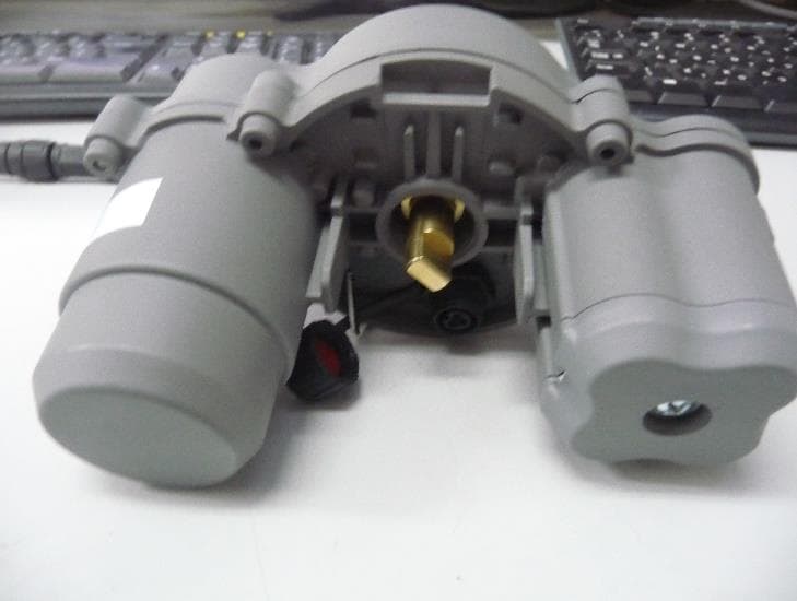
2AFOICBMSHLR5
Jul 03, 2024Shut Off Actuator
Equipment Class
DSS - Part 15 Spread Spectrum Transmitter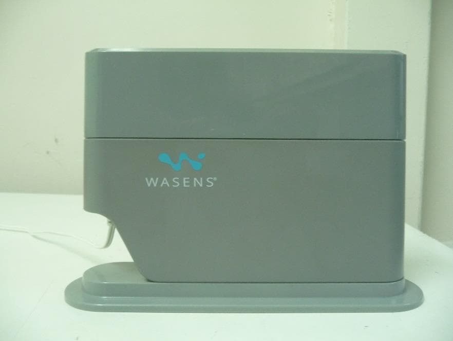
2AFOICBMCOLR5
Jul 03, 2024Controller
Equipment Class
DSS - Part 15 Spread Spectrum Transmitter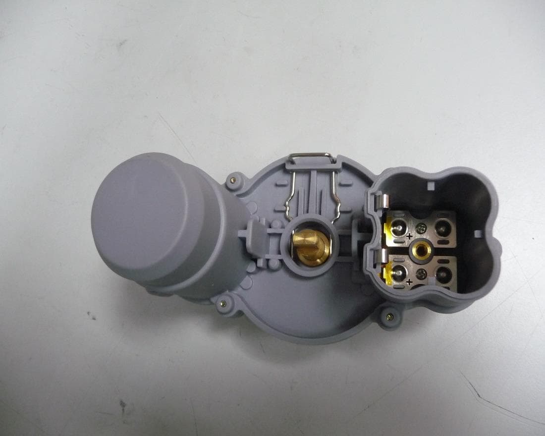
2AFOILORA
Jun 01, 2020LoRa based Ball valve Actuator security system
Equipment Class
DTS - Digital Transmission System
2AFOICIC
Apr 10, 2020Irrigation Controller
Equipment Class
DSC - Part 15 Security/Remote Control Transmitter