2AFOINWLFDFlood detector of Water leakage security system
Triple Plus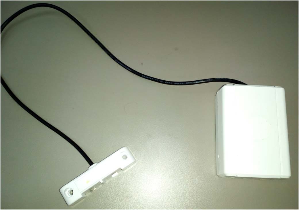
Click to zoom
Application Details
- Equipment Class
- DSR - Part 15 Remote Control/Security Device Transceiver
- Date of Grant
- Jan 04, 2016
- Application Purpose
- Original Equipment
- Date of Application
- Jan 04, 2016
- Equipment Note
- Flood detector of Water leakage security system
- Frequency Range
- 433.85000000 - 433.85000000
- Company
- Triple Plus
- Country
- Israel
Documents & Files
Document Text
Text extracted from the exhibit documents filed with the FCC. Open a document above to read the original.
Users Manual
User’s Manual Water Product TM NWL NWL-TRN-001 Flooding Detection System BackgroundTriple+ wireless NWL ™ (No Water Leak) system is designed to detect water leaks and prevent the subsequent damages. The system shuts do wn the water supply by way of a wireless communication system.The system's objective is to minimize potential flo oding damages by shutting down the water supply when there is no activity and/or a flo oding is indicated within the system. Each system is comprised of a Shut Off unit (valve) , installed on the main water supply pipe, a flood detector and a control unit for closi ng and opening the valve. The system presents the user with a clear and simple indication of the valve's status (either open or closed.) In addition, the Shut Off unit can be controlled (and thus, the valve can be opened or closed) manually. Shut Off unit (valve ) A Shut Off unit 3/4" (Sagiv valve) is installed on the main water supply pipe with the intention of allowing or preventing water from passing through the pipes. System specification 1. Opening/ closing handle.1A. Open/ closed indication.2. Shut Off unit body (valve).3. 3/4" entry/exit adapter.4. Base for a valve not wall mounted.4A. Base for a wall mounted valve.5. 2XCR123 battery housing • The Shut Off unit should be located on the main wa ter line leading into the structure. The system should not disconnect a fire extinguishi ng line or a sprinkler line. • Ensure easy access to the battery housing.• The unit should be installed with the handle on to p and horizontally placed • To provide effective communication, ensure to have no more than 12 meters (if a wall is present within the structure) or 30 meters wi thin an open space structure between the controller and the valve and that the u nits (controller and valve) are not positioned within metal cabinets. If the above is pr oblematic, consider setting up a relay (repeater). Shut Off unit installation • Within a metal cabinet• Where dirt or a foreign object may obstruct the va lve's operation. • Where the temperature exceeds the range between 0 and 55 degrees centigrade. • Where there is an apprehension of being hit or dam aged. • In an external place where exposed to rain and dir ect sunlight and/or to the elements, the unit should be installed in a waterti ght plastic casing. • In humid environment Places where the detector should NOT be positioned 1. Locate the most suitable place for installation o n the water line. 2. Shut down the water supply, using the main valve of the building or site. 3. Dismantle the water line connectors in a way that would leave a gap suitable for installing the valve . 4. Install the unit on the water line.5. Should a flexible water pipe be required to mount the Shut Off unit on the wall, dismantle the base unit. 6. Make sure that the Shut Off unit can be opened and closed manually. 7. Enable passage of water in the main line and prev ent leaks or drippings. 8. Ensure easy access to the battery housing.9. If unit wetting is probable, install an external protective casing. Shut Off unit installation stages The button controller allows the user to trigger the wireless opening and closing of the valve manually.In addition, there is an option of a direct connect ion to an alarm system. In this case the closure of the valve will be synchronized with t he alarm triggering. Controller unit 3A 3B 1A 1B 1C3D 3C 4 5 1A. Valve closing button.1B. Technician button.1C. Valve opening button3A. Water battery indicator5. 5VDC power input3B. Water valve indicator.3C. Communications light.3D. Voltage indicator4. Alarm wiring connector System synchronization: valve - controller synchronization table OPERATION Location Control indication 1 I. Shift the valve handle to the open position. II. Insert two CR123 batteries into the Shut Off unit (valve.) A water valve that is installed on the main water line I. A green indicator lights up within the battery ho using. II. The valve performs an opening action and then a closing one. III. Wait for the conclusion of the engine's operati on. IV. Ensure that the valve can be manually opened and closed. 2 Hook the controller to the main supply with the transformer. Position the controller where measurements indicate qualitative and continuous transmission. I. The four indicators flash 3 times. II. The voltage indicator flashes. III. Wait for approximately two minutes by the contr oller to ensure that the communication indicator is lit continuously (in add ition to the flashing voltage indicator.) In case the communication indicator flashes or is t urned off, a repeater should be installed within the system. 3 Press the technician button Controller After some th irty seconds, all four indicators will flash. The voltage and communication indicators are contin uously on. After another thirty seconds, the open valve indica tor indicates the valve's state (open or closed.) 4 Synchronization test: open and close the valve using the buttons Controller Check that the valve opens and closes acc ordingly. Make sure that the open valve indicator indicates t he valve's state (open or closed.) OPERATION Location Control indication 1 I. Shift the valve handle to the open position. II. Insert two CR123 batteries into the disconnection unit (valve.) A water valve that is installed on the main water line I. A green indicator lights up within the battery ho using. II. The valve performs an opening action and then a closing one. III. Wait for the conclusion of the engine's operati on. IV. Ensure that the valve can be manually opened and closed. 2 Hook the repeater to the main supply with the transformer. Position the repeater where measurements indicate qualitative and continuous transmission. The four indicators flash 3 times. The voltage indicator flashes. Wait for approximately two minutes by the repeater to ensure that the indicator of communication with the valve is lit co ntinuously (in addition to the flashing voltage indicator.)In case the communicat…
Text truncated - open the document above for the full version.
External Photos
TriplePlus Ltd. FCC ID:2AFOINWLFD IC:20798-NWLFD Page 1 of 5 EXTERNAL PHOTOGRAPHS This document contains 4 photographs TriplePlus Ltd. FCC ID:2AFOINWLFD IC:20798-NWLFD Page 2 of 5 Photograph No.1 Flood detector front view TriplePlus Ltd. FCC ID:2AFOINWLFD IC:20798-NWLFD Page 3 of 5 Photograph No.2 Flood detector rear side view TriplePlus Ltd. FCC ID:2AFOINWLFD IC:20798-NWLFD Page 4 of 5 Photograph No.3 Flood detector side view TriplePlus Ltd. FCC ID:2AFOINWLFD IC:20798-NWLFD Page 5 of 5 Photograph No.4 Flood detector top view
ID Label/Location Info
Triple Plus Ltd. FCC ID:2AFOINWLFD IC:20798-NWLFD Page 1 of 2 Label Triple Plus Ltd. FCC ID:2AFOINWLFD IC:20798-NWLFD Page 2 of 2 Label location Label with FCC ID:2AFOINWLFD and IC:20798-NWLFD is located at the rear side panel of the Controller/Repeater unit. The statement according to FCC part 15 §15.19(a)(3) is placed in User’s Manual, page 19 (Application exhibit User_manual_27396). FCC ID: 2AFOINWLFD IC: 20798-NWLFD
Internal Photos
TriplePlus Ltd. FCC ID:2AFOINWLFD IC:20798-NWLFD Page 1 of 4 INTERNAL PHOTOGRAPHS This document contains 3 photographs TriplePlus Ltd. FCC ID:2AFOINWLFD IC:20798-NWLFD Page 2 of 4 3 Photograph No.1 Flood detector internal view TriplePlus Ltd. FCC ID:2AFOINWLFD IC:20798-NWLFD Page 3 of 4 Photograph No.2 Flood detector PCB front view TriplePlus Ltd. FCC ID:2AFOINWLFD IC:20798-NWLFD Page 4 of 4 Photograph No.3 Flood detector PCB front view
Test Report
Hermon Laboratories Ltd. Harakevet Industrial Zone, Binyamina 30500, Israel Tel. +972-4-6288001 Fax. +972-4-6288277 E-mail: [email protected] Page 1 of 44 Report ID: TRIRAD_FCC.27396.docx Date of Issue: 10-Dec-15 ELECTRICAL TESTING 0839.01 TEST REPORT ACCORDING TO: FCC CFR 47 Part 15 subpart C, section 15.231 and subpart B RSS-210 issue 8 Annex 1, ICES-003 Issue 5:2012 FOR: Triple Plus Ltd. Flood detector of Water leakage security system Model: NWL-DETFLD-6-01 FCC ID:2AFOINWLFD IC:20798-NWLFD This report is in conformity with ISO/ IEC 17025. The "A2LA Accredited" symbol endorsement applies only to the tests and calibrations that are listed in the scope of Hermon Laboratories accreditation. The test results relate only to the items tested. This test report shall not be reproduced in any form except in full with the written approval of Hermon Laboratories Ltd. Report ID: TRIRAD_FCC.27396.docx Date of Issue: 10-Dec-15 Page 2 of 44 Table of contents 1 Applicant information ..................................................................................................................................................... 3 2 Equipment under test attributes .................................................................................................................................... 3 3 Manufacturer information .............................................................................................................................................. 3 4 Test details .................................................................................................................................................................... 3 5 Tests summary .............................................................................................................................................................. 4 6 EUT description ............................................................................................................................................................. 5 6.1 General information ....................................................................................................................................................... 5 6.2 Test configuration .......................................................................................................................................................... 5 6.3 Changes made in EUT .................................................................................................................................................. 5 6.4 EUT test positions ......................................................................................................................................................... 5 6.5 Transmitter characteristics ............................................................................................................................................ 6 7 Transmitter tests according to 47CFR part 15 subpart C requirements ........................................................................ 7 7.1 Periodic operation requirements ................................................................................................................................... 7 7.2 Field strength of emissions .......................................................................................................................................... 12 7.3 Occupied bandwidth test ............................................................................................................................................. 25 7.4 Antenna requirements ................................................................................................................................................. 28 8 Unintentional emissions .............................................................................................................................................. 29 8.1 Radiated emission measurements .............................................................................................................................. 29 9 APPENDIX A Test equipment and ancillaries used for tests ....................................................................................... 35 10 APPENDIX B Measurement uncertainties ................................................................................................................... 36 11 APPENDIX C Test laboratory description ................................................................................................................... 37 12 APPENDIX D Specification references ....................................................................................................................... 37 13 APPENDIX E Test equipment correction factors ......................................................................................................... 38 14 APPENDIX F Abbreviations and acronyms ................................................................................................................. 44 Report ID: TRIRAD_FCC.27396.docx Date of Issue: 10-Dec-15 Page 3 of 44 1 Applicant information Client name: Triple Plus Ltd. Address: 5 Hamada street, Yokneam 2069200, Israel Telephone: +972 72 211 7711 E-mail: [email protected] Contact name: Mr. Itzik Marchand 2 Equipment under test attributes Product name: Flood Detector of Water leakage security system Product type: Transceiver Model(s): NWL-DETFLD-6-01 Serial number: 01 Hardware version: 01 Software release: 4.0 Receipt date 06-Sep-15 3 Manufacturer information Manufacturer name: Triple Plus Ltd. Address: 5 Hamada street, Yokneam 2069200, Israel Telephone: +972 72 211 7711 E-Mail: [email protected] Contact name: Mr. Itzik Marchand 4 Test details Project ID: 27396 Location: Hermon Laboratories Ltd. Harakevet Industrial Zone, Binyamina 30500, Israel Test started: 08-Sep-15 Test completed: 10-Sep-15 Test specification(s): FCC 47CFR part 15, subpart C, §15.231 and subpart B; RSS-210 issue 8 An…
Text truncated - open the document above for the full version.
Test Setup Photos
Triple Plus Ltd. FCC ID:2AFOINWLFD IC:20798-NWLFD Page 1 of 6 SETUP PHOTOGRAPHS This document contains 5 photographs Triple Plus Ltd. FCC ID:2AFOINWLFD IC:20798-NWLFD Page 2 of 6 Photograph No.1 Setup for spurious emission field strength measurements in the anechoic chamber below 30 MHz Triple Plus Ltd. FCC ID:2AFOINWLFD IC:20798-NWLFD Page 3 of 6 Photograph No.2 Setup for carrier, spurious emission field strength measurements in the anechoic chamber in 30 – 1000 MHz range Triple Plus Ltd. FCC ID:2AFOINWLFD IC:20798-NWLFD Page 4 of 6 Photograph No.3 Setup for spurious emission field strength measurements in the anechoic chamber above 1000 MHz range Triple Plus Ltd. FCC ID:2AFOINWLFD IC:20798-NWLFD Page 5 of 6 Photograph No.4 Setup for spurious emission field strength measurements in the anechoic chamber, EUT close view Triple Plus Ltd. FCC ID:2AFOINWLFD IC:20798-NWLFD Page 6 of 6 Photograph No.5 Setup for transmitter shut down test and occupied bandwidth measurements
Contact Information
Applicant
Oren Niv(CTO)
Technical Contact
Hermon Laboratories Ltd.Michael Nikishin
[email protected]97246268440
Harakevet Industrial zone, P.O.Box 23 · Israel
Non-Technical Contact
Triple Plus Ltd.Itzik Marchand
[email protected]972722211370
Test Firm
Hermon Laboratories Ltd.Alexander Usoskin
Technical Specifications
| # | Rule Parts | Frequency Range | Power Output |
|---|---|---|---|
| 1 | 15.231 | 433.85 MHz - 433.85 MHz | - |
Other Applications from Triple Plus
2AFOICBMUSLR5
Jul 03, 2024Flood family
Equipment Class
DSS - Part 15 Spread Spectrum Transmitter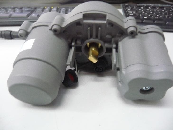
2AFOICBMSHLR5
Jul 03, 2024Shut Off Actuator
Equipment Class
DSS - Part 15 Spread Spectrum Transmitter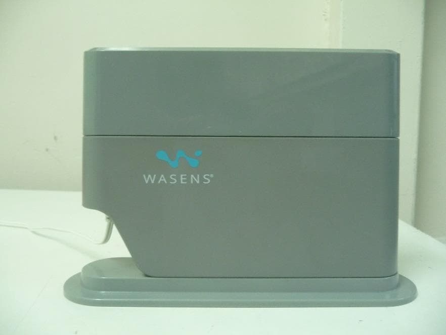
2AFOICBMCOLR5
Jul 03, 2024Controller
Equipment Class
DSS - Part 15 Spread Spectrum Transmitter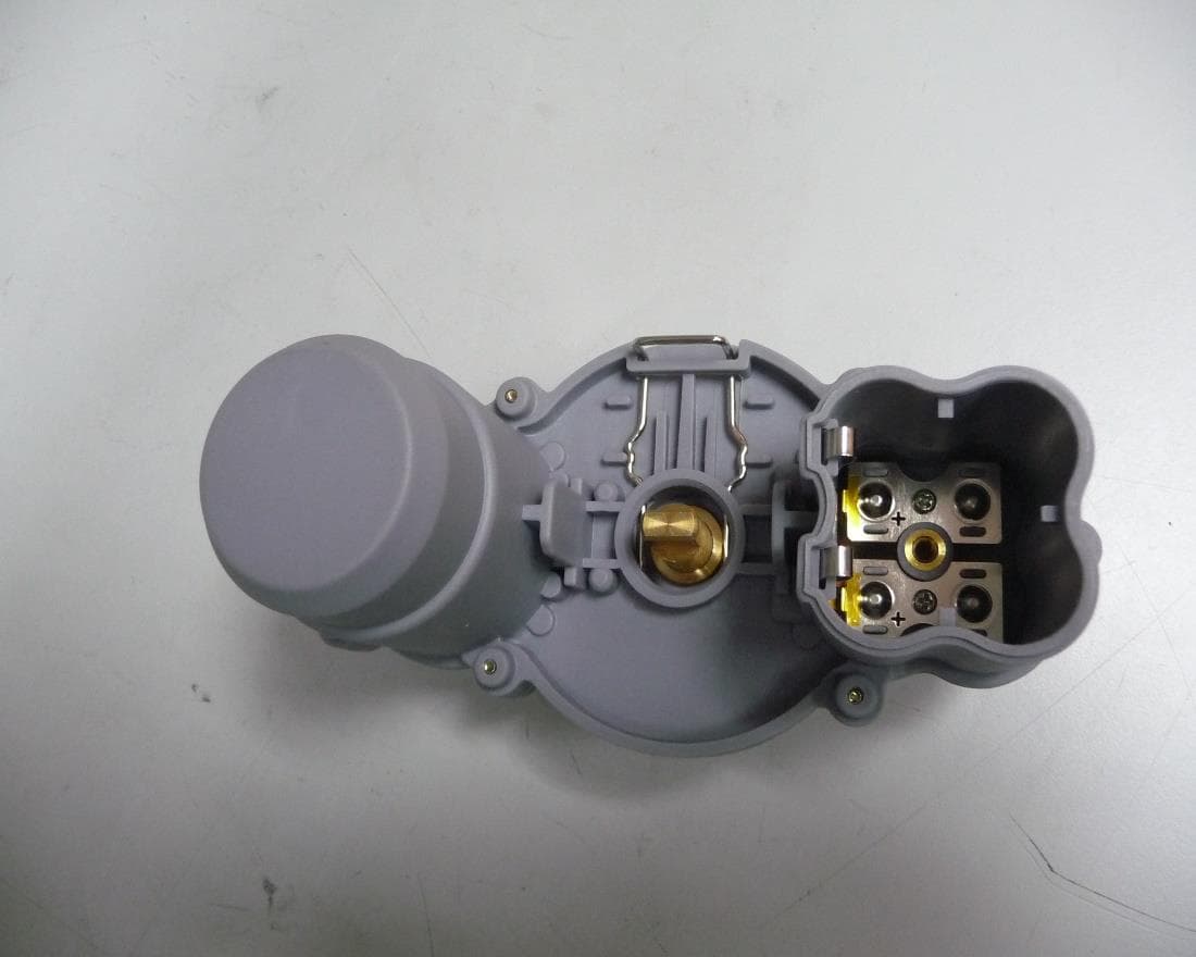
2AFOILORA
Jun 01, 2020LoRa based Ball valve Actuator security system
Equipment Class
DTS - Digital Transmission System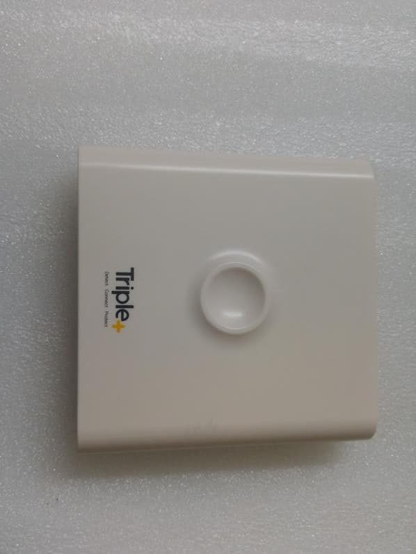
2AFOICIC
Apr 10, 2020Irrigation Controller
Equipment Class
DSC - Part 15 Security/Remote Control Transmitter