2AG7X-V30All-in-one VR
Shenzhen Hengbida Electronic Technology Co., Ltd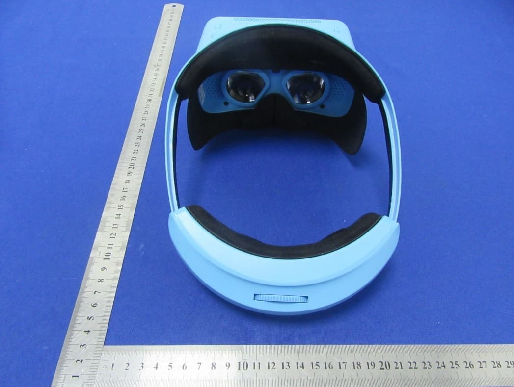
Click to zoom
Application Details
- Equipment Class
- DSS - Part 15 Spread Spectrum Transmitter
- Date of Grant
- Nov 01, 2020
- Application Purpose
- Original Equipment
- Date of Application
- Nov 01, 2020
- Equipment Note
- All-in-one VR
- Frequency Range
- 2402.00000000 - 2480.00000000
- Country
- China
Documents & Files
Document Text
Text extracted from the exhibit documents filed with the FCC. Open a document above to read the original.
Users Manual
1.This warranty applies to V3000000000 VR device. 1. Warranty card............................................................. 2. Any man-made damage caused by the sale of the 2.Vulnerable accessories such as power adapters are one, if ther e are any malfunction caused from the 1, Welcome and thank you for choosing VR All-in- a new one,and the validity of maintenance is 1 year. retumed,in 15 days, the devicecan be exchanged for 7 days since the purchase, the device can be specified maintenance office or the sales agency. In quality issues, please send the device back to the pano360, you can click the menu option downon the rightand then switch the patterns. Volume adjustment:Press up/down button to the video starts to play, please exit the playmode and start again. adjust the volume a. If there is a new version available online, then it can be downloaded and updated directly. Notice:When the paired devices cannot be connected cancel it and try again. photos, setting and other statuses displaying such as,battery level, time, accessed devices and wireless on the main menu. The calibrat ion of Gyroscope will seconds, and ther e will be 6 main application icons be working after pressing on the menu button for 5 part without falling. When you need to continue in dependently up, and it will be set in the upper watching you can rotate the VR independently down 2.6 Media play er ....................................................... 4 3、FAQ and solutions: ................................................ 2.8 All applications .................................................... 2.7 Applic ation store .................................................. 2.5.4 System ............................................................... 2.5.3 General ............................................................... 2.5.2 Bluetooth .......................................................... 2.5.1 Wireless network .............................................. 2.5 Settings ................................................................ 2.4. Home page ......................................................... 2.3 HMD ...................................................................... 2.2 S teps for usage ................................................... 2.1 F unction keys instruction ................................... 2. Operation guideline .............................................. 1. Notice ..................................................................... 12 11 10 9 8 8 7 4 4 3 User Manual Dear Cust omers Thank you for choosing and using VR products. High quality and high performance are the char- acteristics that VR products possess. For better usage, please read the manual, and follow the operation st- eps. If you have any questions, please contact us in reference to the number and address listed in the warranty card, we’ll be at your service. VR-sincerity always for you! Directory User manual 1. NOTICE 2. OPERATION GUIDELINE 2.1. Function k eys instruction A cknowledgement key Return key Power button Menu (N) key Headb and Battery Headband knob Light perception Indic ator light USBUSB HOST vInt erface TF Headset R eset key 2.2 Steps for usage: 1.T ake out the machine 2.2.1 Long press the power button 紧 松 Long press 2.2.2 Put on the VR all-in-one machine, adjust to the appropriate position, the viewing angle is facing the all-in machine, the picture is cle- arly displayed 2.2.3 Rotate the headband knob to adjust the tightness of the headband Clockwise: TightlyCounterclockwise: Loose 2.2.4 When the eye is tired, it can rotate the VR body Viewing time R est time 2.3 HMD 1)The HMD will be pow ered on after around 40 seconds. 2) The white dot is subject to gyro function, and can be used as the mouse cursor, Press the confirmation key to enter the functional interface for confirmation, or the Back button to back to the former directory. 2.4. Home page The main menu includes local applications, online cinema, panorama view of OL, VR bar ofsinging, network. 2.5 Settings Setting options include Wi-Fi, Bluetooth, General, System, Connecting external devices. 2.5.1 Wir eless network Scan for available wireless networks , choose the wireless network and enter the password to connect. 2.5.2 Bluetooth When the Bluetooth is turned on, then it will automa tically search for devices and come up a listof devices which can be connect ed. 2.5.3 General The adjustment o f the screen brightness, the settings o f the volume, language, dormancy time,and time zone are all included. 2.5.4 System System update, factory reset and about device, these 3 parts are included.Methods for system update: b. Transfer the downloaded software into local file, and then update it manually. About devices:User can check the system version, machine hardware/software parameters. 2.6 Media play er Play er includes local video and online video section. Select the video:Using paired remote control or buttons on the mini host to select the video Play video:After the video is selected, press the OK button to play Pause video:Press the OK button when the video is playing to pause Fast forward/fast backward:Move the cursor, and then press OK button Exit play mode:Press the Back button Remarks: If the dual screen mode appeared when 2.7 Application st ore User c an download and install games and other applications from app market via Wi-Fi. 2.8 All applications All o f the games, applications installed will be displ- ayed in the option of all applications. Users can manage these installed applications. Click on the icon of delete down on the right,and then the selected application can be uninstalled. 3、F AQ AND SOLUTIONS: 1) The device cannot be p owered on:Please ensur e that y ou have press and hold the power butt onfor 3 seconds, and check the b attery status 2) The splash scr een happens once the applicat ion is ent ered: back to the previous directory andtry again. 3) There are three patterns in VR video: 2D、3D、 P acking list No. No. Quant i…
Text truncated - open the document above for the full version.
Cover Letter(s)
Shenzhen Hengbida Electronic Technology co., Ltd Agent Authorization Company: Shenzhen Hengbida Electronic Technology co., Ltd Address: Building D, 4/F, Shanghe Industrial Park Nanchang Rd, Xixiang Street, Ban’an District, Shenzhen, China Product Name: All-in-one VR Model Number(s): V30, V20, V22, V23, V31, V32, V33, V40, V41, V42, V43, V50, V51, V52, V53, V60, V61, V62, V63, A01, A02, A03, A04, A05, A06, A07, A08, A09, A10 Trademark: N/A FCC ID: 2AG7X-V30 We authorize MiCOM Labs Inc., 575 Boulder Court, Pleasanton, California 94566, USA, to act on our behalf on all matters concerning the certification of above named equipment. We declare that MiCOM Labs Inc. is allowed to forward all information related to the approval and certification of equipment to the regulatory agencies as required and to discuss any issues concerning the approval application. Any and all acts carried out by MiCOM Labs on our behalf shall have the same effect as acts of our own. Signature: Date: 2020/10/26 Name: Jianxi Liu Title: Manager Company: Shenzhen Hengbida Electronic Technology co., Ltd
Cover Letter(s)
Shenzhen Hengbida Electronic Technology co., Ltd Office of Engineering Technology Federal Communications Commission 7435 Oakland Mills Road Columbia, MD 21046 USA Date: 2020/10/26 Subject; Request for Confidentiality FCC ID: 2AG7X-V30 To Whom It May Concern, Pursuant to the provisions of the Commission’s rules Title 47 Sections §0.457 and §0.459, we are requesting the Commission to withhold the following attachment(s) as confidential documents from public disclosure indefinitely. These documents contain detailed system and equipment descriptions and are considered as proprietary information in operation of the equipment. The public disclosure of these documents might be harmful to our company and would give competitors an unfair advantage in the market. Schematic Diagram Block Diagram Operational Description SOFTWARE SECURITY REQUIREMENTS FOR U-NII DEVICES In additional to above mentioned documents, in order to comply with the marketing regulations in Title 47 CFR §2.803 and the importation rules in Title 47 CFR §2.1204, while ensuring that business sensitive information remains confidential until the actual marketing of newly authorized devices, we request Short Term Confidentiality of the following attachment(s); User Manual For 45 days, pursuant to Public Notice DA 04-1705. OR For 180 days pursuantto KDB 726920 D01. It is our understanding that all measurement test reports, FCC ID label format and correspondence during the certification review process cannot be granted as confidential documents and this information will be available for public review once the grant of equipment authorization is issued. Sincerely, Signature: Name: Jianxi Liu Title: Manager
Cover Letter(s)
Shenzhen Hengbida Electronic Technology co., Ltd Model Difference 2020.10.26 Product Name: All-in-one VR Model Number(s): V30, V20, V22, V23, V31, V32, V33, V40, V41, V42, V43, V50, V51, V52, V53, V60, V61, V62, V63, A01, A02, A03, A04, A05, A06, A07, A08, A09, A10 Trademark: N/A FCC ID: 2AG7X-V30 All the model are the same circuit and RF module, except model names. Regards Sincerely Client’s signature: Client’s name / title : Jianxi Liu / Manager Contact information / address: Building D, 4/F, Shanghe Industrial Park Nanchang Rd, Xixiang Street, Ban’an District, Shenzhen, China
External Photos
External Photos
ID Label/Location Info
Size:30*15mm FCC ID: 2AG7X-V30 This device complies with Part 15 of the FCC Rules. Operation is subject to the following two conditions:(1)This device may not cause harmful interfer ence, and (2) this device must accept any interference received, including interference that may cause undesired operation. Label Location
Internal Photos
Internal Photos Antenna
RF Exposure Info
FCC ID: 2AG7X-V30 Portable device According to §47 C.F.R. and §2.1093, systems operating under the provisions of this section shall be operated in a manner that ensures that the public is not exposed to radio frequency energy level in excess of the Commission’s guidelines. According to KDB447498 D01 General RF Exposure Guidance V06 The 1-g SAR and 10-g SAR test exclusion thresholds for 100 MHz to 6 GHz at test separation distances ≤ 50 mm are determined by: [(max. power of channel, including tune-up tolerance, mW) / (min. test separation distance, mm)]·[√f(GHz)/x] W/kg, for test separation distances ≤ 50 mm, Where x = 7.5 for 1-g SAR and x = 18.75 for 10-g SAR • f(GHZ) is the RF channel transmit frequency in GHz • Power and distance are rounded to the nearest mW and mm before calculation • The result is rounded to one decimal place for comparison When the minimum test separation distance is < 5 mm, a distance of 5 mm and x = 7.5 for 1-g SAR is applied to determine SAR test exclusion. BT-EDR Modulation Channel Freq. (GHz) Conduct ed power (dBm) Conducte d power (mW) Tune-up power (dBm) Max tune-up power (dBm) Max tune-up power (mW) Distance (mm) Result calculatio n SAR Exclusion threshold SAR test exclusion GFSK2.480-1.880.65-1±10.001.00<50.041990.40YES Pi/4 DQPSK 2.402-0.5940.87-0±11.001.26<50.052030.40YES 8DPSK2.441-0.3590.92-0±11.001.26<50.052450.40YES BT-BLE Modulation Channel Freq. (GHz) Conduct ed power (dBm) Conducte d power (mW) Tune-up power (dBm) Max tune-up power (dBm) Max tune-up power (mW) Distance (mm) Result calculatio n SAR Exclusion threshold SAR test exclusion GFSK2.4020.391.090±11.001.26<50.052030.40YES 2.4G-WIFI Modulation Channel Freq. (GHz) Conduct ed power (dBm) Conducte d power (mW) Tune-up power (dBm) Max tune-up power (dBm) Max tune-up power (mW) Distance (mm) Result calculatio n SAR Exclusion threshold SAR test exclusion 2.4374.702.955±16.003.98<50.165730.40YES 802.11b 5G-WIFI Modulation Channel Freq. (GHz) Conducte d power (dBm) Conducte d power (mW) Tune-up power (dBm) Max tune-up power (dBm) Max tune-up power (mW) Distanc e (mm) Result calculation SAR Exclusion threshold SAR test exclusion 5.1805.803.805±16.003.98<50.241620.40YES 802.11a 5.8G-WIFI Modulation Channel Freq. (GHz) Conducte d power (dBm) Conducte d power (mW) Tune-up power (dBm) Max tune-up power (dBm) Max tune-up power (mW) Distance (mm) Result calculatio n SAR Exclusion threshold SAR test exclusion 5.5805.613.645±16.003.98<50.250780.40YES 802.11n20 For the Max simultaneous transmission Conclusion: For the max result : 0.30323 <0.4, the SAR testing is not required. Evaluation mode Result calculation Total Result calculation SAR Exclusion threshold Result 2.4G-WIFI 0.16573 0.21818 0.4 Pass BT 0.05245 Evaluation mode Result calculation Total Result calculation SAR Exclusion threshold Result 5G-WIFI 0.24162 0.29407 0.4 Pass BT 0.05245 Evaluation mode Result calculation Total Result calculation SAR Exclusion threshold Result 5.8G-WIFI 0.25078 0.30323 0.4 Pass BT 0.05245
Test Report
ReportNo.: BCTC2008003313-1E No.:BCTC/RF-EMC-005Page:34of68Edition:A.1 Pi/4 DQPSK Transmitting Band edge-right side Pi/4 DQPSK Hopping Band edge-right side ReportNo.: BCTC2008003313-1E No.:BCTC/RF-EMC-005Page:35of68Edition:A.1 8DPSK Transmitting Band edge-left side 8DPSK Hopping Band edge-left side ReportNo.: BCTC2008003313-1E No.:BCTC/RF-EMC-005Page:36of68Edition:A.1 8DPSK Transmitting Band edge-right side 8DPSK Hopping Band edge-right side ReportNo.: BCTC2008003313-1E No.:BCTC/RF-EMC-005Page:37of68Edition:A.1 10. 20 DB BANDWIDTH 10.1 Block Diagram Of Test Setup 10.2 Limit N/A 10.3 Test procedure 1. Set RBW = 30kHz. 2. Set the video bandwidth (VBW) ≥ 3 x RBW. 3. Detector = Peak. 4. Trace mode = max hold. 5. Sweep = auto couple. 6. Allow the trace to stabilize. 7. Measure the maximum width of the emission that is constrained by the frequencies associated with the two outermost amplitude points (upper and lower frequencies) that are attenuated by 6 dB relative to the maximum level measured in the fundamental emission. . ReportNo.: BCTC2008003313-1E No.:BCTC/RF-EMC-005Page:38of68Edition:A.1 10.4 Test Result Temperature: 26°C Relative Humidity: 54% Test Voltage : DC 3.8V Remark N/A Modulation Test Channel Bandwidth(MHz) GFSK Low 0.930 GFSK Middle 0.897 GFSK High 0.895 Pi/4 DQPSK Low 1.285 Pi/4 DQPSK Middle 1.285 Pi/4 DQPSK High 1.287 8DPSK Low 1.231 8DPSK Middle 1.227 8DPSK High 1.230 Test plots GFSK Low Channel ReportNo.: BCTC2008003313-1E No.:BCTC/RF-EMC-005Page:39of68Edition:A.1 GFSK Middle Channel GFSK High Channel ReportNo.: BCTC2008003313-1E No.:BCTC/RF-EMC-005Page:40of68Edition:A.1 Pi/4 DQPSK Low Channel Pi/4 DQPSK Middle Channel ReportNo.: BCTC2008003313-1E No.:BCTC/RF-EMC-005Page:41of68Edition:A.1 Pi/4 DQPSK High Channel 8DPSK Low Channel ReportNo.: BCTC2008003313-1E No.:BCTC/RF-EMC-005Page:42of68Edition:A.1 8DPSK Middle Channel 8DPSK High Channel ReportNo.: BCTC2008003313-1E No.:BCTC/RF-EMC-005Page:43of68Edition:A.1 11. MAXIMUM PEAK OUTPUT POWER 11.1 Block Diagram Of Test Setup 11.2 Limit FCC Part15 (15.247) , Subpart C Section Test Item Limit Frequency Range (MHz) Result 15.247(b)(1) Peak Output Power 0.125 watt or 21dBm 2400-2483.5 PASS 11.3 Test procedure 1. Remove the antenna from the EUT and then connect a low RF cable from the antenna port to the spectrum. 2. Set the spectrum analyzer: RBW = 3MHz. VBW = 3MHz. Sweep = auto; Detector Function = Peak. 3. Keep the EUT in transmitting at lowest, medium and highest channel individually. Record the max value. ReportNo.: BCTC2008003313-1E No.:BCTC/RF-EMC-005Page:44of68Edition:A.1 11.4 Test Result Temperature: 26°C Relative Humidity: 54% Test Voltage : DC 3.8V Remark: N/A Modulation Test Channel Output Power (dBm) Limit (dBm) GFSK Low -1.905 21 GFSK Middle -1.920 21 GFSK High -1.880 21 Pi/4 DQPSK Low -0.594 21 Pi/4 DQPSK Middle -0.614 21 Pi/4 DQPSK High -0.678 21 8DPSK Low -0.380 21 8DPSK Middle -0.359 21 8DPSK High -0.391 21 Test plots GFSK Low Channel ReportNo.: BCTC2008003313-1E No.:BCTC/RF-EMC-005Page:45of68Edition:A.1 GFSK Middle Channel GFSK High Channel ReportNo.: BCTC2008003313-1E No.:BCTC/RF-EMC-005Page:46of68Edition:A.1 Pi/4 DQPSK Low Channel Pi/4 DQPSK Middle Channel ReportNo.: BCTC2008003313-1E No.:BCTC/RF-EMC-005Page:47of68Edition:A.1 Pi/4 DQPSK High Channel 8DPSK Low Channel ReportNo.: BCTC2008003313-1E No.:BCTC/RF-EMC-005Page:48of68Edition:A.1 8DPSK Middle Channel 8DPSK High Channel ReportNo.: BCTC2008003313-1E No.:BCTC/RF-EMC-005Page:49of68Edition:A.1 12. HOPPING CHANNEL SEPARATION 12.1 Block Diagram Of Test Setup 12.2 Limit Frequency hopping systems shall have hopping channel carrier frequencies separated by a minimum of 25 kHz or the 20 dB bandwidth of the hopping channel, whichever is greater. Alternatively, frequency hopping systems operating in the 2400-2483.5 MHz band may have hopping channel carrier frequencies that are separated by 25 kHz or two-thirds of the 20 dB bandwidth of the hopping channel, whichever is greater, provided the systems operate with an output power no greater than 0.125W. 12.3 Test procedure 1. Remove the antenna from the EUT and then connect a low RF cable from the antenna port to the spectrum. 2. Set the spectrum analyzer: RBW = 30kHz. VBW = 100kHz , Span = 2.0MHz. Sweep = auto; Detector Function = Peak. Trace = Max hold. 3. Allow the trace to stabilize. Use the marker-delta function to determine the separation between the peaks of the adjacent channels. The limit is specified in one of the subparagraphs of this Section Submit this plot. ReportNo.: BCTC2008003313-1E No.:BCTC/RF-EMC-005Page:50of68Edition:A.1 12.4 Test Result Modulation Test Channel Separation (MHz) Limit(MHz) Result GFSK Low 0.996 0.620 PASS GFSK Middle 0.994 0.598 PASS GFSK High 0.988 0.597 PASS Pi/4 DQPSK Low 1.000 0.857 PASS Pi/4 DQPSK Middle 1.010 0.857 PASS Pi/4 DQPSK High 0.996 0.858 PASS 8DPSK Low 0.998 0.821 PASS 8DPSK Middle 1.002 0.818 PASS 8DPSK High 1.004 0.820 PASS Test plots GFSK Low Channel ReportNo.: BCTC2008003313-1E No.:BCTC/RF-EMC-005Page:51of68Edition:A.1 GFSK Middle Channel GFSK High Channel ReportNo.: BCTC2008003313-1E No.:BCTC/RF-EMC…
Text truncated - open the document above for the full version.
Test Report
ReportNo.: BCTC2008003313-1E No.:BCTC/RF-EMC-005Page:56of68Edition:A.1 13.4 Test Result Test Plots: 79 Channels in total GFSK Pi/4 DQPSK ReportNo.: BCTC2008003313-1E No.:BCTC/RF-EMC-005Page:57of68Edition:A.1 8DPSK ReportNo.: BCTC2008003313-1E No.:BCTC/RF-EMC-005Page:58of68Edition:A.1 14. DWELL TIME 14.1 Block Diagram Of Test Setup 14.2 Limit Frequency hopping systems in the 2400-2483.5 MHz band shall use at least 15 channels. The average time of occupancy on any channel shall not be greater than 0.4 seconds within a period of 0.4 seconds multiplied by the number of hopping channels employed. Frequency hopping systems may avoid or suppress transmissions on a particular hopping frequency provided that a minimum of 15 channels are used. 14.3 Test procedure 1. Remove the antenna from the EUT and then connect a low RF cable from the antenna port to the spectrum. 2. Set spectrum analyzer span = 0. Centred on a hopping channel; 3. Set RBW = 1MHz and VBW = 3MHz.Sweep = as necessary to capture the entire dwell time per hopping channel. Set the EUT for DH5, DH3 and DH1 packet transmitting. 4. Use the marker-delta function to determine the dwell time. If this value varies with different modes of operation (e.g.. data rate. modulation format. etc.). repeat this test for each variation. The limit is specified in one of the subparagraphs of this Section. Submit this plot(s). ReportNo.: BCTC2008003313-1E No.:BCTC/RF-EMC-005Page:59of68Edition:A.1 14.4 Test Result DH5 Packet permit maximum 1600 / 79 / 6 hops per second in each channel (5 time slots RX, 1 time slot TX). DH3 Packet permit maximum 1600 / 79 / 4 hops per second in each channel (3 time slots RX, 1 time slot TX). DH1 Packet permit maximum 1600 / 79 /2 hops per second in each channel (1 time slot RX, 1 time slot TX). So, the Dwell Time can be calculated as follows: DH5:1600/79/6*0.4*79*(MkrDelta)/1000 DH3:1600/79/4*0.4*79*(MkrDelta)/1000 DH1:1600/79/2*0.4*79*(MkrDelta)/1000 Remark: Mkr Delta is once pulse time. Modulation Channel Data Packet pulse time(ms) Dwell Time(s) Limits(s) GFSK Middle DH1 0.410 0.131 0.4 DH3 1.674 0.268 0.4 DH5 2.940 0.314 0.4 Pi/4DQPSK Middle 2DH1 0.422 0.135 0.4 2DH3 1.692 0.271 0.4 2DH5 2.940 0.314 0.4 8DPSK Middle 3DH1 0.422 0.135 0.4 3DH3 1.680 0.269 0.4 3DH5 2.950 0.315 0.4 Test Plots GFSK DH1 Middle Channel ReportNo.: BCTC2008003313-1E No.:BCTC/RF-EMC-005Page:60of68Edition:A.1 GFSK DH3 Middle Channel GFSK DH5 High Middle Channel ReportNo.: BCTC2008003313-1E No.:BCTC/RF-EMC-005Page:61of68Edition:A.1 Pi/4DQPSK DH1 Middle Channel Pi/4DQPSK DH3 Middle Channel ReportNo.: BCTC2008003313-1E No.:BCTC/RF-EMC-005Page:62of68Edition:A.1 Pi/4DQPSK DH5 Middle Channel 8DPSK DH1 Middle Channel ReportNo.: BCTC2008003313-1E No.:BCTC/RF-EMC-005Page:63of68Edition:A.1 8DPSK DH3 Middle Channel 8DPSK DH5 Middle Channel ReportNo.: BCTC2008003313-1E No.:BCTC/RF-EMC-005Page:64of68Edition:A.1 15. ANTENNA REQUIREMENT 15.1 Limit 15.203 requirement: For intentional device, according to 15.203: an intentional radiator shall be designed to ensure that no antenna other than that furnished by the responsible party shall be used with the device. 15.2 Test Result The EUT antenna is Internal antenna, fulfill the requirement of this section. ReportNo.: BCTC2008003313-1E No.:BCTC/RF-EMC-005Page:65of68Edition:A.1 16. EUT PHOTOGRAPHS EUT Photo 1 EUT Photo 2 ReportNo.: BCTC2008003313-1E No.:BCTC/RF-EMC-005Page:66of68Edition:A.1 17. EUT TEST SETUP PHOTOGRAPHS Conducted emissions ReportNo.: BCTC2008003313-1E No.:BCTC/RF-EMC-005Page:67of68Edition:A.1 Radiated Measurement Photos ReportNo.: BCTC2008003313-1E No.:BCTC/RF-EMC-005Page:68of68Edition:A.1 STATEMENT 1.Theequipmentlistsaretraceabletothenationalreferencestandards. 2.Thetestreportcannotbepartiallycopiedunlesspriorwrittenapprovalisissuedfromourlab. 3.Thetestreportisinvalidwithoutstampoflaboratory. 4.Thetestreportisinvalidwithoutsignatureofperson(s)testingandauthorizing. 5.ThetestprocessandtestresultisonlyrelatedtotheUnitUnderTest. 6.ThequalitysystemofourlaboratoryisinaccordancewithISO/IEC17025. 7.Ifthereisanyobjectiontoreport,theclientshouldinformissuinglaboratorywithin15days fromthedateofreceivingtestreport. Address: 1-2F,EastofBBuilding,PengzhouIndustrialPark,Fuyuan1stRoad,Qiaotou,FuyongStreet,Ba o'anDistrict,Shenzhen,Guangdong,China TEL:400-788-9558 P. C.:518103 FAX:0755-33229357 Website:http://www.bctc-lab.com E-Mail:[email protected] ※※※※※ END ※※※※※
Test Setup Photos
Conducted emissions Radiated Measurement Photos
Contact Information
Applicant
Jianxi Liu(Manager)
Technical Contact
Test Firm
Shenzhen BCTC Testing Co., Ltd.Sally He
[email protected]15999690624
Technical Specifications
| # | Rule Parts | Frequency Range | Power Output |
|---|---|---|---|
| 1 | 15C | 2.40 GHz - 2.48 GHz | 920.00 µW |
Other Applications from Shenzhen Hengbida Electronic Technology Co., Ltd
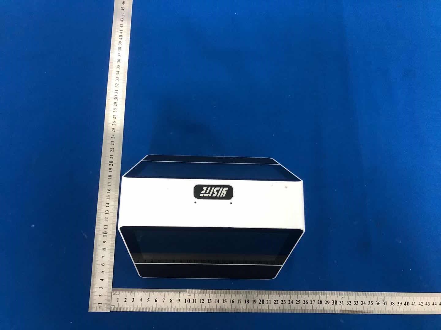
2AG7X-XF4
Nov 17, 2020Double screen translator
Equipment Class
DSS - Part 15 Spread Spectrum Transmitter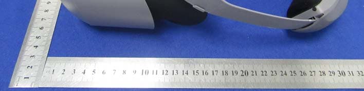
2AG7X-V21
Oct 08, 2020All-in-one VR
Equipment Class
NII - Unlicensed National Information Infrastructure TX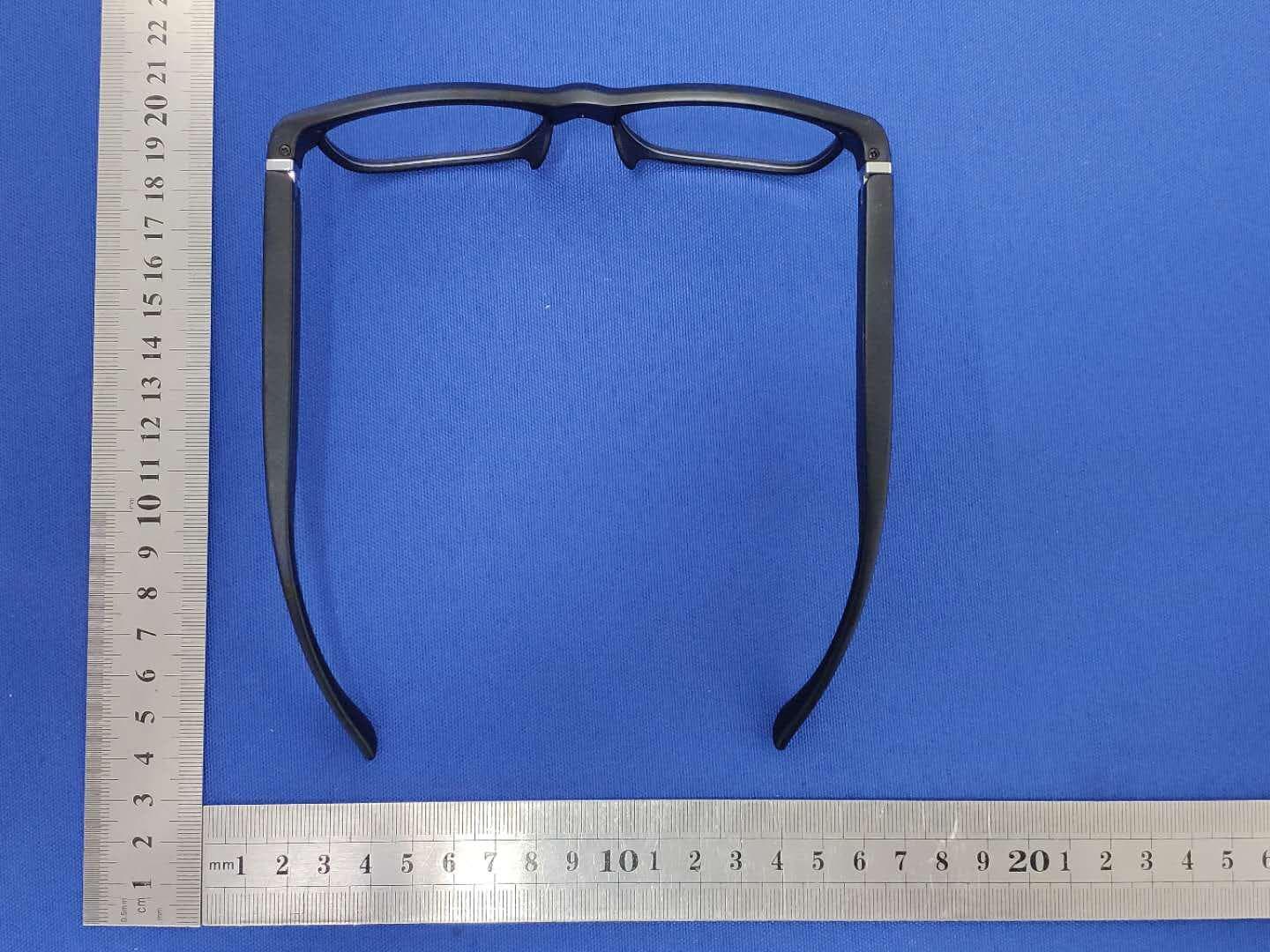
2AG7X-ZY1
Aug 31, 2020AI CLASSES
Equipment Class
DTS - Digital Transmission System
2AG7X-XF3
Aug 23, 2020Translation bar
Equipment Class
DSS - Part 15 Spread Spectrum Transmitter