2AGN9-BEGPS5500Bad Elf Flex
Bad Elf, LLC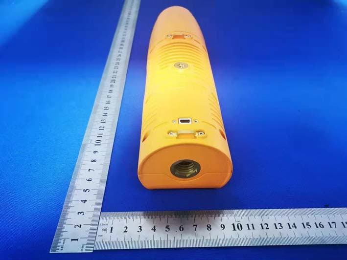
Click to zoom
Application Details
- Equipment Class
- DSS - Part 15 Spread Spectrum Transmitter
- Date of Grant
- Apr 22, 2020
- Application Purpose
- Original Equipment
- Date of Application
- Apr 22, 2020
- Equipment Note
- Bad Elf Flex
- Frequency Range
- 2402.00000000 - 2480.00000000
- Company
- Bad Elf, LLC
- Country
- United States
Documents & Files
Document Text
Text extracted from the exhibit documents filed with the FCC. Open a document above to read the original.
Users Manual
Bad Elf Flex User Manual Introduction The Bad Elf Flex is an external GNSS receiver designed for field data collection when paired with a mobile phone or tablet. The hardware supports several configurations including multi-constellation, multi-frequency, and L-Band reception. Product Overview What’s in the box The following items are included in the standard Flex configuration: ●Rugged carrying case ●Bad Elf Flex ●Wall charger ●Vehicle charger ●1m USB charging cable ●USB OTG adapter cable ●Pole mount adapter ●Quick start guide Supported devices You can connect a Flex receiver to a handheld device, phone, or tablet powered by the following operating systems: ●iOS version 11 or newer ●Android versions 4.1x or newer ●Windows 10.x or newer ●Mac OS X 10.4 or newer Using the Bad Elf Flex We’ve designed the Flex to be as simple and intuitive as possible. Charging the Bad Elf Flex ●How to charge & charge indicators ●Operation while charging ●Compatible chargers ●Temperature - charge limitations ●Low battery - device behavior Turning on and off the receiver To turn the receiver on, press and hold the power button for 3 seconds. The Flex will take approximately 20 seconds to start up and begin looking for satellites. To turn the receiver off, press and hold the power button for 3 seconds. Status information (LCD & LEDs) The LCD display is the primary user interface of the Flex accessory The LEDs are used to display information at-a-glance. Their function changes depending on what mode you are in. The LCD screen will usually have a label or key that indicates what each LED represents. By default, the LEDs are configured to show the following status information: Left LED Power status Center LED User configurable. Default: shows GNSS navigation status Right LED User configurable. Default: shows Bluetooth connection status The power status LED is used to indicate the battery, charging, and operating status. Color Meaning Solid Green Fully charged Flashing Green Charging Red Battery Low Flashing Red Battery critically low Connecting your mobile device via Bluetooth The following steps will help you connect your mobile phone or tablet to the Flex receiver via Bluetooth. Start by making sure you Flex is turned on, and within range of your phone or tablet. Then follow the instructions below: For iPhone and iPad devices running iOS ●On your iOS Device, open the Settings app and navigate to the Bluetooth screen. ●If needed, turn Bluetooth on. ●If you have not previously paired with this Bad Elf Flex, it will appear in the “Other Devices” section. Tap the Flex in the list to start the pairing process. You may be prompted to confirm the pairing on both your mobile device and ●Once you are paired, the Flex will appear in the My Devices section. If the status shows as Disconnected, you can tap the Flex name to initiate a connection. ●Once the pairing and connection succeeds, you should see it listed as Connected in the list of devices on your iOS device. For Android phones and tablets To pair the Flex with your Android device: 1.On your Android device, go to Settings > Wireless & Networks. Make sure Bluetooth is turned on. 2.Go to Settings > Wireless & Networks > Bluetooth Settings and tap Scan for devices. 3.After a few seconds, the Flex should appear in the list of available Bluetooth devices. 4.Tap the name in the list and to start the pairing process. You may be prompted on both your Android device and Flex to confirm the pairing. 5.Once paired, you usually see the Flex show up in the list as Connected for a few seconds, before switched to Disconnected. This is normal. The Bluetooth connection will be opened/closed by whatever apps are using it. For Windows To pair the Flex with your Windows computer please follow the instructions below. This process will only have to be done once and does not need to be repeated in the future. 1.Select Bluetooth Devices from the icon list in the lower right hand portion of your desktop. 2.Note, the Bluetooth option may not be displayed. If not click the up arrow. 3.If your Bad Elf accessory is turned on, you should see something like BE5500-12345678 (with your unit's serial number) in the list. 4.Select your Bad Elf receiver from the list, and tap the Pair button. 5.Within 5-10 seconds, you should see a prompt from windows showing pairing is complete. Once this action is completed, the message “Ready to pair” will change to “Paired” as shown below. At this point you have successfully paired your Bad Elf receiver with your Windows computer. Next, you will need to determine the COM port assigned by the operating system. To accomplish this: 1.Click on the icon to the left of the Bad Elf GPS #XXXXXXX 2.Click on “More Bluetooth Options” 3.A Bluetooth settings dialog will open 4.Click on the “COM Ports” tab 5.The COM port with your device serial number labeled as “Outgoing” is the COM port you should use for your application. Connecting your computer via USB Use the supplied Micro-USB cable to connect the Bad Elf Flex to your desktop or laptop computer. Once properly connect you will see the charging indicator come on if the Flex is not fully charged. Install companion app From your phone or tablet, visit http://bad-elf.com/app-flex to download the correct Bad Elf Flex companion app for your operating system. This app is used to check the health of your hardware, perform firmware upgrades, change settings, and stream correction data to your Bad Elf Flex. Using 3rd party apps Any location-based app on iOS or Android can be used with the Bad Elf Flex. You can visit http://bad-elf.com/apps for a list of compatible apps that we’ve either tested or have been recommended by other customers. Connecting an external GNSS antenna Only use an external antenna that is designed to be used with the Flex receiver. Ensure the antenna being connected does not exceed the voltage and current limits defined in the Flex product specifications. To connect an external antenna, remove the top cove…
Text truncated - open the document above for the full version.
Cover Letter(s)
Bad Elf, LLC Agent Authorization Company: Bad Elf, LLC Address: 41 Crossroads Plaza, Suite 110 West Hartford, CT 06117, USA Product Name: Bad Elf Flex Model Number(s ): BE-GPS-5500 Product Description: Bad Elf Flex We authorize MiCOM Labs Inc., 575 Boulder Court, Pleasanton, California 94566, USA, to act on our behalf on all matters concerning the certification of above named equipment. We declare that MiCOM Labs Inc. is allowed to forward all information related to the approval and certification of equipment to the regulatory agencies as required and to discuss any issues concerning the approval application. Any and all acts carried out by MiCOM Labs on our behalf shall have the same effect as acts of our own. Signature: Date: 2020/03/02 Name: J.Cunningham Title: Manager Company: Bad Elf, LLC
Cover Letter(s)
Bad Elf, LLC Office of Engineering Technology Federal Communications Commission 7435 Oakland Mills Road Columbia, MD 21046 USA Date: 2020/03/02 Subject; Request for Confidentiality FCC ID: 2AGN9-BEGPS5500 To Whom It May Concern, Pursuant to the provisions of the Commission’s rules Title 47 Sections §0.457 and §0.459, we are requesting the Commission to withhold the following attachment(s) as confidential documents from public disclosure indefinitely. These documents contain detailed system and equipment descriptions and are considered as proprietary information in operation of the equipment. The public disclosure of these documents might be harmful to our company and would give competitors an unfair advantage in the market. Schematic Diagram Block Diagram Operational Description In additional to above mentioned documents, in order to comply with the marketing regulations in Title 47 CFR §2.803 and the importation rules in Title 47 CFR §2.1204, while ensuring that business sensitive information remains confidential until the actual marketing of newly authorized devices, we request Short Term Confidentiality of the following attachment(s); User Manual For 45 days, pursuant to Public Notice DA 04-1705. OR For 180 days pursuantto KDB 726920 D01. It is our understanding that all measurement test reports, FCC ID label format and correspondence during the certification review process cannot be granted as confidential documents and this information will be available for public review once the grant of equipment authorization is issued. Sincerely, Signature: Name: J.Cunningham Title: Manager
External Photos
External Photos
ID Label/Location Info
Size:40*20mm M/N: BE-GPS-5500 FCC ID: 2AGN9-BEGPS5500 IC: 25807-BEGPS5500 This device complies with part 15 of the FCC Rules. Operation is subject to the following two conditions: (1) This device may not cause harmful interference, and (2) This device must accept any interference received, including interference that may cause undesired operation. Label location
Internal Photos
Internal Photos GPS Receiver Antenna BT/WIFI Antenna
RF Exposure Info
Model: BE-GPS-5500 Report No.: WTX20X03012942W Page 1 of 40 SAR Report FCC ID: 2AGN9-BEGPS5500 Test Standards: FCC Part 2.1093, ANSI / IEEE C95.1 :2005+A1:2010 ANSI / IEEE C95.3 :2002(R2008) Product Description: Bad Elf Flex Tested Model: BE-GPS-5500 Report No.: WTX20X03012942W Sample Received Date: Mar.25,2020 Tested Date: Mar.25,2020 to Apr.08,2020 Issued Date: Apr.08, 2020 Tested By: Jack Sun / Engineer Reviewed By: Lion Cai / RF Manager Approved & Authorized By: Silin Chen / EMC Manager Prepared By: Shenzhen SEM Test Technology Co., Ltd. 1/F, Building A, Hongwei Industrial Park, Liuxian 2nd Road, Bao'an District, Shenzhen, P.R.C.(518101) Tel.: +86-755-33663308 Fax.: +86-755-33663309 Website: www.semtest.com.cn Note: This test report is limited to the above client company and the product model only. It may not be duplicated without prior permitted by Shenzhen SEM Test Technology Co., Ltd. FCC SAR Measurement and Test Report For Bad Elf, LLC 41 Crossroads Plaza, Suite 110 West Hartford, CT 06117, USA Model: BE-GPS-5500 Report No.: WTX20X03012942W Page 2 of 40 SAR Report TABLE OF CONTENTS 1. General Information ................................................................................................................................................... 3 1.1 Product Description for Equipment Under Test (EUT) ......................................................................................... 3 1.2 Test Standards .................................................................................................................................................... 5 1.3 Test Methodology ................................................................................................................................................ 5 1.4 Test Facility ......................................................................................................................................................... 5 2. Summary of Test Results .......................................................................................................................................... 6 3. Specific Absorption Rate (SAR) ................................................................................................................................ 7 3.1 Introduction .......................................................................................................................................................... 7 3.2 SAR Definition ..................................................................................................................................................... 7 4. SAR Measurement System ........................................................................................................................................ 8 4.1 The Measurement System .................................................................................................................................. 8 4.2 Probe ................................................................................................................................................................... 8 4.3 Probe Calibration Process ................................................................................................................................. 10 4.4 Phantom ............................................................................................................................................................ 11 4.5 Device Holder .................................................................................................................................................... 11 4.6 Test Equipment List ........................................................................................................................................... 12 5. Tissue Simulating Liquids ....................................................................................................................................... 13 5.1 Composition of Tissue Simulating Liquid ........................................................................................................... 13 5.2 Tissue Dielectric Parameters for Head and Body Phantoms ............................................................................. 14 5.3 Tissue Calibration Result ................................................................................................................................... 15 6. SAR Measurement Evaluation ................................................................................................................................ 16 6.1 Purpose of System Performance Check ............................................................................................................ 16 6.2 System Setup .................................................................................................................................................... 16 6.3 Validation Results .............................................................................................................................................. 17 7. EUT Testing Position ............................................................................................................................................... 18 7.1 EUT Antenna Position ....................................................................................................................................... 18 7.2 EUT Testing Position ......................................................................................................................................... 19 8. SAR Measurement Procedures ............................................................................................................................... 20 8.1 Measurement Procedures ................................................................................................................................. 20 8.2 Spatial Peak SAR Evaluation ...........................................................................…
Text truncated - open the document above for the full version.
RF Exposure Info
Ref : ACR.233.1.17.SATU.A SHENZHEN SEM TEST TECHNOLOGY CO., LTD. 1/F, BUILDING A, HONGWEI INDUSTRIAL PARK, LIUXIAN 2ND ROAD BAO'AN DISTRICT SHENZHEN (518101), CHINA MVG COMOSAR DOSIMETRIC E-FIELD PROBE SERIAL NO.: SN 45/15 EPGO280 Calibrated at MVG US 2105 Barrett Park Dr. - Kennesaw, GA 30144 Calibration Date: 07/08/2019 Summary: This document presents the method and results from an accredited COMOSAR Dosimetric E-Field Probe calibration performed in MVG USA using the CALISAR / CALIBAIR test bench, for use with a COMOSAR system only. All calibration results are traceable to national metrology institutions. COMOSAR E-Field Probe Calibration Report COMOSAR E-FIELD PROBE CALIBRATION REPORT Ref: ACR.233.1.17.SATU.A Page: 2/10 This document shall not be reproduced, except in full or in part, without the written approval of MVG. The information contained herein is to be used only for the purpose for which it is submitted and is not to be released in whole or part without written approval of MVG. Name Function Date Signature Prepared by : Jérôme LUC Product Manager 7/8/2019 Checked by : Jérôme LUC Product Manager 7/8/2019 Approved by : Kim RUTKOWSKI Quality Manager 7/8/2019 Customer Name Distribution : Shenzhen SEM.Test Technology Co., Ltd. Issue Date Modifications A 7/8/2019 Initial release COMOSAR E-FIELD PROBE CALIBRATION REPORT Ref: ACR.233.1.17.SATU.A Page: 3/10 This document shall not be reproduced, except in full or in part, without the written approval of MVG. The information contained herein is to be used only for the purpose for which it is submitted and is not to be released in whole or part without written approval of MVG. TABLE OF CONTENTS 1 Device Under Test ..................................................................................................... 4 2 Product Description ................................................................................................... 4 2.1 General Information _______________________________________________________ 4 3 Measurement Method ................................................................................................ 4 3.1 Linearity ________________________________________________________________ 4 3.2 Sensitivity _______________________________________________________________ 5 3.3 Lower Detection Limit _____________________________________________________ 5 3.4 Isotropy _________________________________________________________________ 5 3.5 Boundary Effect __________________________________________________________ 5 4 Measurement Uncertainty .......................................................................................... 5 5 Calibration Measurement Results .............................................................................. 6 5.1 Sensitivity in air __________________________________________________________ 6 5.2 Linearity ________________________________________________________________ 7 5.3 Sensitivity in liquid ________________________________________________________ 7 5.4 Isotropy _________________________________________________________________ 8 6 List of Equipment .................................................................................................... 10 COMOSAR E-FIELD PROBE CALIBRATION REPORT Ref: ACR.233.1.17.SATU.A Page: 4/10 This document shall not be reproduced, except in full or in part, without the written approval of MVG. The information contained herein is to be used only for the purpose for which it is submitted and is not to be released in whole or part without written approval of MVG. 1 DEVICE UNDER TEST Device Under Test Device Type COMOSAR DOSIMETRIC E FIELD PROBE Manufacturer MVG Model SSE2 Serial Number SN 45/15 EPGO280 Product Condition (new / used) New Frequency Range of Probe 0.7 GHz-6GHz Resistance of Three Dipoles at Connector Dipole 1: R1=0.193 M Dipole 2: R2=0.188 M Dipole 3: R3=0.198 M A yearly calibration interval is recommended. 2 PRODUCT DESCRIPTION 2.1 GENERAL INFORMATION MVG’s COMOSAR E field Probes are built in accordance to the IEEE 1528, OET 65 Bulletin C and CEI/IEC 62209 standards. Figure 1 – MVG COMOSAR Dosimetric E field Dipole Probe Length 330 mm Length of Individual Dipoles 2 mm Maximum external diameter 8 mm Probe Tip External Diameter 2.5 mm Distance between dipoles / probe extremity 1 mm 3 MEASUREMENT METHOD The IEEE 1528, OET 65 Bulletin C, CENELEC EN50361 and CEI/IEC 62209 standards provide recommended practices for the probe calibrations, including the performance characteristics of interest and methods by which to assess their affect. All calibrations / measurements performed meet the fore mentioned standards. 3.1 LINEARITY The evaluation of the linearity was done in free space using the waveguide, performing a power sweep to cover the SAR range 0.01W/kg to 100W/kg. COMOSAR E-FIELD PROBE CALIBRATION REPORT Ref: ACR.233.1.17.SATU.A Page: 5/10 This document shall not be reproduced, except in full or in part, without the written approval of MVG. The information contained herein is to be used only for the purpose for which it is submitted and is not to be released in whole or part without written approval of MVG. 3.2 SENSITIVITY The sensitivity factors of the three dipoles were determined using a two step calibration method (air and tissue simulating liquid) using waveguides as outlined in the standards. 3.3 LOWER DETECTION LIMIT The lower detection limit was assessed using the same measurement set up as used for the linearity measurement. The required lower detection limit is 10 mW/kg. 3.4 ISOTROPY The axial isotropy was evaluated by exposing the probe to a reference wave from a standard dipole with the dipole mounted under the flat phantom in the test configuration suggested for system validations and checks. The probe was rotated along its main axis from 0 - 360 degrees in 15 degree steps. The hemispherical isotropy is determined by inserting the probe in a thin plastic box filled with tissue-equivalent liquid, with the plastic box …
Text truncated - open the document above for the full version.
Test Report
Shenzhen BCTC Testing Co., Ltd. Report No.: BCTC1912001439-2E FCC Part 15C Test Report FCC ID: 2AGN9-BEGPS5500 Product Name: Bad Elf Flex Trademark: Bad Elf Model Name : BE-GPS-5500 Prepared For : Bad Elf, LLC Address : 41 Crossroads Plaza, Suite 110 West Hartford, CT 06117, USA Prepared By : Shenzhen BCTC Testing Co., Ltd. Address : BCTC Building & 1-2F, East of B Building, Pengzhou Industrial, Fuyuan 1st Road, Qiaotou Community, Fuyong Street, Bao’an District, Shenzhen, China Test Date: Dec. 16, 2019 – Jan. 10, 2020 Date of Report : Jan. 10, 2020 Report No.: BCTC1912001439-2E Te s t Report Tel: 400-788-9558 Web: https://www.bctc-lab.com BCTC/RF-EMC-0 07 Ver.:A.0 Page 1 of 67 Shenzhen BCTC Testing Co., Ltd. Report No.: BCTC1912001439-2E TEST RESULT CERTIFICATION Applicant’s name ............. : Bad Elf, LLC Address .............................. : 41 Crossroads Plaza, Suite 110 West Hartford, CT 06117, USA Manufacture's Name ....... : Xiamen Weiyou Intelligent Technology Co., Ltd Address .............................. : Jimei District, in the northern industrial zone of Xiamen City, Fujian Province, China Product description Product name ..................... : Bad Elf Flex Trademark .......................... : Bad Elf Model and/or type reference ........................................... : BE-GPS-5500 Standards .......................... : FCC Part15.247 ANSI C63.10:2013 This device described above has been tested by BCTC, and the test results show that the equipment under test (EUT) is in compliance with the FCC requirements. And it is applicable only to the tested sample identified in the report. This report shall not be reproduced except in full, without the written approval of BCTC, this document may be altered or revised by BCTC, personal only, and shall be noted in the revision of the document. Prepared by(Engineer): Willem Wang Reviewer(Supervisor): Eric Yang Approved(Manager): Zero Zhou Te s t Report Tel: 400-788-9558 Web: https://www.bctc-lab.com BCTC/RF-EMC-0 07 Ver.:A.0 Page 2 of 67 Shenzhen BCTC Testing Co., Ltd. Report No.: BCTC1912001439-2E Table of Contents Test Report Declaration Page 1. TEST SUMMARY ..................................................... 5 2. TEST FACILITY ....................................................... 6 3. MEASUREMENT UNCERTAINTY ....................................... 6 4. GENERAL INFORMATION ............................................. 7 4.1 GENERAL DESCRIPTION OF EUT....................................... 7 4.2 Test Setup Configuration ................................................ 7 4.3 Support Equipment ..................................................... 8 4.4 Channel List ........................................................... 9 4.5 Test Mode ............................................................ 10 5. TEST FACILITY AND TEST INSTRUMENT USED ........................ 11 5.1 Test Facility ........................................................... 11 5.2 Test Instrument Used .................................................. 11 6. CONDUCTED EMISSIONS ............................................ 13 6.1 Block Diagram Of Test Setup ........................................... 13 6.2 Limit ................................................................. 13 6.3 Test procedure ........................................................ 13 6.4 Test Result ........................................................... 15 7. RADIATED EMISSIONS .............................................. 17 7.1 Block Diagram Of Test Setup ........................................... 17 7.2 Limit ................................................................. 18 7.3 Test procedure ........................................................ 18 7.4 Test Result ........................................................... 20 7.5 RADIATED Band EMISSION MEASUREMENT ............................ 24 8. CONDUCTED EMISSION ............................................. 26 8.1 Block Diagram Of Test Setup ........................................... 26 8.2 Limit ................................................................. 26 8.3 Test procedure ........................................................ 26 8.4 Test Result ........................................................... 27 9. 20 DB BANDWIDTH .................................................. 36 9.1 Block Diagram Of Test Setup ........................................... 36 9.2 Limit ................................................................. 36 9.3 Test procedure ........................................................ 36 9.4 Test Result ........................................................... 37 10. MAXIMUM PEAK OUTPUT POWER .................................... 42 10.1 Block Diagram Of Test Setup .......................................... 42 10.2 Limit ................................................................ 42 10.3 Test procedure ....................................................... 42 10.4 Test Result .......................................................... 43 11. HOPPING CHANNEL SEPARATION ................................... 48 11.1 Block Diagram Of Test Setup .......................................... 48 11.2 Limit ................................................................ 48 Te s t Report Tel: 400-788-9558 Web: https://www.bctc-lab.com BCTC/RF-EMC-0 07 Ver.:A.0 Page 3 of 67 Shenzhen BCTC Testing Co., Ltd. Report No.: BCTC1912001439-2E 11.3 Test procedure ....................................................... 48 11.4 Test Result .......................................................... 49 12. NUMBER OF HOPPING FREQUENCY .................................. 54 12.1 Block Diagram Of Test Setup .......................................... 54 12.2 Limit ................................................................ 54 12.3 Test procedure ....................................................... 54 12.4 Test Result .......................................................... 55 13. DWELL T…
Text truncated - open the document above for the full version.
Test Setup Photos
Shenzhen BCTC Testing Co., Ltd. Report No.: BCTC1912001439-2E 16. EUT TEST SETUP PHOTOGRAPHS Spurious emissions Te s t Report Tel: 400-788-9558 Web: https://www.bctc-lab.com BCTC/RF-EMC-0 07 Ver.:A.0 Page 66 of 67 Shenzhen BCTC Testing Co., Ltd. Report No.: BCTC1912001439-2E Conducted emissions ※※※※※ END OF REPORT ※※※※※ Te s t Report Tel: 400-788-9558 Web: https://www.bctc-lab.com BCTC/RF-EMC-0 07 Ver.:A.0 Page 67 of 67
Contact Information
Applicant
J. Cunningham
Technical Contact
Test Firm
Shenzhen BCTC Testing Co., Ltd.Alan Mei
[email protected]+8675536882589
Technical Specifications
| # | Rule Parts | Frequency Range | Power Output |
|---|---|---|---|
| 1 | 15C | 2.40 GHz - 2.48 GHz | 9.00 mW |
Other Applications from Bad Elf, LLC
2AGN9-WOMBAT
Nov 30, 2015Bad Elf Wombat
Equipment Class
DTS - Digital Transmission System