2AGO225802580
Inspire Medical Systems, Inc.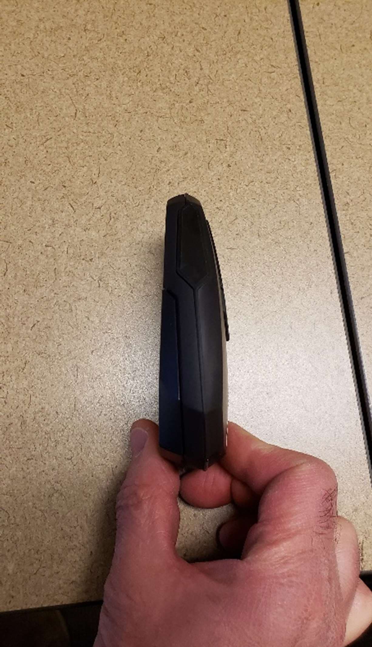
Click to zoom
Application Details
- Equipment Class
- DTS - Digital Transmission System
- Date of Grant
- Jul 12, 2021
- Application Purpose
- Original Equipment
- Date of Application
- Jul 12, 2021
- Equipment Note
- 2580
- Frequency Range
- 2402.00000000 - 2480.00000000
- Country
- United States
Documents & Files
Document Text
Text extracted from the exhibit documents filed with the FCC. Open a document above to read the original.
Users Manual
INSPIRE SLEEP REMOTE™ Rx Only Inspire Sleep Remote Model 2580 200-423-001_Rev A_2580 Manual US.book Page 1 The following is a registered trademark of Inspire Medical Systems, Inc.: Inspire® The following is a trademark of Inspire Medical Systems, Inc.: Inspire Sleep Remote™ 200-423-001_Rev A_2580 Manual US.book Page 2 Inspire Sleep RemoteEnglish i Explanation of Symbols on Sleep Remote or Package Turn therapy on button; or, if therapy is already on, then push to pause therapy Turn therapy off button Decrease stimulation strength button Increase stimulation strength button Replace sleep remote batteries status light Generator battery may be low status light Communication with your generator has been interrupted due to Electromagnetic Interference (EMI) status light Bluetooth® pairing is in process status light Stimulation strength is at the upper limit status light 200-423-001_Rev A_2580 Manual US.book Page i ii EnglishInspire Sleep Remote Consult instructions for use Reference number Serial number IEC 60601-1/EN60601-1, Type BF Equipment This symbol means that the device comes into contact with the patient Keep dry, use caution to prevent spilling or splashing liquids on the sleep remote Manufacturer Date of manufacture MRI unsafe Temperature limitation Atmospheric pressure limitation Relative humidity limitation IEC 60529, Protection from ingress by fingers or similar objects and moderate amounts of dripping water Note: The sleep remote meets the water ingress rating of IP22, maintaining safe operation. Exposure to water or liquids could result in a loss of performance. Keep the sleep remote dry. Refer to “Battery and Sleep Remote Disposal” on page40 for more detailed information. IP22 200-423-001_Rev A_2580 Manual US.book Page ii Inspire Sleep RemoteEnglish iii Inspire Sleep Remote TM Quick Guide Figure 1.Sleep remote front view Turning Therapy On • Press the Therapy On () button and hold the sleep remote over your generator for 10 seconds or until the sleep remote produces an audio tone. • When therapy is turned on, the generator will produce a brief stimulation pulse. Status Ring WhiteTherapy is off Green – SolidTherapy is on and stimulation is on Green – Dimming and brighteningTherapy is on, stimulation is paused Therapy On Therapy Off Increase (stimulation strength) Decrease (stimulation strength) Status ring Pause 200-423-001_Rev A_2580 Manual US.book Page iii iv EnglishInspire Sleep Remote Turning Therapy Off • Press the Therapy Off button () and hold the sleep remote over your generator for 10 seconds or until the sleep remote produces an audio tone. Note: Removing the batteries from your sleep remote will not turn off the therapy. Decreasing Stimulation Strength • Press the Decrease button () and hold the sleep remote over your generator for 10 seconds. When audio is enabled, the sleep remote will produce an audio tone when you decrease stimulation. • If the stimulation strength is at the lower limit when you press the Decrease button () and audio is enabled, the remote will immediately emit three beeps. Increasing Stimulation Strength • Press the Increase button () and hold the sleep remote over your generator for 10 seconds. When audio is enabled, the sleep remote will produce an audio tone when you increase stimulation. • If the stimulation strength is at the upper limit when you press the Increase button () and audio is enabled, the remote will immediately emit three beefs. Pausing Therapy • While therapy is on, press the Therapy On button () and hold the sleep remote over your generator for 10 seconds or until the sleep remote produces an audio tone. 200-423-001_Rev A_2580 Manual US.book Page iv Inspire Sleep RemoteEnglish v Figure 2.Sleep remote back view Status Indicators Replace sleep remote batteries If the light is on, your generator battery may be low or therapy disabled, call your doctor If the light is on and flashing, communication with your generator has been interrupted due to Electromagnetic Interference (EMI). Refer to “Interference” on page8. Stimulation strength is at the upper limit Stimulation strength gauge Bluetooth pairing is in process Sleep remote battery light Bluetooth EMI Upper limit light Stimulation strength gauge Generator light 200-423-001_Rev A_2580 Manual US.book Page v vi EnglishInspire Sleep Remote Finding the Generator • Press the Therapy Off button () and move the sleep remote near your generator. When the sleep remote produces two beeps, with the second beep at a higher tone than the first, you have found the generator location. • If the sleep remote produces three rapid beeps, you have not found the generator location. Try again. Audio Tones Two beeps with the second beep at a higher tone than the first • Communication with the generator was successful Three rapid beeps• Communication with the generator was not successful, try again • Stimulation is at the upper or lower limit Two beeps that repeat • Sleep remote is updating the generator • Wait until complete, when the success tone is played • Update may take several seconds 200-423-001_Rev A_2580 Manual US.book Page vi Inspire Sleep RemoteEnglish vii Table of Contents Explanation of Symbols on Product or Packagei Inspire Sleep Remote TM Quick Guideiii Glossaryix 1. Introduction1 About This Manual2 Package Contents2 2. Inspire Therapy3 Your Inspire System3 Therapy Summary4 Additional Therapy Information5 Frequently Asked Therapy Questions5 3. Safety Information7 Warnings7 Precautions8 System and Therapy8 Patient Activities8 Interference8 4. Using Your Sleep Remote11 Sleep Remote Buttons12 Status Ring13 Stimulation Strength Gauge14 Status Lights16 Bluetooth Pairing with a Mobile Phone18 Using Your Inspire Sleep Remote21 Positioning Your Sleep Remote21 200-423-001_Rev A_2580 Manual US.book Page vii viii EnglishInspire Sleep Remote Communicating with your Generator24 Turning Therapy On26 Turning Therapy Off27 Pausing Therapy28 Increasing Stimulation Strength29 Decreasing Stimulation Stren…
Text truncated - open the document above for the full version.
Cover Letter(s)
Inspire Medical Systems, Inc. 5500 Wayzata Blvd., Suite 1600, Golden Valley, MN 55416 844-OSA-HELP | InspireSleep.com 10 June 2021 Federal Communications Commission Authorization and Evaluation Division 7435 Oakland Mills Road Columbia, Maryland 21046 Re: FCC Application FCC ID: 2AGO22580 To whom it may concern, We, Inspire Medical Systems Inc., hereby apply for original certification of the radios included in the Model 2580 Patient Remote. The telemetry intentional radiator operates at 175kHz and is compliant to 47 CFR §15.209. The Bluetooth radio operates at 2.4GHz and is compliant to 47 CFR §15.247. Sincerely, Sr. Director Regulatory: Joel Aaberg Telephone Number: 763-205-7972 Email: [email protected]
Cover Letter(s)
Inspire Medical Systems, Inc. 5500 Wayzata Blvd., Suite 1600, Golden Valley, MN 55416 844-OSA-HELP | InspireSleep.com 10 June 2021 Federal Communications Commission Authorization and Evaluation Division 7435 Oakland Mills Road Columbia, Maryland 21046 Re: Request for confidentiality FCC ID: 2AGO22580 To whom it may concern, Pursuant to Sections 0.457(d) and 0.459 of the Commission’s Rules, Inspire Medical Systems, Inc. hereby requests long-term confidential treatment of information accompanying this application as outlined below: • Block Diagram • Operational Description • Schematics Inspire Medical Systems, Inc. also hereby requests short-term confidential treatment of information accompanying this application as outlined below for a period of 180 days: • User Manual • External Photos • Test Set-up Photographs • Internal Photos The above materials contain trade secrets and proprietary information not customarily released to the public. The public disclosure of these matters might be harmful to the Applicant and provide unjustified benefits to its competitors. The Applicant understands that pursuant to Rule 0.457(d)(1)(ii), disclosure of this Application and all accompanying materials will not be made before the date of the Grant for this Application. Yours sincerely, Name: Joel Aaberg Title: Senior Director of Regulatory Affairs
External Photos
Inspire Medical System Model 2580 External Photos
Internal Photos
Inspire Medical System Additional Model 2580 Internal Photos – 10MAY21
Internal Photos
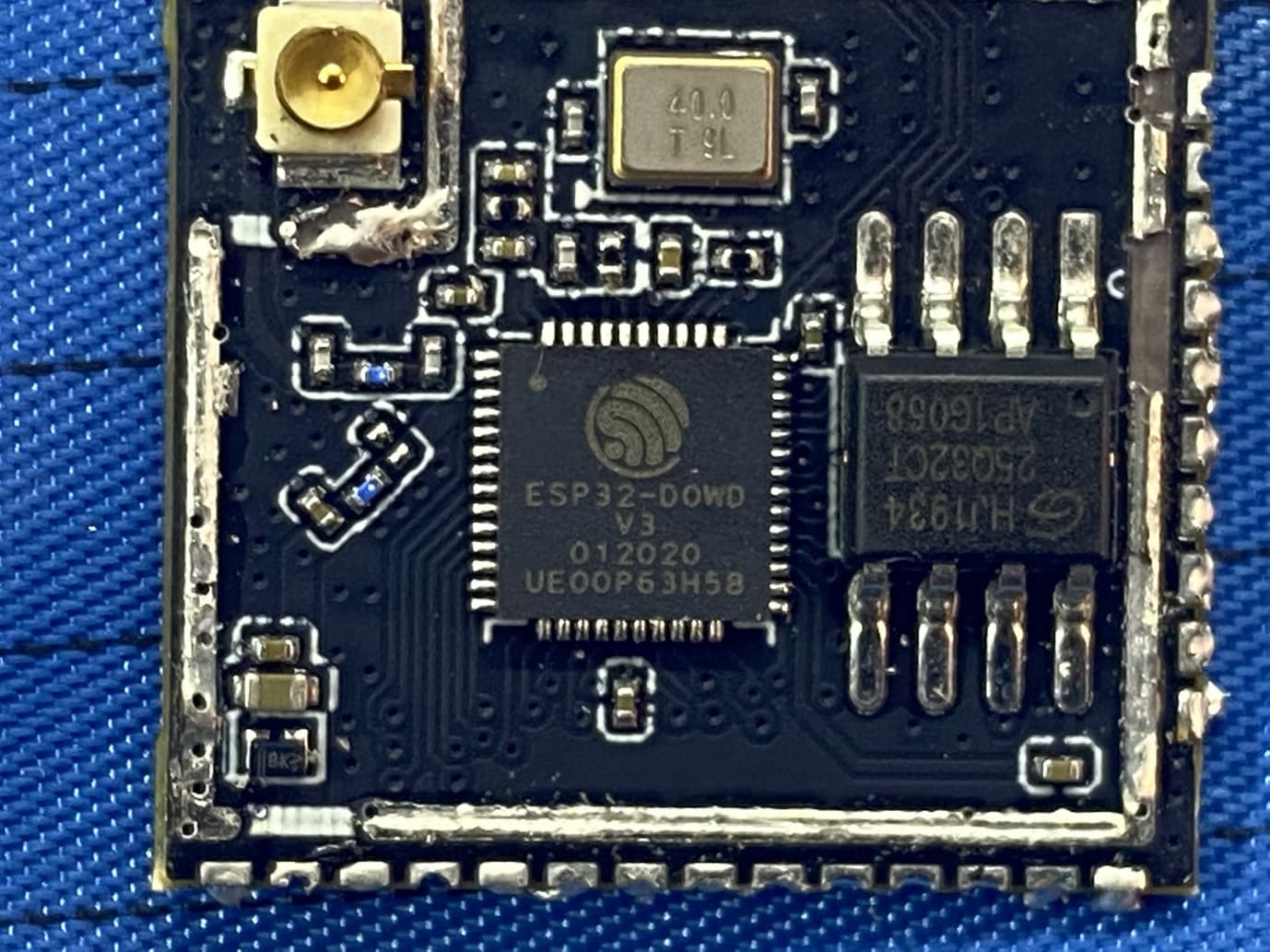
Inspire Medical System Model 2580 Internal Photos
Operational Description
1.800 1.920 200-398-000 Inspire Medical Systems, Inc. 1 .01 K. LARSON D C B A AB C D SIZE DWG NO. B SHEET OF REV. DATE DOCUMENT CREATED BY: 1 2 3 4 5 6 7 8 8 7 6 5 4 TITLE: 2 01 DATE Golden Valley, MN USA T. YOCH strictly prohibited. 3 1 X.XXX .005 COIL, MODEL 2580 ANGLES 9/22/2020 9/22/2020 1 2.0 APPROVED permission of Inspire is X.X .1 X.XX PROPERTY AND CONFIDENTIAL The information contained in this drawing is the sole property of Inspire. Any reproduction in part or as a whole without the express written All dimensions in inches unless otherwise noted OF SHIELD AS SHOWNMAGNET WIRE, GREEN, TIN BOTH ENDS, WRAP OUTSIDE SHIELD LEAD: 30GA END SHIELDING TAPE HERE SHIELDING TAPE: WRAP COIL HELICALLY WITH A SINGLE PIECE OF TAPE, LEAVING NO GAPS, WITH ENDPOINTS AS SHOWN. 2X .250KAPTON TAPE TOSECURE COIL 3X 1.30±.20 SECURE COIL 4X .375 KAPTON TAPE TO 3X .125 TIN ENDS HAVE ON ALL THE CHARACTERISTICS OF THE CTQ-5 (MAT'L CERTS) OF THE CHANGE AND THE EFFECT THE CHANGE WILL PROPOSED DEVICE/MATERIAL FOR EVALUATION AND APPROVAL BY INSPIRE MEDICAL SYSTEMS.MANUFACTURER SHALL SUBMIT SAMPLES OF THE DEVICE/MATERIAL. UPON REQUEST, THE CTQ-4 CTQ-6 CTQ-3 NOTES:1. MATERIALS: 34 0 TURNS 26GA LITZ WIRE (15 STRANDS OF 38GA HEAVY POLYURETHANE NYLON MW80-C), KAPTON TAPE, 3M 2191FR SHIELDING TAPE (NICKEL ON COPPER-PLATED POLYESTER FABRIC WITH CONDUCTIVE ACRYLIC ADHESIVE), 30GA MAGNET WIRE (SINGLE POLYURETHANE NYLON MW80-C,GREEN). MATERIAL CERTIFICATION TO BE PROVIDED WITH EACH LOT.2. COIL INDUCTANCE SHALL BE 111 3 uH AT 175kHz 10% (TO BE TESTED AT VENDOR) 3 CONTINUITY BETWEEN DRAIN AND EXPOSED SHIELD SHALL BE VERIFIED BY VENDOR.4. SEE CAD MODEL FOR COMPLETE DEFINITION OF COIL CENTERLINE GEOMETRY.5. CTQ ARE CRITICAL INSPECTION DIMENSIONS (6).6. THE PARTS SHALL BE PACKAGED IN A MANNER THAT PREVENTS DAMAGE OR CONTAMINATION FROM FOREIGN MATERIAL. EACH MANUFACTURING LOT SHALL BE LABELED IN ACCORDANCE WITH INSPIRE SPEC 700-006-000.7. UPON APPROVAL BY INSPIRE MEDICAL SYSTEMS OF THE INITIAL DESIGN, ANY PROCESS CHANGES, DESIGN CHANGES, PACKAGING CHANGES, RAW MATERIAL CHANGES, OR DEVIATIONS CONSIDERED BY THE MANUFACTURER MUST BE SUBMITTED TO INSPIRE IN WRITNG FOR PRE-APPROVAL. THE INFORMATION SUBMITTED SHALL INCLUDE A COMPLETE DESCRIPTION CTQ-1 CTQ-2 3 WRAP COIL HELICALLY WITH KAPTON TAPE, OVER SHIELD, WITH MINIMUM OVERLAP. .10 .200 FINAL.125 34 TURNS OF26GA LITZ WIRE REV DESCRIPTION ECO NUMBER DATE DRFT APRV 01 INITIAL RELEASE 20-00720 9/22/2020 TY KL REVISION IMS P/N REV DESCRIPTION 200-398-001 01 COIL, MODEL 2580
Operational Description
SPE-11-8-146/M/SS Page 1 of 17 SPECIFICATION Part No. WLA.01 Model 2.4GHz High Efficiency Loop Antenna Description 2.5dBi 2400MHz to 2500MHz WLAN/WIFI/Bluetooth/Zigbee Features 3.2*1.6*0.5mm Low Profile Peak gain 2.5dBi 50 Ohm Impedance RoHS Compliant SPE-11-8-146/M/SS Page 2 of 17 1. Introduction The WLA.01 2.4GHz Loop antenna is a high efficiency, miniature SMD, edge mounted ceramic antenna for very small space requirements for Wi-Fi, WLAN, Zigbee, Bluetooth, and 802.11 applications. The WLA.01 uses the main PCB as its ground plane, thereby increasing Antenna Efficiency. It is tuned for different PCB sizes by simply changing the value of the matching circuit. At 3.2mm*1.6mm*0.5mm, the WLA.01 is one of the smallest antennas available worldwide. This antenna is delivered on tape and Reel. Many module manufacturers specify peak gain limits for any antennas that are to be connected to that module. Those peak gain limits are based on free-space conditions. In practice, the peak gain of an antenna tested in free-space can degrade by at least 1 or 2dBi when put inside a device. So ideally you should go for a slightly higher peak gain antenna than mentioned on the module specification to compensate for this effect, giving you better performance. Upon testing of any of our antennas with your device and a selection of appropriate layout, integration technique, or cable, Taoglas can make sure any of our antennas’ peak gain will be below the peak gain limits. Taoglas can then issue a specification and/or report for the selected antenna in your device that will clearly show it complying with the peak gain limits, so you can be assured you are meeting regulatory requirements for that module. For example, a module manufacturer may state that the antenna must have less than 2dBi peak gain, but you don’t need to select an embedded antenna that has a peak gain of less than 2dBi in free-space. This will give you a less optimized solution. It is better to go for a slightly higher free-space peak gain of 3dBi or more if available. Once that antenna gets integrated into your device, performance will degrade below this 2dBi peak gain due to the effects of GND plane, surrounding components, and device housing. If you want to be absolutely sure, contact Taoglas and we will test. Choosing a Taoglas antenna with a higher peak gain than what is specified by the module manufacturer and enlisting our help will ensure you are getting the best performance possible without exceeding the peak gain limits. 1.1 Applications • Bluetooth earphone systems • Hand-held devices when Bluetooth/Wi-Fi functions are needed, e.g., Smart phone. • IEEE802.11 b/g • ZigBee • Wireless PCMCIA cards or USB dongle SPE-11-8-146/M/SS Page 3 of 17 2. Specifications The WLA.01 is designed to mount at the center of the edge of an evaluation board of 80 x 40mm.The antenna performance was measured with the WLA.01 mounted on the evaluation board with SMA(F) connector. No Parameter Specification* 1 Center Frequency 2400-2500MHz 2 Dimensions 3.2*1.6*0.5mm 3 VSWR 2 max 4 Polarization Linear 5 Bandwidth 100MHz min. 6 Gain Peak 2.5dBi typ. 7 Efficiency 84% typ. 8 Impedance 50 W Mechanical 9 Dimensions 3.2*1.6*0.5mm 10 Material Ceramic Environmental 11 Operating Temperature -40°C~+85°C 12 Storage Temperature -40°C~+105°C 13 Temperature Coefficient(τf) 0 ± 20 ppm @-20ºC to +80ºC 14 Recommended Reel Storage Condition 5°C to 40°C Relative Humidity 20% to 70% * The data was measured by a CTIA Authorized Test Lab. ** Center frequency will be offset to working frequency according to the conditions of user’s Ground plane and radome. SPE-11-8-146/M/SS Page 4 of 17 3. Electrical Specification (80*40mm ground plane) 3.1 Return Loss(S11) SPE-11-8-146/M/SS Page 5 of 17 3.2 VSWR SPE-11-8-146/M/SS Page 6 of 17 4. Radiation Pattern (Customize Design) 4.1 Radiation Pattern (80mmX40mm ground plane) X Z Y SPE-11-8-146/M/SS Page 7 of 17 4.2 3D Gain pattern @2442MHz SPE-11-8-146/M/SS Page 8 of 17 4.3 Efficiency Table SPE-11-8-146/M/SS Page 9 of 17 4.4 Efficiency vs Frequency SPE-11-8-146/M/SS Page 10 of 17 5. Layout Guide 5.1 Solder Land Pattern Land pattern for soldering (grey marking areas) is as shown below. A matching circuit similar to the one shown in section 5.3 is also required. SPE-11-8-146/M/SS Page 11 of 17 5.2 Solder Land Pattern This antenna includes a fine tuning element (as shown in the land patterns above) that can be used to slightly shift antenna resonance. 5.3 Matching Circuit Like all antennas, surrounding components, enclosures, and changes to the GND plane dimensions can alter performance. A pi-matching network like the one shown below is required in case adjustments need to be made. The antenna EVB has a similar matching network. The components on the EVB are a good starting point for a new design, but will need to be adjusted upon integration for best performance. The zero ohm resistor is needed for the ability to solder down a coax pigtail to make measurements with a vector network analyzer. SPE-11-8-146/M/SS Page 12 of 17 6. Antenna Drawings 6.1 Antenna Main Body 6.2 Antenna with EVB SPE-11-8-146/M/SS Page 13 of 17 6.3 Footprint on EVB SPE-11-8-146/M/SS Page 14 of 17 7. Packaging 6000pcs WLA.01 per Carton Dimensions: 340*340*90mm Weight:3.5Kg 6000pcs WLA.01 per Tape and Reel Dimensions: Ø330*60mm Weight: 3.23Kg 47mm 60mm 9 0mm Ø 3 3 0mm 340mm 340mm SPE-11-8-146/M/SS Page 15 of 17 7.1 Tape Dimensions (unit: mm) 7.2 Pocket Dimensions (unit: mm) Feature Specifications Tolerances W 12 ±0.30 P 8 ±0.10 E 1.75 ±0.10 F 5.5 ±0.10 P2 2 ±0.10 D 1.5 ±0.10 Po 4 ±0.10 10Po 40 ±0.20 Feature Specifications Tolerances Ao 1.9 ±0.10 Bo 3.5 ±0.10 Ko 0.8 ±0.10 t 0.3 ±0.05 SPE-11-8-146/M/SS Page 16 of 17 8. Recommended Reflow Temp Profile The WLA.01 Loop Antenna can be assembled following either Sn-Pb or Pb-Free assembly processes. The recommended soldering temperatures are as follows: SPE-11-8-146/M/SS Page 17 of 17 Ta o g l a s m a k e s n o wa r ra n t i e s b a s e…
Text truncated - open the document above for the full version.
RF Exposure Info
This report must not be used to claim product certification, approval, or endorsement by NVLAP, NIST, or any agency of the U.S. Government. This Report shall not be reproduced, except in full without written approval of the laboratory. EAR-Controlled Data - This document contains technical data whose export and reexport/retransfer is subject to control by the U.S. Department of Commerce under the Export Administration Act and the Export Administration Regulations. The Department of Commerce’s prior written approval may be required for the export or re- export/retransfer of such technical data to any foreign person, foreign entity or foreign organization whether in the United States or abroad. More: https://www.bis.doc.gov/index.php/forms-documents/regulations-docs/14-commerce-country-chart/fileT Inspire Medical Systems Inspire Remote Model 2580 FCC 2.1093:2021 Bluetooth LE Radio Inductive Radio Report: INSP0027.8, Issue Date: June 2, 2021 NVLAP LAB CODE: 200630-0 CERTIFICATE OF EVALUATION 2018-09-14 Product compliance is the responsibility of the client; therefore, the tests and equipment modes of operation represented in this report were agreed upon by the client, prior to testing. The results of this test pertain only to the sample(s) tested. The specific description is noted in each of the individual sections of the test report supporting this certificate of test. This report reflects only those tests from the referenced standards shown in the certificate of test. It does not include inspection or verification of labels, identification, marking or user information. As indicated in the Statement of Work sent with the quotation, Element’s standard process is to always use the latest published version of the test methods even when earlier versions are cited in the test specification. Issuance of a purchase order was de facto acceptance of this approach. Otherwise, the client would have advised Element in writing of the specific version of the test methods they wanted applied to the subject testing Last Date of Evaluation: Friday, May 21, 2021 Inspire Medical Systems EUT: Inspire Remote Model 2580 RF Exposure Evaluation Standards Specification Method FCC 2.1093:2021 FCC 1.1307:2021 FCC 680106 D01 RF Exposure Wireless Charging Apps v03r01 Results Method Clause Description Applied Results Comments (b)(3)(ii)(B) RF Exposure Exemption for Multiple RF Sources Yes Pass None Deviations From Evaluation Standards None Approved By: Donald Facteau, Process Architect Report No. INSP0027.8EAR-Controlled Data2/19 REVISION HISTORY 2018.07.17 Revision Number Description Date (yyyy-mm-dd) Page Number 00 None Report No. INSP0027.8EAR-Controlled Data3/19 ACCREDITATIONS AND AUTHORIZATIONS 2021.02.26 United States FCC - Designated by the FCC as a Telecommunications Certification Body (TCB). Certification chambers, Open Area Test Sites, and conducted measurement facilities are listed with the FCC. A2LA - Accredited by A2LA to ISO / IEC 17065 as a product certifier. This allows Element to certify transmitters to FCC and IC specifications. NVLAP - Each laboratory is accredited by NVLAP to ISO 17025 Canada ISED - Recognized by Innovation, Science and Economic Development Canada as a Certification Body (CB) and as a CAB for the acceptance of test data. European Union European Commission – Recognized as an EU Notified Body validated for the EMCD and RED Directives. United Kingdom BEIS – Recognized by the UK as an Approved Body under the UK Radio Equipment and UK EMC Regulations. Australia/New Zealand ACMA - Recognized by ACMA as a CAB for the acceptance of test data. Korea MSIT / RRA - Recognized by KCC’s RRA as a CAB for the acceptance of test data. Japan VCCI - Associate Member of the VCCI. Conducted and radiated measurement facilities are registered. Taiwan BSMI – Recognized by BSMI as a CAB for the acceptance of test data. NCC - Recognized by NCC as a CAB for the acceptance of test data. Singapore IDA – Recognized by IDA as a CAB for the acceptance of test data. Israel MOC – Recognized by MOC as a CAB for the acceptance of test data. Hong Kong OFCA – Recognized by OFCA as a CAB for the acceptance of test data. Vietnam MIC – Recognized by MIC as a CAB for the acceptance of test data. SCOPE For details on the Scopes of our Accreditations, please visit: https://www.nwemc.com/emc-testing-accreditations Report No. INSP0027.8EAR-Controlled Data4/19 FACILITIES 2020.12.15 California Labs OC01-17 41 Tesla Irvine, CA 92618 (949) 861-8918 Minnesota Labs MN01-11 9349 W Broadway Ave. Brooklyn Park, MN 55445 (612)-638-5136 Oregon Labs EV01-12 6775 NE Evergreen Pkwy #400 Hillsboro, OR 97124 (503) 844-4066 Texas Labs TX01-09 3801 E Plano Pkwy Plano, TX 75074 (469) 304-5255 Washington Labs NC01-05 19201 120 th Ave NE Bothell, WA 98011 (425)984-6600 NVLAP NVLAP Lab Code: 200676-0 NVLAP Lab Code: 200881-0 NVLAP Lab Code: 200630-0 NVLAP Lab Code:201049-0 NVLAP Lab Code: 200629-0 Innovation, Science and Economic Development Canada 2834B-1, 2834B-3 2834E-1, 2834E-3 2834D-1 2834G-1 2834F-1 BSMI SL2-IN-E-1154R SL2-IN-E-1152R SL2-IN-E-1017 SL2-IN-E-1158R SL2-IN-E-1153R VCCI A-0029 A-0109 A-0108 A-0201 A-0110 Recognized Phase I CAB for ISED, ACMA, BSMI, IDA, KCC/RRA, MIC, MOC, NCC, OFCA US0158 US0175 US0017 US0191 US0157 Report No. INSP0027.8EAR-Controlled Data5/19 PRODUCT DESCRIPTION 2018-07-17 Client and Equipment Under Evaluation Information Company Name: Inspire Medical Systems Address: 5500 Wayzata Blvd., Suite 1600 City, State, Zip: Golden Valley, 55416 Evaluation Requested By: Charles Steaderman EUT: Inspire Remote Model 2580 Date of Evaluation: Friday, May 21, 2021 Information Provided by the Party Requesting the Evaluation Functional Description of the Equipment: The Inspire Model 2580 Patient Remote is a battery-powered (two AA) handheld "Remote" device used to start/stop/configure sleep apnea therapy sessions of an implantable device (in the upper chest area of a patient). The Remote is intended for in-home use by a patient. …
Text truncated - open the document above for the full version.
Test Report
This report must not be used to claim product certification, approval, or endorsement by NVLAP, NIST, or any agency of the U.S. Government. This Report shall not be reproduced, except in full without written approval of the laboratory. Inspire Medical Systems Inspire Remote Model 2580 FCC 15.247:2021 Bluetooth LE Radio Report: INSP0027, Issue Date: May 26, 2021 NVLAP LAB CODE: 200881-0 CERTIFICATE OF TEST 2018-09-14 Product compliance is the responsibility of the client; therefore, the tests and equipment modes of operation represented in this report were agreed upon by the client, prior to testing. The results of this test pertain only to the sample(s) tested. The specific description is noted in each of the individual sections of the test report supporting this certificate of test. This report reflects only those tests from the referenced standards shown in the certificate of test. It does not include inspection or verification of labels, identification, marking or user information. As indicated in the Statement of Work sent with the quotation, Element’s standard process is to always use the latest published version of the test methods even when earlier versions are cited in the test specification. Issuance of a purchase order was de facto acceptance of this approach. Otherwise, the client would have advised Element in writing of the specific version of the test methods they wanted applied to the subject testing. Last Date of Test: May 20, 2021 Inspire Medical Systems EUT: Inspire Remote Model 2580 Radio Equipment Testing Standards Specification Method FCC 15.247:2021 ANSI C63.10:2013, KDB 558074 Results Method Clause Test Description Applied Results Comments 6.2 Powerline Conducted Emissions No N/A Not required for a battery powered EUT. 6.5, 6.6, 11.12.1, 11.13.2 Spurious Radiated Emissions Yes Pass 11.6 Duty Cycle Yes Pass 11.8.2 Occupied Bandwidth Yes Pass 11.9.1.1 Output Power Yes Pass 11.9.1.1 Equivalent Isotropic Radiated Power Yes Pass 11.10.2 Power Spectral Density Yes Pass 11.11 Band Edge Compliance Yes Pass 11.11 Spurious Conducted Emissions Yes Pass Deviations From Test Standards None Approved By: Eric Brandon, Department Manager Report No. INSP00272/59 REVISION HISTORY 2018.07.17 Revision Number Description Date (yyyy-mm-dd) Page Number 00 None Report No. INSP00273/59 ACCREDITATIONS AND AUTHORIZATIONS 2021.02.26 United States FCC - Designated by the FCC as a Telecommunications Certification Body (TCB). Certification chambers, Open Area Test Sites, and conducted measurement facilities are listed with the FCC. A2LA - Accredited by A2LA to ISO / IEC 17065 as a product certifier. This allows Element to certify transmitters to FCC and IC specifications. NVLAP - Each laboratory is accredited by NVLAP to ISO 17025 Canada ISED - Recognized by Innovation, Science and Economic Development Canada as a Certification Body (CB) and as a CAB for the acceptance of test data. European Union European Commission – Recognized as an EU Notified Body validated for the EMCD and RED Directives. United Kingdom BEIS – Recognized by the UK as an Approved Body under the UK Radio Equipment and UK EMC Regulations. Australia/New Zealand ACMA - Recognized by ACMA as a CAB for the acceptance of test data. Korea MSIT / RRA - Recognized by KCC’s RRA as a CAB for the acceptance of test data. Japan VCCI - Associate Member of the VCCI. Conducted and radiated measurement facilities are registered. Taiwan BSMI – Recognized by BSMI as a CAB for the acceptance of test data. NCC - Recognized by NCC as a CAB for the acceptance of test data. Singapore IDA – Recognized by IDA as a CAB for the acceptance of test data. Israel MOC – Recognized by MOC as a CAB for the acceptance of test data. Hong Kong OFCA – Recognized by OFCA as a CAB for the acceptance of test data. Vietnam MIC – Recognized by MIC as a CAB for the acceptance of test data. SCOPE For details on the Scopes of our Accreditations, please visit: https://www.nwemc.com/emc-testing-accreditations Report No. INSP00274/59 FACILITIES 2020.12.15 California Labs OC01-17 41 Tesla Irvine, CA 92618 (949) 861-8918 Minnesota Labs MN01-11 9349 W Broadway Ave. Brooklyn Park, MN 55445 (612)-638-5136 Oregon Labs EV01-12 6775 NE Evergreen Pkwy #400 Hillsboro, OR 97124 (503) 844-4066 Texas Labs TX01-09 3801 E Plano Pkwy Plano, TX 75074 (469) 304-5255 Washington Labs NC01-05 19201 120 th Ave NE Bothell, WA 98011 (425)984-6600 NVLAP NVLAP Lab Code: 200676-0 NVLAP Lab Code: 200881-0 NVLAP Lab Code: 200630-0 NVLAP Lab Code:201049-0 NVLAP Lab Code: 200629-0 Innovation, Science and Economic Development Canada 2834B-1, 2834B-3 2834E-1, 2834E-3 2834D-1 2834G-1 2834F-1 BSMI SL2-IN-E-1154R SL2-IN-E-1152R SL2-IN-E-1017 SL2-IN-E-1158R SL2-IN-E-1153R VCCI A-0029 A-0109 A-0108 A-0201 A-0110 Recognized Phase I CAB for ISED, ACMA, BSMI, IDA, KCC/RRA, MIC, MOC, NCC, OFCA US0158 US0175 US0017 US0191 US0157 Report No. INSP00275/59 MEASUREMENT UNCERTAINTY TMU.2015.07.10 Measurement Uncertainty When a measurement is made, the result will be different from the true or theoretically correct value. The difference is the result of tolerances in the measurement system that cannot be completely eliminated. To the extent that technology allows us, it has been our aim to minimize this error. Measurement uncertainty is a statistical expression of measurement error qualified by a probability distribution. A measurement uncertainty estimation has been performed for each test per our internal quality document QM205.4.6. The estimation is used to compare the measured result with its "true" or theoretically correct value. The expanded measurement uncertainty (K=2) can be found in the table below. A lab specific value may also be found in the applicable test description section. Our measurement data meets or exceeds the measurement uncertainty requirements of the applicable specification; therefore, the test data can be compared directly to the specification limit to determine compliance. The calculations for es…
Text truncated - open the document above for the full version.
Test Setup Photos
RADIATED TESTING photo PSA-ESCI 2021.01.22.0 photos PSA-ESCI 2021.01.22.0 SE BELOW 30 001.jpg SE BELOW 30 002.jpg BELOW 30 002 RADIATED TESTING photo PSA-ESCI 2021.01.22.0 photos PSA-ESCI 2021.01.22.0 SE BELOW 30 003.jpg
Test Setup Photos
XMit 2020.12.30.0 MN09 BENCH 001.jpg MN09 BENCH 002.jpg DIRECT CONNECT photo PSA-ESCI 2021.01.22.0 photos PSA-ESCI 2021.01.22.0 SRE (1).JPG SRE (2).JPG -2 SPURIOUS RADIATED EMISSIONS photo PSA-ESCI 2021.01.22.0 photos PSA-ESCI 2021.01.22.0 SRE (3).JPG SRE (4).JPG -4 SPURIOUS RADIATED EMISSIONS photo PSA-ESCI 2021.01.22.0 photos PSA-ESCI 2021.01.22.0 SRE (5).JPG SPURIOUS RADIATED EMISSIONS
Contact Information
Applicant
Dave Dieken(Program Director)
Test Firm
Element Materials Technology MinneapolisRenee Walker
Technical Specifications
| # | Rule Parts | Frequency Range | Power Output |
|---|---|---|---|
| 1 | 15C | 2.40 GHz - 2.48 GHz | 3.00 mW |
Other Applications from Inspire Medical Systems, Inc.
2AGO22740PGC
Feb 09, 20212740
Equipment Class
DTS - Digital Transmission System