2AGO22740PGC2740
Inspire Medical Systems, Inc.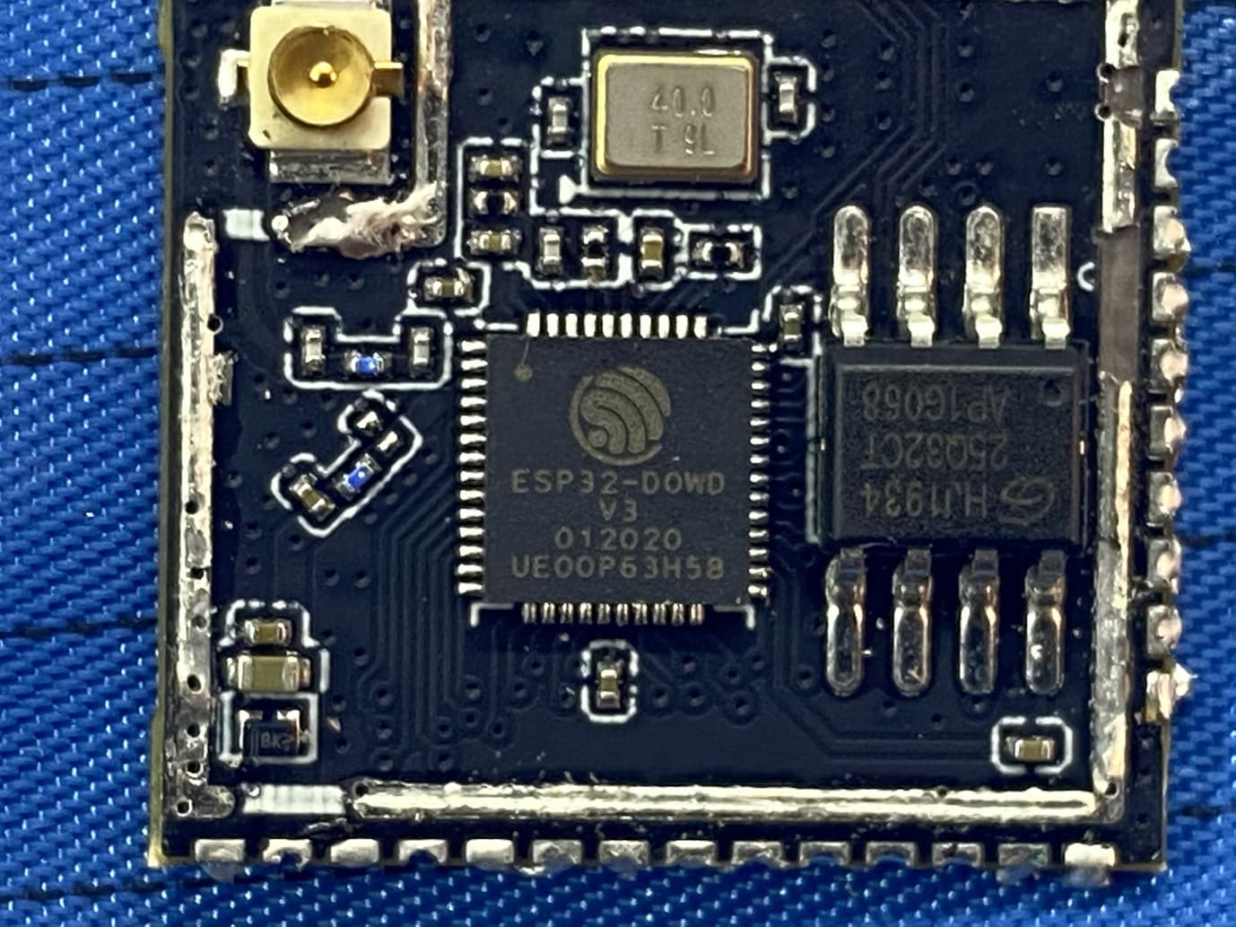
Click to zoom
Application Details
- Equipment Class
- DTS - Digital Transmission System
- Date of Grant
- Feb 09, 2021
- Application Purpose
- Original Equipment
- Date of Application
- Feb 08, 2021
- Equipment Note
- 2740
- Frequency Range
- 2402.00000000 - 2480.00000000
- Country
- United States
Documents & Files
Document Text
Text extracted from the exhibit documents filed with the FCC. Open a document above to read the original.
Users Manual
PROGRAMMER MANUAL Programmer Model 2740 ONLY The following is a trademark of Inspire Medical Systems, Inc.: Inspire® This product and/or the use of this product in a method may be covered by one or more patents or patent applications, available at www.inspiresleep.com/patents. Programmer Model 2740English i TABLE OF CONTENTS Explanation of Symbols iii Explanation of Symbols on Package Labeling and Device iii How to Use this Guide ix Chapter 1: Therapy Overview 1 Introduction 1 Terminology 2 Therapy Icons 7 Chapter 2: Programmer Components 9 Package Contents 9 Chapter 3: Getting Started 17 Turning On the Programmer 17 Starting a Session 20 Exiting a Session and Turning Off the Programmer 29 Chapter 4: Screen Descriptions 31 Common Screen Elements 31 Start Screen 34 Programmer Settings Screen 35 Home Screen 36 Patient Details Screen 41 Adjust Stimulation Screen 43 Adjust Sensing Screen 49 Select a Patient Screen 53 Reports Screen 55 Stimulation History Screen 59 Sensing History Screen 60 Chapter 5: Clinical Programming Sessions 61 Introduction 61 When To Use Workflows 61 Generator Implant 61 Initial Activation 67 Follow Up 70 Sleep Study 76 Exporting a Report 81 Chapter 6: Troubleshooting 83 Communications 83 Tablet 84 ii EnglishProgrammer Model 2740 Programmer Cable - Error Mode 85 Settings 85 Therapy 86 Waveforms 88 Reports 88 Abnormal Impedances 88 Generator Reset 89 Exporting 89 Chapter 7: Warnings and Precautions 91 Warnings 91 Precautions 91 Chapter 8: Supplemental Information 95 Programmer Maintenance 95 Default Settings 96 Device Specifications 97 Protected Health Information 99 Introduction 99 Essential Performance 99 FCC Notice (USA) 99 Electromagnetic Compatibility Declarations 101 Unused Tablet Features 107 Disposing of Programmer 110 Chapter 9: Inspire Medical Systems, Inc. Limited Warranty 111 Inspire Medical Systems, Inc. Limited Warranty 111 Programmer Model 2740English iii Explanation of Symbols Explanation of Symbols on Package Labeling and Device Refer to the package label and device labels to see which symbols apply. SymbolDescription Caution, consult accompanying documents Consult electronic instructions for use (eIFU) Consult instructions for use Nonsterile Fragile Keep dry Serial number iv EnglishProgrammer Model 2740 Temperature limitation Atmospheric pressure limitation Relative humidity limitation Federal Communications Commission notice (USA) For US audiences only Manufacturer Product complies with 2002/96/EC Non-ionizing electromagnetic radiation SymbolDescription Programmer Model 2740English v Conformité Européenne (European Conformity). This symbol means that the device fully complies with European Directive 90/385/EEC. Conformité Européenne; compliance to EMC Directive and Low Voltage Directive of the European Union. European authorized representative Compliance with Underwriters Laboratories for general product safety in accordance with UL 60950-1 (ITE) and CAN/CSA C22.2 No. 60950-1 (ITE) Power button Type BF Applied part protection against electrical shock Output connector polarity Class II double insulated SymbolDescription 2797 vi EnglishProgrammer Model 2740 CEC Level V compliant UL recognized component mark IECEE CB compliant Indoor use only TUV/T-Mark for IEC/EN 60601-1 Compliance Degree of ingress protection per EN60529 Degree of ingress protection per EN60529 The Inspire Programmer is MR unsafe SymbolDescription Programmer Model 2740English vii The Technical Conformity mark signifies that this device complies with Japan Radio Law The Regulatory Compliance Mark (RCM) signifies that this device complies with Australian Communications and Media Authority requirements SymbolDescription viii EnglishProgrammer Model 2740 Programmer Model 2740English ix How to Use this Guide This guide presents information for users of the Inspire Programmer (Model 2740) for programming an Inspire Generator. The chapters are organized as follows: •Therapy Overview This chapter is a brief overview of Inspire therapy and its indications along with programmer terminology and icons. • Programmer Components This chapter describes the programmer tablet, programmer cable, and accessories. • Getting Started This chapter provides instructions on how to set up and start the programmer and how to start and end a programming session. • Screen Descriptions This chapter provides detailed descriptions of the programmer screens. • Clinical Programming Sessions This chapter provides instructions for programming procedures (workflows) at implant, initial activation, follow up, and sleep studies. • Troubleshooting This chapter contains solutions to problems that may be encountered during programmer use. •Warnings and Precautions This chapter provides programmer warnings and precautions. •Supplemental Information This chapter provides general reference information, such as device specifications and proper procedures for cleaning, servicing, and maintaining the programmer. This chapter also includes HIPPA and regulatory information. • Limited Warranty This chapter describes the device limited warranty. This warranty applies only in the United States. Areas outside the United States should contact an Inspire Medical Systems representative for exact warranty terms. x EnglishProgrammer Model 2740 Programmer Model 2740English 1 Chapter 1: Therapy Overview This chapter is a brief overview of the Inspire system technology and icons. Introduction The Inspire® Upper Airway Stimulation (UAS) system (Figure1-1) stimulates the hypoglossal nerve, synchronous with respiration, to elicit a neuromuscular response at the base of the tongue and to maintain airway patency in patients with moderate to severe obstructive sleep apnea (OSA). The implanted components of the Inspire system consist of an Inspire Generator, the Inspire Stimulation Lead, and the Inspire Respiration Sensing Lead. The implanted system is programmed using the Inspire programmer. The patient uses a patient remote to turn therapy on and off a…
Text truncated - open the document above for the full version.
External Photos
(Controller Back) (Controller Bottom) (Controller Front) (Controller Left) (Controller Right) (Controller Top) (Head Back) (Head Bottom) (Head Front) (Head Left) (Head Right) (Head Top) (PGC System) Scale External Photos System and Accessories
External Photos
EXHIBIT B - EUT INTERNAL PHOTOGRAPHS
ID Label/Location Info
Inspire Medical Systems, Inc. 11/25/2019 permission of Inspire is D C B AA B C D SIZE DWG NO. B SHEET OF REV. DATEDOCUMENT CREATED BY: 12 3 45 6 7 8 8 7 6 5 4 3 .01 DATEAPPROVED 11/25/2019 1 Golden Valley, MN USA ANGLES A. RASMUSSEN B200-334-000 strictly prohibited. X.XXX PROGRAMMER CABLE .005 1 TITLE: BACK LABEL, 2 2.0 T. YOCH 1 X.X .1 X.XX PROPERTY AND CONFIDENTIAL The information contained in this drawing is the sole property of Inspire. Any reproduction in part or as a whole without the express written All dimensions in inches unless otherwise noted 3.308±.015 .012 CTQ-2 CTQ-1 NOTES: 1. MATERIAL: 10 MIL MARNOT XL HARDCOATED CLEAR GLOSS PC WITH 3M 7952MP REAR ADHESIVE (2 MIL). MATERIAL CERTIFICATION TO BE PROVIDED WITH EACH LOT. 2. SEE ART FILES FOR COMPLETE GEOMETRY DEFINITION. P/N'S 200-334-001 & 200-334-002 HAVE THE SAME GEOMETRY WITH DIFFERENT ART AND SHARE THIS DRAWING (200-334-002 SHOWN). 3. CTQ ARE CRITICAL INSPECTION DIMENSIONS (2). 4. UNLESS OTHERWISE SPECIFIED GENERAL TOLERANCES APPLY: CUT-TO-CUT & PRINT-TO- CUT .020, PRINT TO PRINT .010. 5. THE PARTS SHALL BE PACKAGED IN A MANNER THAT PREVENTS DAMAGE OR CONTAMINATION FROM FOREIGN MATERIAL. EACH MANUFACTURING LOT SHALL BE LABELED IN ACCORDANCE WITH INSPIRE SPEC 700-006-000. 6. UPON APPROVAL BY INSPIRE MEDICAL SYSTEMS OF THE INITIAL DESIGN, ANY PROCESS CHANGES, DESIGN CHANGES, PACKAGING CHANGES, RAW MATERIAL CHANGES, OR DEVIATIONS CONSIDERED BY THE MANUFACTURER MUST BE SUBMITTED TO INSPIRE IN WRITNG FOR PRE-APPROVAL. THE INFORMATION SUBMITTED SHALL INCLUDE A COMPLETE DESCRIPTION OF THE CHANGE AND THE EFFECT THE CHANGE WILL HAVE ON ALL THE CHARACTERISTICS OF THE DEVICE/MATERIAL. UPON REQUEST, THE MANUFACTURER SHALL SUBMIT SAMPLES OF THE PROPOSED DEVICE/MATERIAL FOR EVALUATION AND APPROVAL BY INSPIRE MEDICAL SYSTEMS. .015 38,45,51) (UN7994, RGB: GRAPHITE ALL EXCEPT TOP PRINT, WHITE UV MATTE WINDOW WINDOW PRINT TO CUT TOLERANCE +/-.010 1.439 SELECTIVE REAR ADHESIVE REVDESCRIPTIONECO NUMBER DATEDRFTAPRV A INITIAL PRODUCTION RELEASE20-006757/17/2020TYKV B UPDATE FCC LABEL CONTENT21-007551/15/2021TYAR REVISION IMS P/N REV DESCRIPTION 200-334-001 B BACK LABEL, PROGRAMMER CABLE, US 200-334-002 B BACK LABEL, PROGRAMMER CABLE, GLOBAL
Internal Photos
EXHIBIT B - EUT INTERNAL PHOTOGRAPHS
Operational Description
permission of Inspire is D C B A AB C D SIZE DWG NO. B SHEET OF REV. DATE DOCUMENT CREATED BY: 1 2 3 4 5 6 7 8 8 7 6 5 4 32 1 B TITLE: T. YOCH CABLE HEAD 200-331-000 PCBA, PROGRAMMER Golden Valley, MN USAInspire Medical Systems, Inc. 12/2/2019 .01 K. LARSON 12/2/2019 X.XXX DATE APPROVED strictly prohibited. .005 1 1 2.0 ANGLESX.X .1 X.XX PROPERTY AND CONFIDENTIAL The information contained in this drawing is the sole property of Inspire. Any reproduction in part or as a whole without the express written All dimensions in inches unless otherwise noted 2% AT 100 kHz. 247.4 uH 5. CTQ ARE CRITICAL INSPECTION DIMENSIONS (1). AND TP2 WITH A CALIBRATED LCR METER, SHALL BE NOTES:1. THIS DRAWING IS INTENDED AS A MEANS OF COMMUNICATING LOCATIONS, SIZES, AND TOLERANCES OF MECHANICALLY RELEVANT FEATURES AND COMPONENTS. SEE LAYOUT FILES FOR COMPLETE MANUFACTURING INFORMATION.2. SEE PROVIDED DXF FILE FOR COMPLETE 2D GEOMETRY DEFINITION.3. PCB SHALL BE UL 94V-0 COMPLIANT AND MARKED AS SUCH.4. COIL INDUCTANCE, AS MEASURED BETWEEN TP1 CTQ-1 INDICATOR LABELKEEPOUT FOR (OR EQUIVALENT) JST SM10B-SURS-TF(LF)(SN) (OR EQUIVALENT) WURTH 150060YS55040 2X YELLOW LED, (OR EQUIVALENT) WURTH 150060BS55040 6X BLUE LED, .008 .004 3.150 .067±.003 THRU ALL 2X 75 2.953 COIL DIA .0272 4.075 REV DESCRIPTION ECO NUMBER DATE DRFT APRV A INITIAL PRODUCTION RELEASE 20-00686 9/4/2020 TY KV B CORRECT INDUCTANCE TYPO 21- 00751 1/12/2021 NV KL REVISION IMS P/N REV DESCRIPTION 200-331-001 A PCBA, PROGRAMMER CABLE HEAD
Operational Description
SPE-11-8-146/M/SS Page 1 of 17 SPECIFICATION Part No. WLA.01 Model 2.4GHz High Efficiency Loop Antenna Description 2.5dBi 2400MHz to 2500MHz WLAN/WIFI/Bluetooth/Zigbee Features 3.2*1.6*0.5mm Low Profile Peak gain 2.5dBi 50 Ohm Impedance RoHS Compliant SPE-11-8-146/M/SS Page 2 of 17 1. Introduction The WLA.01 2.4GHz Loop antenna is a high efficiency, miniature SMD, edge mounted ceramic antenna for very small space requirements for Wi-Fi, WLAN, Zigbee, Bluetooth, and 802.11 applications. The WLA.01 uses the main PCB as its ground plane, thereby increasing Antenna Efficiency. It is tuned for different PCB sizes by simply changing the value of the matching circuit. At 3.2mm*1.6mm*0.5mm, the WLA.01 is one of the smallest antennas available worldwide. This antenna is delivered on tape and Reel. Many module manufacturers specify peak gain limits for any antennas that are to be connected to that module. Those peak gain limits are based on free-space conditions. In practice, the peak gain of an antenna tested in free-space can degrade by at least 1 or 2dBi when put inside a device. So ideally you should go for a slightly higher peak gain antenna than mentioned on the module specification to compensate for this effect, giving you better performance. Upon testing of any of our antennas with your device and a selection of appropriate layout, integration technique, or cable, Taoglas can make sure any of our antennas’ peak gain will be below the peak gain limits. Taoglas can then issue a specification and/or report for the selected antenna in your device that will clearly show it complying with the peak gain limits, so you can be assured you are meeting regulatory requirements for that module. For example, a module manufacturer may state that the antenna must have less than 2dBi peak gain, but you don’t need to select an embedded antenna that has a peak gain of less than 2dBi in free-space. This will give you a less optimized solution. It is better to go for a slightly higher free-space peak gain of 3dBi or more if available. Once that antenna gets integrated into your device, performance will degrade below this 2dBi peak gain due to the effects of GND plane, surrounding components, and device housing. If you want to be absolutely sure, contact Taoglas and we will test. Choosing a Taoglas antenna with a higher peak gain than what is specified by the module manufacturer and enlisting our help will ensure you are getting the best performance possible without exceeding the peak gain limits. 1.1 Applications • Bluetooth earphone systems • Hand-held devices when Bluetooth/Wi-Fi functions are needed, e.g., Smart phone. • IEEE802.11 b/g • ZigBee • Wireless PCMCIA cards or USB dongle SPE-11-8-146/M/SS Page 3 of 17 2. Specifications The WLA.01 is designed to mount at the center of the edge of an evaluation board of 80 x 40mm.The antenna performance was measured with the WLA.01 mounted on the evaluation board with SMA(F) connector. No Parameter Specification* 1 Center Frequency 2400-2500MHz 2 Dimensions 3.2*1.6*0.5mm 3 VSWR 2 max 4 Polarization Linear 5 Bandwidth 100MHz min. 6 Gain Peak 2.5dBi typ. 7 Efficiency 84% typ. 8 Impedance 50 W Mechanical 9 Dimensions 3.2*1.6*0.5mm 10 Material Ceramic Environmental 11 Operating Temperature -40°C~+85°C 12 Storage Temperature -40°C~+105°C 13 Temperature Coefficient(τf) 0 ± 20 ppm @-20ºC to +80ºC 14 Recommended Reel Storage Condition 5°C to 40°C Relative Humidity 20% to 70% * The data was measured by a CTIA Authorized Test Lab. ** Center frequency will be offset to working frequency according to the conditions of user’s Ground plane and radome. SPE-11-8-146/M/SS Page 4 of 17 3. Electrical Specification (80*40mm ground plane) 3.1 Return Loss(S11) SPE-11-8-146/M/SS Page 5 of 17 3.2 VSWR SPE-11-8-146/M/SS Page 6 of 17 4. Radiation Pattern (Customize Design) 4.1 Radiation Pattern (80mmX40mm ground plane) X Z Y SPE-11-8-146/M/SS Page 7 of 17 4.2 3D Gain pattern @2442MHz SPE-11-8-146/M/SS Page 8 of 17 4.3 Efficiency Table SPE-11-8-146/M/SS Page 9 of 17 4.4 Efficiency vs Frequency SPE-11-8-146/M/SS Page 10 of 17 5. Layout Guide 5.1 Solder Land Pattern Land pattern for soldering (grey marking areas) is as shown below. A matching circuit similar to the one shown in section 5.3 is also required. SPE-11-8-146/M/SS Page 11 of 17 5.2 Solder Land Pattern This antenna includes a fine tuning element (as shown in the land patterns above) that can be used to slightly shift antenna resonance. 5.3 Matching Circuit Like all antennas, surrounding components, enclosures, and changes to the GND plane dimensions can alter performance. A pi-matching network like the one shown below is required in case adjustments need to be made. The antenna EVB has a similar matching network. The components on the EVB are a good starting point for a new design, but will need to be adjusted upon integration for best performance. The zero ohm resistor is needed for the ability to solder down a coax pigtail to make measurements with a vector network analyzer. SPE-11-8-146/M/SS Page 12 of 17 6. Antenna Drawings 6.1 Antenna Main Body 6.2 Antenna with EVB SPE-11-8-146/M/SS Page 13 of 17 6.3 Footprint on EVB SPE-11-8-146/M/SS Page 14 of 17 7. Packaging 6000pcs WLA.01 per Carton Dimensions: 340*340*90mm Weight:3.5Kg 6000pcs WLA.01 per Tape and Reel Dimensions: Ø330*60mm Weight: 3.23Kg 47mm 60mm 9 0mm Ø 3 3 0mm 340mm 340mm SPE-11-8-146/M/SS Page 15 of 17 7.1 Tape Dimensions (unit: mm) 7.2 Pocket Dimensions (unit: mm) Feature Specifications Tolerances W 12 ±0.30 P 8 ±0.10 E 1.75 ±0.10 F 5.5 ±0.10 P2 2 ±0.10 D 1.5 ±0.10 Po 4 ±0.10 10Po 40 ±0.20 Feature Specifications Tolerances Ao 1.9 ±0.10 Bo 3.5 ±0.10 Ko 0.8 ±0.10 t 0.3 ±0.05 SPE-11-8-146/M/SS Page 16 of 17 8. Recommended Reflow Temp Profile The WLA.01 Loop Antenna can be assembled following either Sn-Pb or Pb-Free assembly processes. The recommended soldering temperatures are as follows: SPE-11-8-146/M/SS Page 17 of 17 Ta o g l a s m a k e s n o wa r ra n t i e s b a s e…
Text truncated - open the document above for the full version.
Operational Description
Inspire Medical Systems, Inc. 5500 Wayzata Blvd., Suite 1600, Golden Valley, MN 55416 844-OSA-HELP | InspireSleep.com Antenna Info List of Antennas: Coil loop antenna located in programmer head • Manufacturer: Inspire Medical Systems, Inc. • Frequency: 175.8 kHz • Number of Turns: 36 (see attached drawing) • Description: Loop antenna Drawing or Photograph – See “Telemetry Head Measurements.pdf”. FCC 15.203 Compliance – This antenna is permanently attached, thus complying with §15.203. Two ceramic loop antennae located in the programmer cable controller • Gain: Peak 2.5 dBi • Description: Loop Antenna Drawing or Photograph – See “Antenna 1+2 Datasheet.pdf”. FCC 15.203 Compliance – These antennae are permanently attached, thus complying with §15.203.
RF Exposure Info
This report must not be used to claim product certification, approval, or endorsement by NVLAP, NIST, or any agency of the U.S. Government. This Report shall not be reproduced, except in full without written approval of the laboratory. EAR-Controlled Data - This document contains technical data whose export and reexport/retransfer is subject to control by the U.S. Department of Commerce under the Export Administration Act and the Export Administration Regulations. The Department of Commerce’s prior written approval may be required for the export or re- export/retransfer of such technical data to any foreign person, foreign entity or foreign organization whether in the United States or abroad. More: https://www.bis.doc.gov/index.php/forms-documents/regulations-docs/14-commerce-country-chart/fileT Inspire Medical Systems New Telemetry Cable FCC 2.1093:2020 802.11 BTLE Inductive Report: INSP0011.7 NVLAP Lab Code: 200630 CERTIFICATE OF EVALUATION 2018-09-14 Product compliance is the responsibility of the client; therefore, the tests and equipment modes of operation represented in this report were agreed upon by the client, prior to testing. The results of this test pertain only to the sample(s) tested. The specific description is noted in each of the individual sections of the test report supporting this certificate of test. This report reflects only those tests from the referenced standards shown in the certificate of test. It does not include inspection or verification of labels, identification, marking or user information. As indicated in the Statement of Work sent with the quotation, Element’s standard process is to always use the latest published version of the test methods even when earlier versions are cited in the test specification. Issuance of a purchase order was de facto acceptance of this approach. Otherwise, the client would have advised Element in writing of the specific version of the test methods they wanted applied to the subject testing Last Date of Evaluation: Friday, July 17, 2020 Inspire Medical Systems EUT: New Telemetry Cable RF Exposure Evaluation Standards Specification Method FCC 2.1093:2020 FCC 447498 D01 General RF Exposure Guidance v06 Results Method Clause Description Applied Results Comments 4.3.2 SAR Test Exclusion Yes Pass Deviations From Evaluation Standards None Approved By: Donald Facteau, Process Architect Report No. INSP0011.7EAR-Controlled Data2/9 REVISION HISTORY 2018.07.17 Revision Number Description Date (yyyy-mm-dd) Page Number 00 None Report No. INSP0011.7EAR-Controlled Data3/9 ACCREDITATIONS AND AUTHORIZATIONS 2019.03.08 United States FCC - Designated by the FCC as a Telecommunications Certification Body (TCB). Certification chambers, Open Area Test Sites, and conducted measurement facilities are listed with the FCC. A2LA - Accredited by A2LA to ISO / IEC 17065 as a product certifier. This allows Element to certify transmitters to FCC and IC specifications. NVLAP - Each laboratory is accredited by NVLAP to ISO 17025 Canada ISED - Recognized by Innovation, Science and Economic Development Canada as a Certification Body (CB) and as a CAB for the acceptance of test data. European Union European Commission – Within Element, we have a EU Notified Body validated for the EMCD and RED Directives. Australia/New Zealand ACMA - Recognized by ACMA as a CAB for the acceptance of test data. Korea MSIT / RRA - Recognized by KCC’s RRA as a CAB for the acceptance of test data. Japan VCCI - Associate Member of the VCCI. Conducted and radiated measurement facilities are registered. Taiwan BSMI – Recognized by BSMI as a CAB for the acceptance of test data. NCC - Recognized by NCC as a CAB for the acceptance of test data. Singapore IDA – Recognized by IDA as a CAB for the acceptance of test data. Israel MOC – Recognized by MOC as a CAB for the acceptance of test data. Hong Kong OFCA – Recognized by OFCA as a CAB for the acceptance of test data. Vietnam MIC – Recognized by MIC as a CAB for the acceptance of test data. SCOPE For details on the Scopes of our Accreditations, please visit: https://www.nwemc.com/emc-testing-accreditations Report No. INSP0011.7EAR-Controlled Data4/9 FACILITIES 2019.03.08 California Labs OC01-17 41 Tesla Irvine, CA 92618 (949) 861-8918 Minnesota Labs MN01-10 9349 W Broadway Ave. Brooklyn Park, MN 55445 (612)-638-5136 Oregon Labs EV01-12 6775 NE Evergreen Pkwy #400 Hillsboro, OR 97124 (503) 844-4066 Texas Labs TX01-09 3801 E Plano Pkwy Plano, TX 75074 (469) 304-5255 Washington Labs NC01-05 19201 120 th Ave NE Bothell, WA 98011 (425)984-6600 NVLAP NVLAP Lab Code: 200676-0 NVLAP Lab Code: 200881-0 NVLAP Lab Code: 200630-0 NVLAP Lab Code:201049-0 NVLAP Lab Code: 200629-0 Innovation, Science and Economic Development Canada 2834B-1, 2834B-3 2834E-1, 2834E-3 2834D-1 2834G-1 2834F-1 BSMI SL2-IN-E-1154R SL2-IN-E-1152R SL2-IN-E-1017 SL2-IN-E-1158R SL2-IN-E-1153R VCCI A-0029 A-0109 A-0108 A-0201 A-0110 Recognized Phase I CAB for ISED, ACMA, BSMI, IDA, KCC/RRA, MIC, MOC, NCC, OFCA US0158 US0175 US0017 US0191 US0157 Report No. INSP0011.7EAR-Controlled Data5/9 PRODUCT DESCRIPTION 2018-07-17 Client and Equipment Under Evaluation Information Company Name: Inspire Medical Systems Address: 9700 63rd Ave N, Suite 200 City, State, Zip: Maple Grove, MN 55369 Evaluation Requested By: Jordan McIver EUT: New Telemetry Cable Date of Evaluation: Friday, July 17, 2020 Information Provided by the Party Requesting the Evaluation Functional Description of the Equipment: The programmer includes two primary components: the programmer cable (including a controller and a head) and the tablet. The programmer is used by clinicians to program an implanted neurostimulator for the treatment of obstructive sleep apnea and contains a Bluetooth Low Energy (BLE) radio and an 802.11bgn radio for communications with a tablet. The tablet has an application used by the clinician. The programmer cable includes a head that then communicates with an implanted device via 175kHz inductive tel…
Text truncated - open the document above for the full version.
Test Report
This report must not be used to claim product certification, approval, or endorsement by NVLAP, NIST, or any agency of the U.S. Government. This Report shall not be reproduced, except in full without written approval of the laboratory. Inspire Medical Systems New Telemetry Cable FCC 15.247:2020 802.11bgn SISO Radio Report: INSP0011 Rev. 1, Issue Date: August 6, 2020 NVLAP LAB CODE: 200881-0 CERTIFICATE OF TEST 2018-09-14 Product compliance is the responsibility of the client; therefore, the tests and equipment modes of operation represented in this report were agreed upon by the client, prior to testing. The results of this test pertain only to the sample(s) tested. The specific description is noted in each of the individual sections of the test report supporting this certificate of test. This report reflects only those tests from the referenced standards shown in the certificate of test. It does not include inspection or verification of labels, identification, marking or user information. As indicated in the Statement of Work sent with the quotation, Element’s standard process is to always use the latest published version of the test methods even when earlier versions are cited in the test specification. Issuance of a purchase order was de facto acceptance of this approach. Otherwise, the client would have advised Element in writing of the specific version of the test methods they wanted applied to the subject testing. Last Date of Test: June 5, 2020 Inspire Medical Systems EUT: New Telemetry Cable Radio Equipment Testing Standards Specification Method FCC 15.207:2020 ANSI C63.10:2013, KDB 558074 FCC 15.247:2020 Results Method Clause Test Description Applied Results Comments 6.2 Powerline Conducted Emissions Yes Pass 11.12.1, 11.13.2, 6.5, 6.6 Spurious Radiated Emissions Yes Pass 11.6 Duty Cycle Yes N/A Characterization of radio operation. 11.8.2 Occupied Bandwidth Yes Pass 11.9.2.2.4 Output Power Yes Pass 11.9.2.2.4 Equivalent Isotropic Radiated Power Yes Pass 11.10.2 Power Spectral Density Yes Pass 11.11 Band Edge Compliance Yes Pass 11.11 Spurious Conducted Emissions Yes Pass Deviations From Test Standards None Approved By: David Schaefer, Operations Manager Report No. INSP0011 Rev 12/140 REVISION HISTORY 2018.07.17 Revision Number Description Date (yyyy-mm-dd) Page Number 01 Removed unnecessary comment. 2020-08-05 19 Updated power in Spurious Radiated Emissions. Testing was carried out at 120VAC/60Hz 2020-08-05 19 Power Settings Table added. 2020-08-05 11 Test description changed to reflect that a peak detector was used. 2020-08-05 70 Comment was added to the test description that explains why the limit is -30 dBc. 2020-08-05 86 Comment was added to the test description that explains why the limit is -30 dBc. 2020-08-05 97 The limits were adjusted. 2020-08-05 98, 99 Report No. INSP0011 Rev 13/140 ACCREDITATIONS AND AUTHORIZATIONS 2019.03.08 United States FCC - Designated by the FCC as a Telecommunications Certification Body (TCB). Certification chambers, Open Area Test Sites, and conducted measurement facilities are listed with the FCC. A2LA - Accredited by A2LA to ISO / IEC 17065 as a product certifier. This allows Element to certify transmitters to FCC and IC specifications. NVLAP - Each laboratory is accredited by NVLAP to ISO 17025 Canada ISED - Recognized by Innovation, Science and Economic Development Canada as a Certification Body (CB) and as a CAB for the acceptance of test data. European Union European Commission – Within Element, we have a EU Notified Body validated for the EMCD and RED Directives. Australia/New Zealand ACMA - Recognized by ACMA as a CAB for the acceptance of test data. Korea MSIT / RRA - Recognized by KCC’s RRA as a CAB for the acceptance of test data. Japan VCCI - Associate Member of the VCCI. Conducted and radiated measurement facilities are registered. Taiwan BSMI – Recognized by BSMI as a CAB for the acceptance of test data. NCC - Recognized by NCC as a CAB for the acceptance of test data. Singapore IDA – Recognized by IDA as a CAB for the acceptance of test data. Israel MOC – Recognized by MOC as a CAB for the acceptance of test data. Hong Kong OFCA – Recognized by OFCA as a CAB for the acceptance of test data. Vietnam MIC – Recognized by MIC as a CAB for the acceptance of test data. SCOPE For details on the Scopes of our Accreditations, please visit: https://www.nwemc.com/emc-testing-accreditations Report No. INSP0011 Rev 14/140 FACILITIES 2019.03.08 California Labs OC01-17 41 Tesla Irvine, CA 92618 (949) 861-8918 Minnesota Labs MN01-10 9349 W Broadway Ave. Brooklyn Park, MN 55445 (612)-638-5136 Oregon Labs EV01-12 6775 NE Evergreen Pkwy #400 Hillsboro, OR 97124 (503) 844-4066 Texas Labs TX01-09 3801 E Plano Pkwy Plano, TX 75074 (469) 304-5255 Washington Labs NC01-05 19201 120 th Ave NE Bothell, WA 98011 (425)984-6600 NVLAP NVLAP Lab Code: 200676-0 NVLAP Lab Code: 200881-0 NVLAP Lab Code: 200630-0 NVLAP Lab Code:201049-0 NVLAP Lab Code: 200629-0 Innovation, Science and Economic Development Canada 2834B-1, 2834B-3 2834E-1, 2834E-3 2834D-1 2834G-1 2834F-1 BSMI SL2-IN-E-1154R SL2-IN-E-1152R SL2-IN-E-1017 SL2-IN-E-1158R SL2-IN-E-1153R VCCI A-0029 A-0109 A-0108 A-0201 A-0110 Recognized Phase I CAB for ISED, ACMA, BSMI, IDA, KCC/RRA, MIC, MOC, NCC, OFCA US0158 US0175 US0017 US0191 US0157 Report No. INSP0011 Rev 15/140 MEASUREMENT UNCERTAINTY TMU.2015.07.10 Measurement Uncertainty When a measurement is made, the result will be different from the true or theoretically correct value. The difference is the result of tolerances in the measurement system that cannot be completely eliminated. To the extent that technology allows us, it has been our aim to minimize this error. Measurement uncertainty is a statistical expression of measurement error qualified by a probability distribution. A measurement uncertainty estimation has been performed for each test per our internal quality document QM205.4.6. The estimation is used to compare the measured result with its…
Text truncated - open the document above for the full version.
Test Report
EMC TEST EQUIPMENT ID TGQ AMI RFW MNL AFQ TEST DESCRIPTION Block - DCFairview MicrowaveSD33796-Aug-196-Aug-20 CableMicro-CoaxUFD150A-1-0720-20020015-Sep-1915-Sep-20 DescriptionManufacturerModelLast Cal.Cal. Due SA26B-2010-Feb-2010-Feb-21 OUTPUT POWER Testing was performed using the mode(s) of operation and configuration(s) noted within the report. The individuals and/or the organization requesting the test provided the modes, configurations and settings used to complete the evaluation. The actual test parameters are specified in the test data, this includes items such as investigated frequency range (scanned) and test levels. The testing methods and performance specifications, as well as the test site used for the evaluation are indicated in the test data. Generator - SignalAgilentE4422B15-Mar-1815-Mar-21 Analyzer - Spectrum AnalyzerKeysightN9010A (EXA)21-Dec-1921-Dec-20 XMit 2020.03.25.0 AttenuatorS.M. Electronics The fundamental emission output power (maximum average conducted output power) was measured using the channels and modes as called out on the following data sheets. The transmit power was set to its default maximum. Prior to measuring output power; the emission bandwidth (B) a…
Text truncated - open the document above for the full version.
Contact Information
Applicant
Dave Dieken(Program Director)
Test Firm
Element Materials Technology MinneapolisRenee Walker
Technical Specifications
| # | Rule Parts | Frequency Range | Power Output |
|---|---|---|---|
| 2 | 15C | 2.40 GHz - 2.48 GHz | 5.00 mW |
Other Applications from Inspire Medical Systems, Inc.
2AGO22580
Jul 12, 20212580
Equipment Class
DTS - Digital Transmission System