2AGPMHJ-802IMHBluetooth 4.2 ultra-low power module
Tangshan HongJia electronic technology co., LTD.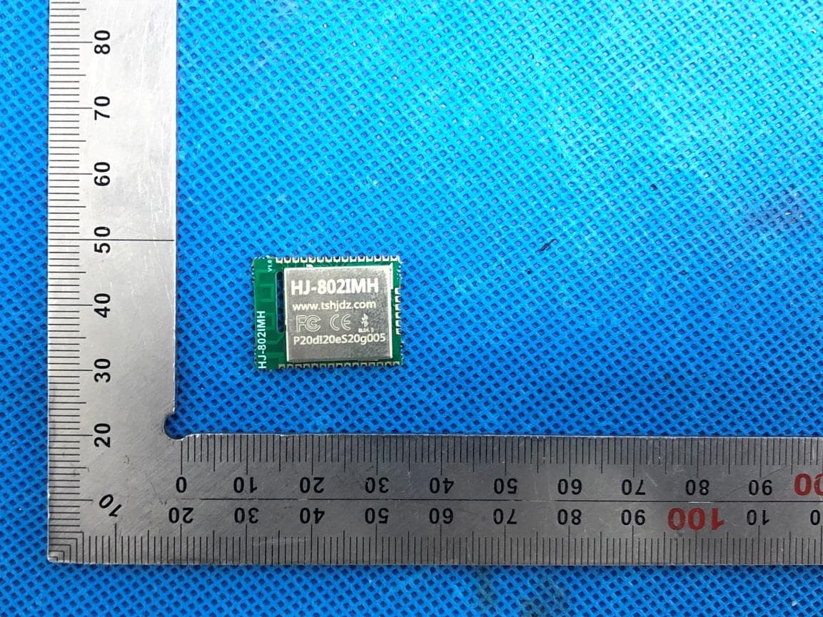
Click to zoom
Application Details
- Equipment Class
- DTS - Digital Transmission System
- Date of Grant
- Nov 05, 2020
- Application Purpose
- Original Equipment
- Date of Application
- Nov 05, 2020
- Equipment Note
- Bluetooth 4.2 ultra-low power module
- Frequency Range
- 2402.00000000 - 2480.00000000
- Country
- China
Documents & Files
Document Text
Text extracted from the exhibit documents filed with the FCC. Open a document above to read the original.
Users Manual
Copyright © 2015 Nordic Semiconductor ASA. All rights reserved. Reproduction in whole or in part is prohibited without the prior written permission of the copyright holder. nRF51802 Multiprotocol Bluetooth® low energy/2.4 GHz RF System on Chip Product Specification v1.2 Key Features •2.4 GHz transceiver • -91 dBm sensitivity in Bluetooth® low energy mode • 250 kbps, 1 Mbps, 2 Mbps supported data rates • TX Power -20 to +4 dBm in 4 dB steps • TX Power -35 dBm Whisper mode • 13 mA peak RX, 10.5 mA peak TX (0 dBm) • 10 mA peak RX, 8 mA peak TX (0 dBm) with DC/DC • RSSI (1 dB resolution) • ARM® Cortex™-M0 32 bit processor • 275 μA/MHz running from flash memory • 150 μA/MHz running from RAM • Serial Wire Debug (SWD) • S100 series SoftDevice ready •Memory • 256 kB embedded flash program memory • 16 kB RAM • On-air compatibility with nRF24L series • Flexible Power Management • Supply voltage range 1.8 V to 3.6 V • 7.7 μs wake-up using 16 MHz RCOSC • 0.6 μA at 3 V OFF mode • 1.2 μA at 3 V in OFF mode + 1 region RAM retention • 3 μA at 3 V ON mode, all blocks IDLE • 8/9/10 bit ADC - 8 configurable channels • 31 General Purpose I/O Pins • One 32 bit and two 16 bit timers with counter mode •SPI Master/Slave • Low power comparator • Temperature sensor • Two-wire Master (I2C compatible) •UART (CTS/RTS) • CPU independent Programmable Peripheral Interconnect (PPI) • Quadrature Decoder (QDEC) • AES HW encryption • Real Timer Counter (RTC) • Package variants: • QFN48 package, 6 x 6 mm • QFN32 package, 5 x 5 mm Applications • Computer peripherals and I/O devices •Mouse •Keyboard • Multi-touch trackpad • Interactive entertainment devices •Remote control •Gaming controller •Beacons • Personal Area Networks • Health/fitness sensor and monitor devices • Medical devices • Key-fobs + wrist watches • Remote control toys Page 2 nRF51802 Product Specification v1.2 Liability disclaimer Nordic Semiconductor ASA reserves the right to make changes without further notice to the product to improve reliability, function or design. Nordic Semiconductor ASA does not assume any liability arising out of the application or use of any product or circuits described herein. Life support applications Nordic Semiconductor’s products are not designed for use in life support appliances, devices, or systems where malfunction of these products can reasonably be expected to result in personal injury. Nordic Semiconductor ASA customers using or selling these products for use in such applications do so at their own risk and agree to fully indemnify Nordic Semiconductor ASA for any damages resulting from such improper use or sale. Contact details For your nearest distributor, please visit www.nordicsemi.com. Information regarding product updates, downloads, and technical support can be accessed through your My Page account on our home page. RoHS and REACH statement Nordic Semiconductor's products meet the requirements of Directive 2002/95/EC of the European Parliament and of the Council on the Restriction of Hazardous Substances (RoHS) and the requirements of the REACH regulation (EC 1907/2006) on Registration, Evaluation, Authorization and Restriction of Chemicals. The SVHC (Substances of Very High Concern) candidate list is continually being updated. Complete hazardous substance reports, material composition reports and latest version of Nordic's REACH statement can be found on our website www.nordicsemi.com. Main office: Phone: +47 72 89 89 00 Fax: +47 72 89 89 89 Otto Nielsens veg 12 7052 Trondheim Norway Mailing address: Nordic Semiconductor P.O. Box 2336 7004 Trondheim Norway Page 3 nRF51802 Product Specification v1.2 Datasheet Status Revision History StatusDescription Objective Product Specification (OPS) This product specification contains target specifications for product development. Preliminary Product Specification (PPS) This product specification contains preliminary data; supplementary data may be published from Nordic Semiconductor ASA later. Product Specification (PS) This product specification contains final product specifications. Nordic Semiconductor ASA reserves the right to make changes at any time without notice in order to improve design and supply the best possible product. DateVersionDescription May 20161.2Added the QFN32 package variant. Added content: •Section 2.2.2 “Pin assignment QFN32” •Section 9.2 “QFN32 package” on page 63 •Section 11.2 “Reference design schematics” on page 72 •Section 11.4 “QCAA QFN32 package” on page 79 Updated content: • Key features on the front page •Section 3.7 “GPIO” on page 26 •Section 8.2 “Power management” on page 40 •Section 8.5.7 “Antenna matching network requirements” on page 50 •Section 10.6 “Code ranges and values” on page 67 •Section 10.7 “Product options” on page 69 February 20161.1Updated content: •Section 8.5.7 “Antenna matching network requirements” on page 50 February 20161.0Updated content: •Chapter 7 “Operating conditions” on page 34 •Section 8.1.5 “32.768 kHz crystal oscillator (32k XOSC)” on page 38 •Section 8.1.6 “32.768 kHz RC oscillator (32k RCOSC)” on page 39 •Section 8.5.2 “Radio current consumption with DC/DC disabled” on page 45 •Section 8.5.3 “Radio current consumption with DC/DC enabled” on page 46 •Section 8.15 “Temperature sensor (TEMP)” on page 57 Page 4 nRF51802 Product Specification v1.2 November 20150.7Updated content: •Section 1.1 “Required reading” on page 7 •Chapter 6 “Absolute maximum ratings” on page 33 •Chapter 7 “Operating conditions” on page 34 •Section 8.1.2 “16 MHz crystal oscillator (16M XOSC)” on page 36 •Section 8.1.4 “16 MHz RC oscillator (16M RCOSC)” on page 38 •Chapter 8.1.5 “32.768 kHz crystal oscillator (32k XOSC)” on page 38 •Section 8.2 “Power management” on page 40 •Section 8.4 “CPU” on page 44 •Section 8.5.4 “Transmitter specifications” on page 47 •Section 8.5.5 “Receiver specifications” on page 48 •Section 8.8 “Serial Peripheral Interface Slave (SPIS) specifications” on page 52 •Section 8.12 “Analog to Digital Converter (ADC) sp…
Text truncated - open the document above for the full version.
Cover Letter(s)
Tangshan HongJia electronic technology Co., LTD. RE FCC ID: 2AGPMHJ-802IMH To the certification reviewer: We are hereby applying for full modular approval of the above-referenced FCC ID, based on compliance with all of the criteria as detailed below. Sincerely, Liu Ying Part 15 Unlicensed Single Modular Transmitter Approval Justification per 15.212 Requirement per 15.212 reference (i) The radio elements of the modular transmitter must have their own RF shielding. Shielding is provided by a metal cover over the circuitry. (ii) The modular transmitter must have buffered modulation/data inputs (if such inputs are provided. All modulation and data inputs are buffered by circuitry on the transmitter chip. (iii) The modular transmitter must have its own power supply regulation. Power supply regulation is provided by circuitry on the transmitter chip. (iv) The modular transmitter must comply with the antenna and transmission system requirements of §§ 15.203, 15.204(b) and 15.204(c). The antenna is permanently attached. (v) The modular transmitter must be tested in a stand-alone configuration, i.e., the module must not be inside another device during testing for compliance with Part 15 parameters. Testing was performed with the module extended outside of the host on a special extender board, as shown in the test setup photos. / Testing was performed in a stand-alone configuration as shown in the test setup photos. (vi) The modular transmitter must be equipped with either a permanently affixed label or must be capable of electronically displaying its FCC identification number. If the FCC ID is not visible when the module is installed inside another device, then the outside of the device into which the module is installed must also display a label referring to the enclosed module. A sample of the host label is provided as an exhibit, showing the FCC identifier of the module. Tangshan HongJia electronic technology Co., LTD. (vii) The modular transmitter must comply with any specific rules or operating requirements that ordinarily apply to a complete transmitter and the manufacturer must provide adequate instructions along with the module to explain any such requirements. A copy of these instructions must be included in the application for equipment authorization. The module complies fully with the operating requirements of Part 15 section [...] as demonstrated in the test report exhibit. (viii) The modular transmitter must comply with any applicable RF exposure requirements in its final configuration. This module operates under Part 15 section [15.247], which s exempt from RF exposure evaluation owing to the very low operating power:
External Photos
External Photos EXTERNAL VIEW-1 OF EUT EXTERNAL VIEW-2 OF EUT EXTERNAL VIEW-3 OF EUT EXTERNAL VIEW-4 OF EUT EXTERNAL VIEW-5 OF EUT EXTERNAL VIEW-6 OF EUT
ID Label/Location Info
FCC ID Label Location FCC ID:2AGPMHJ-802IMH
Internal Photos
Internal Photos INTERNAL VIEW-1 OF EUT INTERNAL VIEW-2 OF EUT INTERNAL VIEW-3 OF EUT BT Antenna
Operational Description
Tangshan HongJia electronic technology Co., LTD. Declaration concerning Antenna Specification It is hereby declared that the product Model No.: HJ-802IMH, HJ-801IMH, HJ-803IMH, HJ-805IMH FCC ID: 2AGPMHJ-802IMH fulfills the requirement in FCC test relating to the antenna type. The device specified above confirms to the FCC recommendations for internal antenna type(s) described below: Type of antenna: PCB Antenna Gain of the antenna: 2.8dBi Frequency range: 2402-2480 MHz The mounting of the antenna is fixed to the radio module and no other antenna should be used. Company name: Tangshan HongJia electronic technology Co., LTD. Address: 352 No. 2 # building power springs in Qianxi County, Tangshan City,Hebei Province Date: 2020-11-05 Signature:
RF Exposure Info
RF EXPOSURE EVALUATION 1. PRODUCT INFORMATION Product Description Bluetooth 4.2 ultra-low power module Model Name HJ-802IMH FCC ID 2AGPMHJ-802IMH 2. EVALUATION METHOD According to 447498 D01 General RF Exposure Guidance v05 The 1-g and 10-g SAR test exclusion thresholds for 100 MHz to 6 GHz at test separation distances ≤ 50 mm are determined by: [(max. power of channel, including tune-up tolerance, mW)/(min. test separation distance, mm)] ·[√f(GHz)] ≤ 3.0 for 1-g SAR and ≤ 7.5 for 10-g extremity SAR. Where f(GHz) is the RF channel transmit frequency in GHz Power and distance are rounded to the nearest mW and mm before calculation 3. CALCULATION BLE: P t =-5.808dBm=0.26mW The value of the Maximum output power P t is referred to the test report of the CFR47 §15.247. The result for RF exposure evaluation SAR=(0.26mW /5mm) .[√2.402GHz)]= 0.08<3.0 for 1-g SAR and ≤ 7.5 for 10-g extremity SAR. 4. CONCLUSION The SAR evaluation is not required.
Test Report
Page 1 of 46 FCC Test Report Report No.: AGC00806201001FE02 FCC ID : 2AGPMHJ-802IMH APPLICATION PURPOSE : Original Equipment PRODUCT DESIGNATION : Bluetooth 4.2 ultra-low power module BRAND NAME : HongJia MODEL NAME : HJ-802IMH, HJ-801IMH, HJ-803IMH, HJ-805IMH APPLICANT : Tangshan HongJia electronic technology Co., LTD. DATE OF ISSUE : Nov. 02, 2020 STANDARD(S) : FCC Part 15.247 REPORT VERSION : V1.0 Attestation of Global Compliance (Shenzhen) Co., Ltd Report No.: AGC00806201001FE02 Page 2 of 46 REPORT REVISE RECORD Report Version Revise Time Issued Date Valid Version Notes V1.0 / Nov. 02, 2020 Valid Initial Release Report No.: AGC00806201001FE02 Page 3 of 46 TABLE OF CONTENTS 1. VERIFICATION OF COMPLIANCE ............................................................................................................... 5 2. GENERAL INFORMATION ............................................................................................................................ 6 2.1. PRODUCT DESCRIPTION ...................................................................................................................... 6 2.2. TABLE OF CARRIER FREQUENCYS ..................................................................................................... 6 2.3. RELATED SUBMITTAL(S)/GRANT(S) .................................................................................................... 7 2.4. TEST METHODOLOGY ........................................................................................................................... 7 2.5. SPECIAL ACCESSORIES ....................................................................................................................... 7 2.6. EQUIPMENT MODIFICATIONS .............................................................................................................. 7 2.7. ANTENNA REQUIREMENT ..................................................................................................................... 7 3. MEASUREMENT UNCERTAINTY ................................................................................................................. 8 4. DESCRIPTION OF TEST MODES ................................................................................................................. 9 5. SYSTEM TEST CONFIGURATION ............................................................................................................. 10 5.1. CONFIGURATION OF TESTED SYSTEM ............................................................................................. 10 5.2. EQUIPMENT USED IN TESTED SYSTEM ............................................................................................ 10 5.3. SUMMARY OF TEST RESULTS ............................................................................................................ 10 6. TEST FACILITY ........................................................................................................................................... 11 7. PEAK OUTPUT POWER ............................................................................................................................. 12 7.1. MEASUREMENT PROCEDURE ........................................................................................................... 12 7.2. TEST SET-UP (BLOCK DIAGRAM OF CONFIGURATION) .................................................................. 12 7.3. LIMITS AND MEASUREMENT RESULT ............................................................................................... 13 8. 6 DB BANDWIDTH ...................................................................................................................................... 15 8.1. MEASUREMENT PROCEDURE ........................................................................................................... 15 8.2. TEST SET-UP (BLOCK DIAGRAM OF CONFIGURATION) .................................................................. 15 8.3. LIMITS AND MEASUREMENT RESULTS ............................................................................................. 15 9. CONDUCTED SPURIOUS EMISSION ........................................................................................................ 17 9.1. MEASUREMENT PROCEDURE ........................................................................................................... 17 9.2. TEST SET-UP (BLOCK DIAGRAM OF CONFIGURATION) .................................................................. 17 9.3. MEASUREMENT EQUIPMENT USED .................................................................................................. 17 9.4. LIMITS AND MEASUREMENT RESULT ............................................................................................... 17 10. MAXIMUM CONDUCTED OUTPUT POWER SPECTRAL DENSITY ....................................................... 25 Report No.: AGC00806201001FE02 Page 4 of 46 10.1. MEASUREMENT PROCEDURE ......................................................................................................... 25 10.2. TEST SET-UP (BLOCK DIAGRAM OF CONFIGURATION) ................................................................ 25 10.3. MEASUREMENT EQUIPMENT USED ................................................................................................ 25 10.4. LIMITS AND MEASUREMENT RESULT ............................................................................................. 25 11. RADIATED EMISSION ............................................................................................................................... 27 11.1. MEASUREMENT PROCEDURE ......................................................................................................... 27 11.2. TEST SETUP ....................................................................................................................................... 28 11.3. LIMITS AND MEASUREMENT RESULT ............................................................................................. 29 11.4. TEST…
Text truncated - open the document above for the full version.
Test Report
Report No.: AGC00806201001FE02 Page 43 of 46 APPENDIX A: PHOTOGRAPHS OF TEST SETUP RADIATED EMISSION TEST SETUP BELOW 1GHZ RADIATED EMISSION TEST SETUP ABOVE 1GHZ Report No.: AGC00806201001FE02 Page 44 of 46 LINE CONDUCTED EMISSION TEST SETUP CONDUCTED TEST SETUP Report No.: AGC00806201001FE02 Page 45 of 46 APPENDIX B: PHOTOGRAPHS OF EUT EXTERNAL VIEW-1 OF EUT EXTERNAL VIEW-2 OF EUT Report No.: AGC00806201001FE02 Page 46 of 46 EXTERNAL VIEW-3 OF EUT EXTERNAL VIEW-4 OF EUT Report No.: AGC00806201001FE02 Page 47 of 46 EXTERNAL VIEW-5 OF EUT EXTERNAL VIEW-6 OF EUT Report No.: AGC00806201001FE02 Page 48 of 46 INTERNAL VIEW-1 OF EUT INTERNAL VIEW-2 OF EUT Report No.: AGC00806201001FE02 Page 49 of 46 INTERNAL VIEW-3 OF EUT ----END OF REPORT---- BT Antenna Conditions of Issuance of Test Reports 1. All samples and goods are accepted by the Attestation of Global Compliance (Shenzhen) Co., Ltd (the “Company”) solely for testing and reporting in accordance with the following terms and conditions. The company provides its services on the basis that such terms and conditions constitute express agreement between the company and any person, firm or company requesting its services (the “Clients”). 2. Any report issued by Company as a result of this application for testing services (the “Report”) shall be issued in confidence to the Clients and the Report will be strictly treated as such by the Company. It may not be reproduced either in its entirety or in part and it may not be used for advertising or other unauthorized purposes without the written consent of the Company. The Clients to whom the Report is issued may, however, show or send it, or a certified copy thereof prepared by the Company to its customer, supplier or other persons directly concerned. The Company will not, without the consent of the Clients, enter into any discussion or correspondence with any third party concerning the contents of the Report, unless required by the relevant governmental authorities, laws or court orders. 3.The Company shall not be called or be liable to be called to give evidence or testimony on the Report in a court of law without its prior written consent, unless required by the relevant governmental authorities, laws or court orders. 4. The non-CMA report issued by AGC is only permitted to be used by the client as internal reference use and shall not be used for public demonstration purpose. 5. In the event of the improper use of the report as determined by the Company, the Company reserves the right to withdraw it, and to adopt any other additional remedies which may be appropriate. 6. Samples submitted for testing are accepted on the understanding that the Report issued cannot form the basis of, or be the instrument for, any legal action against the Company. 7. The Company will not be liable for or accept responsibility for any loss or damage however arising from the use of information contained in any of its Reports or in any communication whatsoever about its said tests or investigations. 8.Clients wishing to use the Report in court proceedings or arbitration shall inform the Company to that effect prior to submitting the sample for testing. 9. The Company is not responsible for recalling the electronic version of the original report when any revision is made to them. The Client assumes the responsibility to providing the revised version to any interested party who uses them. 10. Subject to the variable length of retention time for test data and report stored hereinto as otherwise specifically required by individual accreditation authorities, the Company will only keep the supporting test data and information of the test report for a period of six years. The data and information will be disposed of after the aforementioned retention period has elapsed. Under no circumstances shall we provide any data and information which has been disposed of after retention period. Under no circumstances shall we be liable for damage of any kind, including (but not limited to) compensatory damages, lost profits, lost data, or any form of special, incidental, indirect, consequential or punitive damages of any kind, whether based on breach of contract of warranty, tort (including negligence), product liability or otherwise, even if we are informed in advance of the possibility of such damages.
Test Setup Photos
Test Setup Photos RADIATED EMISSION TEST SETUP BELOW 1GHZ RADIATED EMISSION TEST SETUP ABOVE 1GHZ LINE CONDUCTED EMISSION TEST SETUP CONDUCTED TEST SETUP
Contact Information
Applicant
Liu Ying
Test Firm
Attestation of Global Compliance (Shenzhen) Co., LDoris Li
[email protected]+86-755-25234088
Technical Specifications
| # | Rule Parts | Frequency Range | Power Output |
|---|---|---|---|
| 1 | 15C | 2.40 GHz - 2.48 GHz | 260.00 µW |
Other Applications from Tangshan HongJia electronic technology co., LTD.
2AGPM-HJ568IMH
May 08, 2026Bluetooth(BLE 6.1) ultra-low power module with integrated antenna
Equipment Class
DTS - Digital Transmission System
2AGPMHJ-840
Mar 04, 2021Bluetooth 5.1 ultra-low power module
Equipment Class
DTS - Digital Transmission System
2AGPMHJ-580B
Dec 15, 2015HongJia electronic bluetooth BLE4.0 ultra-low power module
Equipment Class
DTS - Digital Transmission System