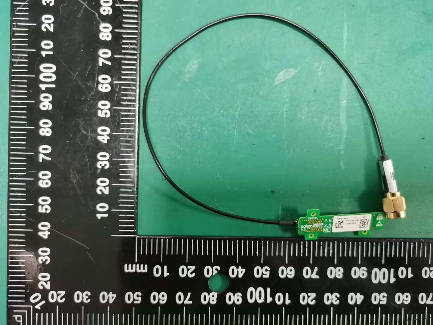
2AGPT-PLNX2Linux Communication Board
SolarEdge Technologies Ltd
Click to zoom
Application Details
- Equipment Class
- DTS - Digital Transmission System
- Date of Grant
- Mar 21, 2022
- Application Purpose
- Original Equipment
- Date of Application
- Mar 21, 2022
- Equipment Note
- Linux Communication Board
- Frequency Range
- 2412.00000000 - 2462.00000000
- Company
- SolarEdge Technologies Ltd
- Country
- Israel
Documents & Files
Document Text
Text extracted from the exhibit documents filed with the FCC. Open a document above to read the original.
Users Manual
ConfigurationGuide CommunicationBoardfor InverterswithSetApp Configuration Version1.4 Chapter1:Activating,Commissioningand ConfiguringtheSystem Afterthesolarsystemisinstalled,itisimportanttoactivateandcommissionthesolar system.Activationandcommissionofthesystemisperformedusingtheinverter SetAppmobileapplication. Duringtheactivationandcommissioning,theinverterdiscoversandcommunicates withallconnectedcomponentsinthesolarsystem,suchas:optimizers,peripheral communicationdevicesandotherlinkedinverters.Whencommissioningisperformed, theuserisrequiredtosetthegridparametersandbackupVoltageinformation(ifused). Beforestartingtheactivationandcommissioning,verifytheallthecommunication hardwareisproperlyconnect.Forcommunicationoptions,referto:SettingUp CommunicationwiththeMonitoringPlatformonpage6. Beforearrivingatthesite,downloadSolarEdgeSetAppapplicationtoyourmobile devicefromAppleAppStoreorGooglePlay. Beforeactivationandcommissioning,downloadtheSetAppapplicationfrom: FordownloadingSetApp,Internetconnection,one-timeregistrationandloggingare required.NoregistrationisrequiredforusingtheSetApp. Step1:ActivatingtheInstallation Duringsystemactivation,aWi-Ficonnectioniscreatedbetweenthemobiledeviceand theinverterandthesystemfirmwareisupgraded. Beforeactivation Download,register(firsttimeonly) andlogintoSetApponyourmobiledevice. Verifythattheapplicationisupdatedwiththelatestversion. Chapter1:Activating,CommissioningandConfiguringtheSystem1 CommunicationBoardforInverterswithSetAppConfiguration Ifapplicable,turnonalldevices(battery,EnergyMeter)connectedtotheinverter,so thatthedevicesmaybeauto-detected. Toactivatetheinverter: 1.Turn-on theAC circuitbreakeronthemaindistributionpanel. 2. OpenSetAppandfollowtheon-screeninstructions(scantheinverterbarcode; movetheON/OFF/PswitchtoPpositionfor2secondsandrelease). SetAppcreatesaWi-Ficonnection,upgradestheinverterfirmwareandactivatesthe inverter. 3.Whentheactivationiscomplete,dooneofthefollowing: SelectConnecttoAnotherDevicetocontinueactivatingadditionalinverters. SelectStartCommissioningforpairingandothersystemconfiguration. Step2:CommissioningandConfiguringthe Installation ThissectiondescribeshowtousetheSetAppmenusforcommissioningand configuringtheinvertersettings. Menusmayvaryinyourapplicationdependingonyoursystemtype. ToaccesstheCommissioningscreen: Dooneofthefollowing: Duringfirsttimeinstallation:Uponactivationcompletion,intheSetApp,tapStart Commissioning. Iftheinverterhasalreadybeenactivatedandcommissioned: IfnotalreadyON-turnONACtotheinverterbyturningONthecircuitbreaker onthemaindistributionpanel. OpenSetAppandfollowtheon-screeninstructions(scantheinverterQRcode, movetheON/OFF/PswitchtoPpositionfor2secondsandrelease). ThemobiledevicecreatesaWi-Ficonnectionwiththeinverteranddisplaysthe mainCommissioningscreen. SettingCountry,GridandLanguage Theinvertermustbeconfiguredtothepropersettingsinordertoensurethatit complieswiththecountrygridcodeandfunctions.Unlessthesesettingsareselected, theinverterwillnotstartproduction. CommunicationBoardforInverterswithSetAppConfiguration 2Step2:CommissioningandConfiguringtheInstallation 1. FromtheCommissioningscreen,selectCountry&Grid. 2. FromtheCountry&Griddrop-downlist,selecttherequiredoptionandtapSet Country&Grid. 3.Ifrelevant,fromtheLanguagedrop-downlist,selectyourlanguageandtapSet Language. 4.Tosavetheinformationtoaread-onlyfile,tapthePDF icon(iOS)ortheJPEGicon (Android)atthebottomofthescreen. Pairing 1. FromtheCommissioningmenu,selectPairing. 2.TapStartPairing. 3. WhenPairingCompleteisdisplayed,thesystemstartupprocessbegins: SincetheinverterisON,thePowerOptimizersstartproducingpowerandthe inverterstartsconvertingAC. WARNING! WhenyouturnONtheinverterON/OFF/Pswitch,theDCcablescarryahigh VoltageandthePowerOptimizersnolongeroutputasafeoutput. WhentheinverterstartsconvertingpoweraftertheinitialconnectiontotheAC,the inverterentersWakeupmodeuntilitsworkingvoltageisreached.Thismodeis indicatedbytheflickeringgreeninverterLED. Whenworkingvoltageisreached,theinverterentersProductionmodeand producespower.ThesteadilylitgreeninverterLEDindicatesthismode. 4.TapOKtoreturntotheCommissioningmenu. Chapter1:Activating,CommissioningandConfiguringtheSystem3 CommunicationBoardforInverterswithSetAppConfiguration Communication Communicationsettingscanbeconfiguredonlyaftercommunicationconnectionsare complete.RefertoSettingUpCommunicationwiththeMonitoringPlatformonpage6. SelectMonitoringCommunicationtoconfigurecommunicationwiththe monitoringplatform. SelectSiteCommunicationtoconfigurecommunicationbetweenmultiple SolarEdgedevicesorexternalnon-SolarEdgedevices,suchasbatteriesorloggers. PowerControl PowercontroloptionsaredetailedinthePowerControlApplicationNote,availableon theSolarEdgewebsiteat:https://www.solaredge.com/sites/default/files/application_ note_power_control_configuration.pdf. TheGridControloptionmaybedisabled.Enablingitopensadditionaloptionsinthe menu. TheEnergyManageroptionisusedforsettingpowerexportlimitation,asdescribedin theExportLimitationApplicationNote,availableontheSolarEdgewebsiteat: https://www.solaredge.com/sites/default/files/feed-in_limitation_application_note.pdf. Step3:VerifyingProperActivationand Commissioning 1.SelectInformationandverifythatthecorrectfirmwareversionsareinstalledon eachinverter. 2.SelectStatusandverifythatinverterisoperatingandproducingpower. 3.Verifythatadditionalconfigurationswereproperlysetbyviewingtherelevant Statusscreens. 4.VerifythatthegreeninverterLED issteadilylit. YourSolarEdgepowerharvestingsystemisnowoperational. CommunicationBoardforInverterswithSetAppConfiguration 4Step3:VerifyingProperActivationandCommissioning CommunicationStatusIndications Thisscreendisplaysthestatusofconnectionoption(s):LAN,RS485,Wi-Fi,orcellular Plug-in. Foreachcommunicationoption,oneofthefollowingstatusesisdisplayed: Connected:Theinverterestablishedasuccessfulconnectionandcommunication withthespecifiedserverport NC:NotConnected S_OK:Theconnectiontothemonitoringplatformissuccessful(shouldappearonlyif theisconnectedtotheser…
Text truncated - open the document above for the full version.
Cover Letter(s)
SolarEdge Technologies Ltd 1 HaMada Street, Herzeliya 467335 Israel. Tel: +97299576620 Extension: 271 Fax: +97299576591 Email: [email protected] QA-FR-170-B 7/29/2014 FCC Authorization Date: 2021-12-17 FEDERAL COMMUNICATIONS COMMISSIONS Authorization and Evaluation Division 7435 Oakland Mills Road Columbia, MD 21046 Subject: Agent Authorization To whom it may concern: We SolarEdge Technologies Ltd, the undersigned, hereby authorizes Shenzhen Accurate Technology Co., Ltd. to act on its behalf in all matters relating to application for Equipment authorization, including the signing of all documents relating to these matters. All acts carried out by Shenzhen Accurate Technology Co., Ltd. on our behalf shall have the same effect as our own action. We, the undersigned, hereby certify that we are not subject to a denial of federal benefits, that includes FCC benefits, pursuant to Section 5301 of the Anti-Drug Abuse Act of 1988, 21 U.S.C. 862. This authorization is valid until further written notice from the applicant. Sincerely Yours, Signature: Oren Bachar Certification Engineer
Cover Letter(s)
SolarEdge Technologies Ltd 1 HaMada Street, Herzeliya 467335 Israel Tel: +97299576620 Extension: 271 Fax: +97299576591 Email: [email protected] Modular Approval Letter Date: 2021-12-17 FEDERAL COMMUNICATIONS COMMISSIONS Authorization and Evaluation Division 7435 Oakland Mills Road Columbia, MD 21046 Dear Application Examiner, We, SolarEdge Technologies Ltd is submitting this application for certification of product named as Linux Communication Board, Model Numbers: 2AGPT-PLNX2 (FCC ID: 2AGPT-PLNX2). It is seeking modular approval. The radio meets the requirements for modular approval as detailed in FCC 15.212. Compliance to each of the requirements is described below: 1. “The modular transmitter must have its own RF shielding.” Yes, it is fulfilled. The radio portion of the module has its own RF shielding. The shielding is installed at the factory. Please see the EUT photos. 2. “The modular transmitter must have buffered modulation/data inputs.” Yes, it is fulfilled. The EUT has buffered data inputs to insure compliance with Part 15 requirements under conditions of excessive data rates or over modulation. Please see the Schematics exhibit. 3. “The modular transmitter must have its own power supply regulation.” Yes, it is fulfilled. The EUT has its own power supply regulation to insure compliance. 4. “The modular transmitter must comply with the antenna requirements of Section 15.203 and 15.204(c).” Yes. The EUT has two antenna(Chip antenna & External Dipole Antenna) design. 5. “The modular transmitter must be tested in a stand-alone configuration.” Yes, it is fulfilled. The EUT was tested in a stand-alone configuration. 6. “The modular transmitter must be labeled with its own FCC ID number.” Yes, it is fulfilled. The module will be labeled with its own FCC ID number. Please see FCC ID label & location exhibit. 7. “The modular transmitter must comply with any specific rule or operating requirements applicable to the transmitter and the manufacturer must provide adequate instructions along with the module to explain any such requirements.” Yes, it is fulfilled. The necessary explanation to be complied with this requirement is contained in the user manual, and please refer to the User manual. 8. “The modular transmitter must comply with any applicable RF exposure requirements.” Yes, the module is intended to use in distance more that 20cm. FCC RF exposure requirement satisfied with 47CFR §2.1091. Please contact me if you have additional questions. Your attention to this matter is greatly appreciated. Sincerely Yours, Signature: Oren Bachar Certification Engineer
Cover Letter(s)
SolarEdge Technologies Ltd 1 HaMada Street, Herzeliya 467335 Israel. Tel: +97299576620 Extension: 271 Fax: +97299576591 Email: [email protected] FCC Confidential Authorization Date: 2021-12-17 FEDERAL COMMUNICATIONS COMMISSIONS Authorization and Evaluation Division 7435 Oakland Mills Road Columbia, MD 21046 Subject: Confidentiality Request regarding application for certification of FCC ID: 2AGPT-PLNX2 In accordance with Sections 0.457 and 0.459 of the Commission’s Rules, SolarEdge Technologies Ltd hereby requests long-term confidential treatment of information accompanying this application as outlined below: Block Diagram Schematics Operation Description The above materials contain proprietary and confidential information not customarily released to the public. The public disclosure of these materials provides unjustified benefits to its competitors in the market. Sincerely Yours, Signature: Oren Bachar Certification Engineer
External Photos
Shenzhen Accurate Technology Co., Ltd. Project No.: SZ1210910-52986E-RF External Photos Page 1 of 1 External Photos
ID Label/Location Info
Shenzhen Accurate Technology Co., Ltd. Project No.: SZ1210910-52986E-RF LABEL AND LOCATION Page 1 of 1 FCC ID Label FCC ID Label Location Information The label shown shall be permanently affixed at a conspicuous location on the device and be readily visible to the user at the time purchase (Labeling requirements per 2.925)
Internal Photos
Shenzhen Accurate Technology Co., Ltd. Project No.: SZ1210910-52986E-RF Internal Photos Page 1 of 5 Internal photos Shenzhen Accurate Technology Co., Ltd. Project No.: SZ1210910-52986E-RF Internal Photos Page 2 of 5 Shenzhen Accurate Technology Co., Ltd. Project No.: SZ1210910-52986E-RF Internal Photos Page 3 of 5 Shenzhen Accurate Technology Co., Ltd. Project No.: SZ1210910-52986E-RF Internal Photos Page 4 of 5 Chip Antenna SMA Antenna Shenzhen Accurate Technology Co., Ltd. Project No.: SZ1210910-52986E-RF Internal Photos Page 5 of 5 Ant Port
RF Exposure Info
Shenzhen Accurate Technology Co., Ltd. Report No.: SZ1210910-52986E-RFA Version 20: 2021-11-09 Page 13 of 82 FCC&RSS- 2.4G Wi-Fi FCC §15.247 (i) & §2.1091- MAXIMUM PERMISSIBLE EXPOSURE (MPE) Applicable Standard According to subpart 15.247 (i) and subpart 2.1091 systems operating under the provisions of this section shall be operated in a manner that ensures the public is not exposed to RF energy level in excess of the communication guidelines. Limits for General Population/Uncontrolled Exposure Limits for General Population/Uncontrolled Exposure Frequency Range (MHz) Electric Field Strength (V/m) Magnetic Field Strength (A/m) Power Density (mW/cm 2 ) Averaging Time (Minutes) 0.3-1.34 614 1.63 *(100) 30 1.34-30 824/f 2.19/f *(180/f 2 ) 30 30-300 27.5 0.073 0.2 30 300-1500 / / f/1500 30 1500-100,000 / / 1.0 30 f = frequency in MHz * = Plane-wave equivalent power density a) Result Calculated Formulary: Predication of MPE limit at a given distance S = 2 4R PG π S = power density (in appropriate units, e.g. mW/cm 2 ) P = power input to the antenna (in appropriate units, e.g., mW). G = power gain of the antenna in the direction of interest relative to an isotropic radiator, the power gain factor, is normally numeric gain. R = distance to the center of radiation of the antenna (appropriate units, e.g., cm) Mode Frequenc y (MHz) Antenna Gain Tune up conducted power Evaluation Distance (cm) Power Density (mW/cm 2 ) MPE Limit (mW/cm 2 ) (dBi) (numeric) (dBm) (mW) Chip antenna 2412-2462 0.5 1.12 16.5 44.67 20 0.010 1 External antenna 2412-2462 5.0 3.16 23.0 199.53 20 0.126 1 Note: To maintain compliance with the FCC’s RF exposure guidelines, place the equipment at least 20cm from nearby persons. Result: Compliance
Test Report
Note: This report may contain data that are not covered by the A2LA accreditatio ★ n and are marked with an asterisk “ ”. Shenzhen Accurate Technology Co., Ltd. is not responsible for the authenticity of any test data provided by the applicant. Data included from the applicant that may affect test results are marked with an asterisk ’*’. Customer model name, addresses, names, trademarks etc. are not considered data. This report cannot be reproduced except in full, without prior written approval of the Company. Unless otherwise stated the results shown in this test report refer only to the sample(s) tested. This report is valid only with a valid digital signature. The digital signature may be available only under the Adobe software above version 7.0. Shenzhen Accurate Technology Co., Ltd. 1/F., Building A, Changyuan New Material Port, Science & Industry Park, Nanshan District, Shenzhen, Guangdong, P.R. China Tel: +86 755-26503290 Fax: +86 755-26503396 Web: www.atc-lab.com Version 20: 2021-11-09 Page 1 of 81 FCC&RSS- 2.4G Wi-Fi TEST REPORT Applicant Name : SolarEdge Technologies Ltd Address : 1 HaMada Street, Herzeliya 467335 Israel Report Number : SZ1210910-52986E-RFA FCC ID: 2AGPT-PLNX2 IC 20916-PLNX2 Test Standard (s) FCC PART 15.247; RSS-GEN ISSUE 5, FEBRUARY 2021 AMENDMENT 2; RSS-247, ISSUE 2, FEBRUARY 2017 Sample Description Product Type: Linux Communication Board Model No.: 2AGPT-PLNX2 Multiple Model(s) No.: N/A Trade Mark: N/A Date Received: 2021/09/10 Date of Test: 2021/12/01~2022/01/06 Report Date: 2021/01/13 Test Result: Pass* * In the configuration tested, the EUT complied with the standards above. Prepared and Checked By: Approved By: Ting Lü Robert Li EMC Engineer EMC Engineer Shenzhen Accurate Technology Co., Ltd. Report No.: SZ1210910-52986E-RFA Version 20: 2021-11-09 Page 2 of 81 FCC&RSS- 2.4G Wi-Fi TABLE OF CONTENTS GENERAL INFORMATION ....................................................................................................................................... 4 PRODUCT DESCRIPTION FOR EQUIPMENT UNDER TEST (EUT) ..................................................................................... 4 OBJECTIVE ................................................................................................................................................................... 4 TEST METHODOLOGY .................................................................................................................................................. 4 MEASUREMENT UNCERTAINTY .................................................................................................................................... 5 SYSTEM TEST CONFIGURATION .......................................................................................................................... 6 DESCRIPTION OF TEST CONFIGURATION ...................................................................................................................... 6 EQUIPMENT MODIFICATIONS ....................................................................................................................................... 6 EUT EXERCISE SOFTWARE .......................................................................................................................................... 6 DUTY CYCLE ............................................................................................................................................................... 7 SUPPORT EQUIPMENT LIST AND DETAILS .................................................................................................................... 8 EXTERNAL I/O CABLE .................................................................................................................................................. 9 BLOCK DIAGRAM OF TEST SETUP ................................................................................................................................ 9 SUMMARY OF TEST RESULTS ............................................................................................................................. 11 TEST EQUIPMENT LIST ......................................................................................................................................... 12 FCC §15.247 (I) & §2.1091- MAXIMUM PERMISSIBLE EXPOSURE (MPE)........................................................ 13 APPLICABLE STANDARD ............................................................................................................................................ 13 RESULT ...................................................................................................................................................................... 13 RSS-102 § 2.5.2 –EXEMPTION LIMITS FOR ROUTINE EVALUATION-RF EXPOSURE EVALUATION 14 APPLICABLE STANDARD ............................................................................................................................................ 14 §15.203 & RSS-GEN §6.8 ANTENNA REQUIREMENT ........................................................................................ 15 APPLICABLE STANDARD ............................................................................................................................................ 15 ANTENNA CONNECTOR CONSTRUCTION .................................................................................................................... 16 §15.207 (A) & RSS-GEN §8.8 AC LINE CONDUCTED EMISSIONS .................................................................. 17 APPLICABLE STANDARD ............................................................................................................................................ 17 EUT SETUP ................................................................................................................................................................ 18 EMI TEST RECEIVER SETUP .............................................................................................…
Text truncated - open the document above for the full version.
Test Setup Photos
Shenzhen Accurate Technology Co., Ltd. Project No.: SZ1210910-52986E-RF Test Photos Page 1 of 2 Photo of Conducted Emission Measurement Shenzhen Accurate Technology Co., Ltd. Project No.: SZ1210910-52986E-RF Test Photos Page 2 of 2 Photo of Radiated Emission Measurement (Below 1G) Photo of Radiated Emission Measurement (Above 1G)
Contact Information
Applicant
Rami Nataf(EMC & Radio Certification Manager)
Test Firm
Shenzhen Accurate Technology Co., Ltd.Lisa Zhang
[email protected]+86-755-26503290
Technical Specifications
| # | Rule Parts | Frequency Range | Power Output |
|---|---|---|---|
| 1 | 15C | 2.41 GHz - 2.46 GHz | 185.00 mW |
Other Applications from SolarEdge Technologies Ltd
2AGPT-ENET2
Aug 13, 2024SolarEdge Energy Net
Equipment Class
DTS - Digital Transmission System