2AH6G-ELDP30ATablet Computer
AMBIR TECHNOLOGY INC.
Click to zoom
Application Details
- Equipment Class
- DTS - Digital Transmission System
- Date of Grant
- Jan 06, 2021
- Application Purpose
- Original Equipment
- Date of Application
- Jan 06, 2021
- Equipment Note
- Tablet Computer
- Frequency Range
- 2412.00000000 - 2462.00000000
- Company
- AMBIR TECHNOLOGY INC.
- Country
- United States
Documents & Files
Document Text
Text extracted from the exhibit documents filed with the FCC. Open a document above to read the original.
Users Manual
Quickstart Guide Welcome to EntryLogic and congratulations on taking the first step in providing your visitors and employees the safety and efficiency of a visitor management system. This box contains the following: 1 EL-DP30-A Tablet Computer 1 AC Power Adapter Do not disassemble or alter your device in any way, as it may result in an electrical short, smoke, fire, electrical shock, injury to yourself or others, damage to the tablet or other property. For service or repair, please contact EntryLogic’s customer support for assistance. Do not place the product near chemicals or in a place where chemical spillage can occur. Do not allow organic solvents, suchas benzene, thinner, or deodorizers coming into contact with the screen or outer case of the device. These may cause the case to warp or discolor and may also cause the device to malfunction. Do not allow water, drinks, or metal objects come into contact with AC Power Adapter. In addition, do not use the AC Power Adapter in an area where it may get wet, as a fire or electrical shock may occur. Do not insert any foreign object into the terminals of the device or AC Power Adapter, as damage, burns, or electrical shock may occur. For a list of additional precautions, please visit: www.entrylogic.com/support Warranty: This product comes with a limited warranty. To view full warranty terms and conditions, please visit: www.entrylogic.com/warranty For safety and compatibility reasons, we recommend using only the EntryLogic AC Power Adapter (EL-PA30). Replacement AC Power Adapters can be purchased by visiting: www.entrylogic.com FCC and ISED Canada Compliance: This equipment has been tested and is in compliance with Part 15 of the FCC Rules and ISED Canada license-exempt RSS standard(s). Operation is subject to the following two conditions: (1) this device may not cause harmful interference, and (2) this device must accept any interference received, including interference that may cause undesired operation. FCC ID: 2AH6G-ELDP30A IC: 26745-ELDP30A The AC Power Adapter has been tested and in compliance with the safety standards set forth by Part 1: Safety Requirements in both the US [UL 62368-1:2014 Ed.2] and Canada [CSA C22.2#62369-1:2014 Ed.2]. In accordance to local laws, when the device reaches end of life, it should be recycled in a manner that protects human health and the environment. Please consult your local authorities for local laws and regulations. Specifications & ComplianceWarnings Resources Power Port: Connect the AC Power Adapter to this port. Then, plug the AC Power Adapter into a grounded AC power outlet. Not in use. USB Ports: Either one of these ports can be used for connecting the ID card scanner (not included) or the Thermal Badge Printer (not included) LAN Port: This device can also be connected to your network. To establish a connection, plus an ethernet cable into the LAN Port on the device that is connected to the internet, such as a modem and/or router. Note: Use of the EntryLogic application requires a subscription. To activate your account, please visit: www.entrylogic.com to select a plan or chat with us live Power the unit on. Connect EL-DP-30A to the internet via WiFi or LAN. Settings -> Network & Internet -> WiFi -> select desired SSID and enter password Pair optional peripheral devices via BT. Settings -> Connected devices -> Bluetooth -> Pair new device (and refer to your BT device for pairing instructions) Set-up Ports 1. 2. 3. 4. 1. 2. 3. 4. If you are missing any items, contact customer support. Customer support is available Monday through Friday, 8:00 AM to 5:00 PM. You can reach us by emailing us at [email protected] or chat online at: www.entrylogic.com PLEASE NOTE: Your tablet has a protective screen to prevent damage from occurring during shipping. You can remove the protective sheet by peeling from the edge of the screen. ©2021 EntryLogic. All Rights Reserved. EntryLogic™ is a trademark of EntryLogic, Inc.www.entrylogic.com Support ON / OFF NOT IN USE 1 2 34 FCC Warning Statement Changes or modifications not expressly approved by the party responsible for compliance could void the user’s authority to operate the equipment. This equipment has been tested and found to comply with the limits for a Class B digital device, pursuant to Part 15 of the FCC Rules. These limits are designed to provide reasonable protection against harmful interference in a residential installation. This equipment generates uses and can radiate radio frequency energy and, if not installed and used in accordance with the instructions, may cause harmful interference to radio communications. However, there is no guarantee that interference will not occur in a particular installation. If this equipment does cause harmful interference to radio or television reception, which can be determined by turning the equipment off and on, the user is encouraged to try to correct the interference by one or more of the following measures: ‐‐ Reorient or relocate the receiving antenna. ‐‐ Increase the separation between the equipment and receiver. ‐‐Connect the equipment into an outlet on a circuit different from that to which the receiver is connected. ‐‐ Consult the dealer or an experienced radio/TV technician for help. This device complies with part 15 of the FCC Rules. Operation is subject to the following two conditions: (1) This device may not cause harmful interference, and (2) this device must accept any interference received, including interference that may cause undesired operation. RF Exposure Statement To maintain compliance with FCC's RF Exposure guidelines, This equipment should be installed and operated with minimum distance of 5mm the radiator your body. This device and its antenna(s) must not be co-located or operation in conjunction with any other antenna or transmitter.
Cover Letter(s)
AMBIR TECHNOLOGY INC. Agent Authorization Company: AMBIR TECHNOLOGY INC. Address: 820 Sivert Drive, Wood Dale, Illinois 60191 United States Product Name: Tablet Computer Model Number(s):EL-DP30-A Product Description: Tablet Computer We authorize MiCOM Labs Inc., 575 Boulder Court, Pleasanton, California 94566, USA, to act on our behalf on all matters concerning the certification of above named equipment. We declare that MiCOM Labs Inc. is allowed to forward all information related to the approval and certification of equipment to the regulatory agencies as required and to discuss any issues concerning the approval application. Any and all acts carried out by MiCOM Labs on our behalf shall have the same effect as acts of our own. Signature: Date: Jan. 05, 2021 Name: William Hawkins Title: President Company: AMBIR TECHNOLOGY INC.
Cover Letter(s)
AMBIR TECHNOLOGY INC. Office of Engineering Technology Federal Communications Commission 7435 Oakland Mills Road Columbia, MD 21046 USA Date: Jan. 05, 2021 Subject; Request for Confidentiality FCC ID: 2AH6G-ELDP30A To Whom It May Concern, Pursuant to the provisions of the Commission’s rules Title 47 Sections §0.457 and §0.459, we are requesting the Commission to withhold the following attachment(s) as confidential documents from public disclosure indefinitely. These documents contain detailed system and equipment descriptions and are considered as proprietary information in operation of the equipment. The public disclosure of these documents might be harmful to our company and would give competitors an unfair advantage in the market. Schematic Diagram Block Diagram Parts List Operational Description It is our understanding that all measurement test reports, FCC ID label format and correspondence during the certification review process cannot be granted as confidential documents and this information will be available for public review once the grant of equipment authorization is issued. Sincerely, Signature: Name: William Hawkins Title: President
External Photos
Annex A External Photos Test Model No.: EL‐DP30‐A Page 1 of 4 Test Model No.: EL‐DP30‐A Page 2 of 4 Test Model No.: EL‐DP30‐A Page 3 of 4 Test Model No.: EL‐DP30‐A Page 4 of 4
ID Label/Location Info
LABEL: Label Location
Internal Photos
Annex B Internal Photo Test Model No.: EL-DP30-A Page 1 of 5 BT/WIFI Antenna Test Model No.:EL-DP30-A Page 2 of 5 Test Model No.:EL-DP30-A Page 3 of 5 Test Model No.: EL-DP30-A Page 4 of 5 Test Model No.: EL-DP30-A Page 5 of 5
RF Exposure Info
FCC RF Exposure EUT Description: Tablet Computer Model No.: EL-DP30-A FCC ID: 2AH6G-ELDP30A 1. Limits According to KDB 447498 D01 General RF Exposure Guidance v06 The 1‐g and 10‐g SAR test exclusion thresholds for 100 MHz to 6 GHz at test separation distances ≤50 mm are determined by: [(max power of channel, including tune‐up tolerance, mW)/(min. test separation distance, mm)]·[√f(GHz)]≤3.0 for 1‐g SAR and ≤ 7.5 for 10‐g extremity SAR, Where: Result=P/D*√F F= the RF channel transmit frequency in GHz P=Maximum turn‐up power in mw D=Min. test separation distance in mm 2. Test Result of RF Exposure Evaluation Output power (dBm) Tune Up Power (dBm) Max Tune Up power mW Min test separati on distance mm Result Limit SAR Te s t Exclusio n EDR -9.336 -9±1(-8)0.158 5 0.049 3.0 Pass 2.4G WIFI 1.95 1±1(2) 1.585 5 0.492 3.0 Pass Note: PK Output power= conducted power. Conducted power see the test report HK2012153885-1E/2E antenna gain=3.5dBi Simultaneously MPE BT MPE (max)= 0.049 2.4G WIFI MPE (max)= 0.492 Simultaneously MPE=(0.049/3)+( 0.492/3) =0.180<1 Per KDB 447498 D01, when the minimum test separation distance is < 5 mm, a distance of 5 mm is applied to determine SAR test exclusion. The test results meet the evaluation requirements, SAR testing is not required. Note: Exclusion Thresholds Results=[(max. power of channel, including tune-up tolerance, mW)/(min. test separation distance, mm)] ·[√f (GHz)] f(GHz) is the RF channel transmit frequency in GHz Distance=5mm Note: the device could transmit simultaneously in BT/2.4G WIFI.
Test Report
Report No.: HK2012153885-1E FCC TEST REPORT Test report On Behalf of AMBIR TECHNOLOGY INC. For Tablet Computer Model No.: EL-DP30-A FCC ID: 2AH6G-ELDP30A Prepared for : AMBIR TECHNOLOGY INC. 820 Sivert Drive, Wood Dale, Illinois 60191 United States Prepared By : Shenzhen HUAK Testing Technology Co., Ltd. 1F, B2 Building, JunfengZhongchengZhizao Innovation Park, Fuhai Street, Bao'an District, Shenzhen City, China Date of Test: Dec. 11, 2020 ~ Dec. 29, 2020 Date of Report: Dec. 29, 2020 Report Number: HK2012153885-1E Applican Address . Manufac t Address . Product d Trade Ma Product n Model an d Standard This publi the Shen source o f and will reproduc e Date of Te Date (s) o Date of Is Te s t R e su t’s name ... .................. ture's Nam .................. description rk: ame ............ d/or type re ds ............... ication may zhen HUA fthe materi not assu m ed material est ............. of performan ssue ............ ult ................ Te s Te c Aut TES ............... : ............... : me ............. : ............... : n ................. : eference . : ............... : y be reprod K Testing T al. Shenzhe me liability due to its p .................. nce of tests .................. .................. sting Engine chnical Man thorized Sig ST RESU AMBIR TE 820 Sivert SHENZH E E-506, BU ROAD 18, DISTRIC T N/A Ta b l e t C o m EL-DP30-A FCC Rules ANSI C63. uced in wh Technology en HUAK T for damag placement a ............. : ............. : ............. : ............. : eer : nager : gnatory : ULT CER ECHNOLOG Drive, Woo EN STARJO UILDING D/E MEITING C T, SHENZHE mputer A s and Regu .10: 2013 ole or in p a y Co., Ltd. Testing Tech ges resultin and context. Dec. 11, 202 Dec. 29, 202 Pass RTIFICAT GY INC. od Dale, Illin OY DIGITAL E, ZHENYE COMMUNIT EN, CHINA lations Part art for non-c is acknow hnology Co ng from the 20 ~ Dec. 29 20 (Gary Qia (Eden Hu (Jason Zho Report TION nois 60191 L TECHNOL EMEIYUAN, TY, MEILIN 518049 15 Subpar t commercia wledged as o., Ltd. take e reader's 9, 2020 an) u) ou) t No.: HK201 United Stat LOGY CO., , ZHONGKA STREET, F t C Section l purposes copyright o es no respo interpreta t 12153885-1E Page 2 of 60 tes LTD ANG FUTIAN 15.247 as long as owner and nsibility for tion of the E 0 Report No.: HK2012153885-1E Page 3 of 60 TABLE OF CONTENTS 1. Test Result Summary ............................................................................... 5 1.1. TEST PROCEDURES AND RESULTS......................................................................................................... 5 1.2. TEST FACILITY ...................................................................................................................................... 5 1.3. MEASUREMENT UNCERTAINTY ............................................................................................................... 6 2. EUT Description ........................................................................................ 7 2.1. GENERAL DESCRIPTION OF EUT ............................................................................................................ 7 2.2. CARRIER FREQUENCY OF CHANNELS ..................................................................................................... 8 2.3. OPERATION OF EUT DURING TESTING .................................................................................................... 8 2.4. DESCRIPTION OF TEST SETUP ............................................................................................................... 9 3. Genera Information ................................................................................. 10 3.1. TEST ENVIRONMENT AND MODE ............................................................................................................ 10 3.2. DESCRIPTION OF SUPPORT UNITS ........................................................................................................ 11 4. Test Results and Measurement Data .................................................... 12 4.1. CONDUCTED EMISSION ........................................................................................................................ 12 4.2. TEST RESULT ...................................................................................................................................... 14 4.3. MAXIMUM CONDUCTED OUTPUT POWER .............................................................................................. 16 4.4. EMISSION BANDWIDTH ......................................................................................................................... 18 4.5. POWER SPECTRAL DENSITY ................................................................................................................ 23 4.6. CONDUCTED BAND EDGE AND SPURIOUS EMISSION MEASUREMENT ..................................................... 28 4.7. RADIATED SPURIOUS EMISSION MEASUREMENT ................................................................................... 36 4.8. ANTENNA REQUIREMENT ..................................................................................................................... 57 4.9. PHOTOGRAPH OF TEST ....................................................................................................................... 58 4.10. PHOTOS OF THE EUT .......................................................................................................................... 60 Report No.: HK2012153885-1E Page 4 of 60 ** Modifited History ** Revison Description Issued Data Remark Revsion 1.0 Initial Test Report Release Dec. 29, 2020 Jason Zhou Report No.: HK2012153885-1E Page 5 of 60 1. Test Result Summary 1.1. Test Procedures And Results Requirement CFR 47 Section Result Antenna requirement §15.203/§15.247 (c) PASS AC Power Line Conducted Emission §15.207 PASS Conducted Peak Output Power §15.247 (b)(3) PASS 6dB Emission Bandwidth §15.247 (a)(2) PASS Power Spectral Density §15.247 (e) PASS Band Edge 1§5.247(d) PASS Spur…
Text truncated - open the document above for the full version.
Test Setup Photos
Test model:EL-DP30-A Radiated Emission Conducted Power Line Emission test
Contact Information
Applicant
Michael Crincoli(President)
Technical Contact
Test Firm
Shenzhen HUAK Testing Technology Co., Ltd.Jason Zhou
[email protected]+86-755-23029901
Technical Specifications
| # | Rule Parts | Frequency Range | Power Output |
|---|---|---|---|
| 1 | 15C | 2.41 GHz - 2.46 GHz | 1.57 mW |
Other Applications from AMBIR TECHNOLOGY INC.
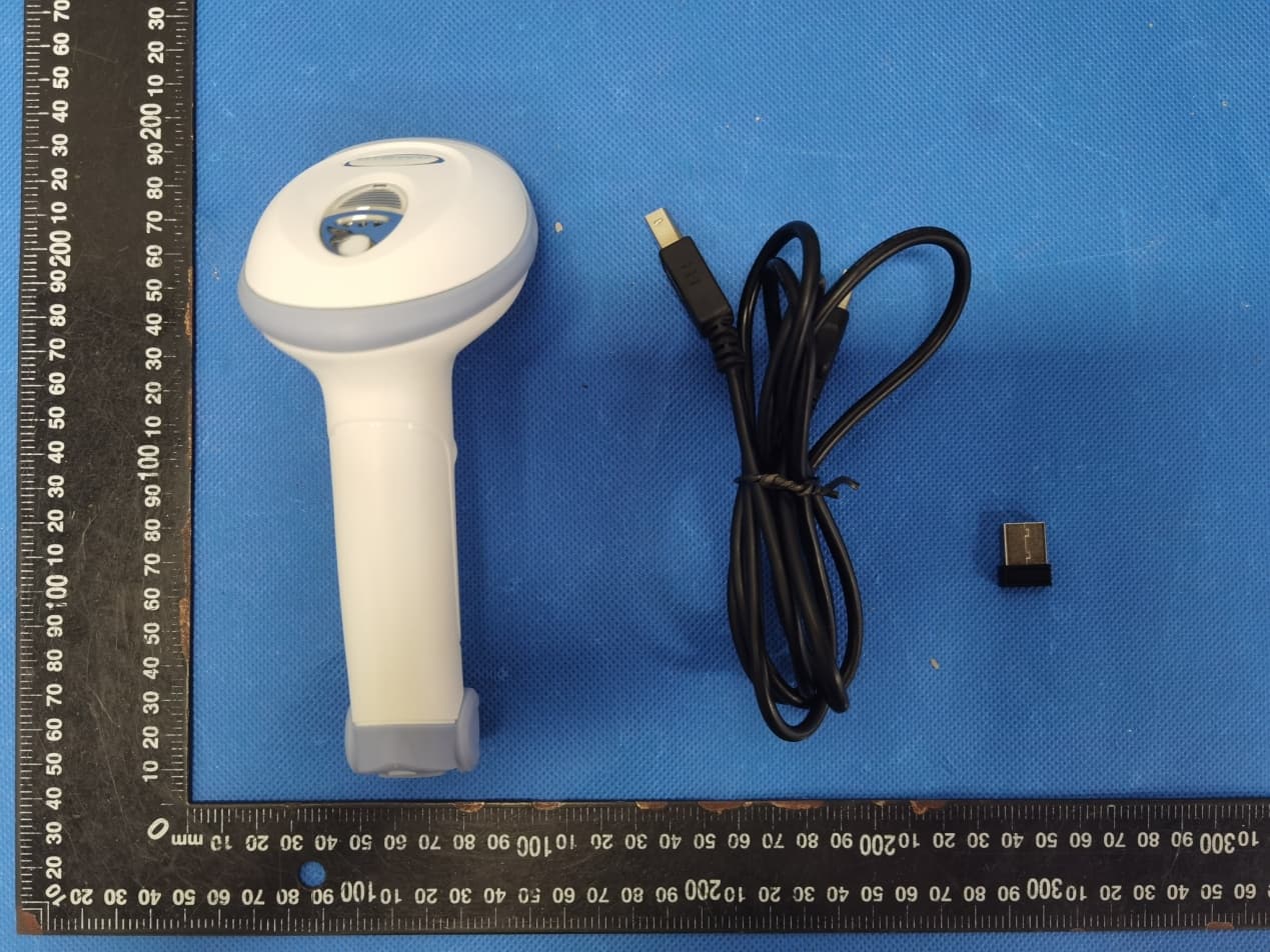
2AH6G-BR200BR300
Oct 08, 2022Barcode Scanner
Equipment Class
DXX - Part 15 Low Power Communication Device Transmitter