2AHCE-MON1Connect Monitor
Wellington Drive Technologies Ltd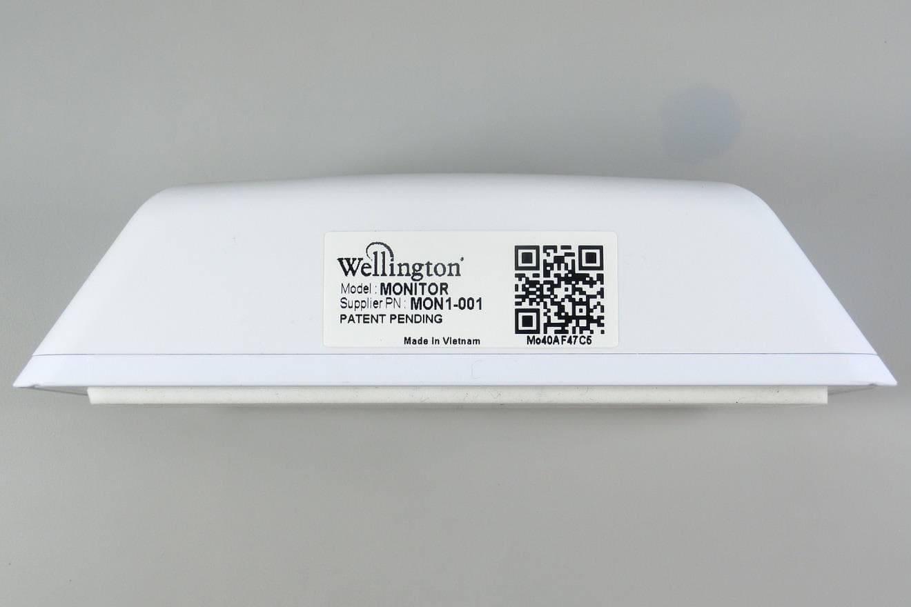
Click to zoom
Application Details
- Equipment Class
- DTS - Digital Transmission System
- Date of Grant
- Nov 23, 2020
- Application Purpose
- Original Equipment
- Date of Application
- Nov 19, 2020
- Equipment Note
- Connect Monitor
- Frequency Range
- 2402.00000000 - 2480.00000000
- Country
- New Zealand
Documents & Files
Document Text
Text extracted from the exhibit documents filed with the FCC. Open a document above to read the original.
Users Manual
© 2020 Wellington Drive Technologies Limited 21 Arrenway Dr, Albany, North Shore 0632, New Zealand PO Box 302-533, North Harbour, North Shore 0751, New Zealand P: +64 9 477 0415 Fax: +64 9 414 6591 E: [email protected] www.wdtl.com Connect™ Monitor Manual Document No: WT 9437 Issue Date: August 2020 ® is a registered Trade Mark of Wellington Drive Technologies Connect™ Monitor Instructions Manual AUGUST 2020 2 Warnings Please read the following warnings to maintain the safe operation and continued performance of your Wellington Drive Technologies Limited Connect Monitor: Warnings Important Do's and Don'ts Installation Installation of the Connect Monitor otherwise than in accordance with the “Description & Install” section of this manual will invalidate the warranty. The Connect Monitor must only be installed and configured by trained and authorized staff. Do not drop the Connect Monitor. No serviceable parts There are no serviceable parts inside the Connect Monitor. Do not attempt to open the housing. Opening of the electronics housing, altering, or modifying the Connect Monitor will invalidate the warranty and damage the device. There are no serviceable parts inside the Connect Monitor. Do not open the housing. Fit for purpose The Connect Monitor must only be used for the purposes and functions described in this manual. While Wellington Drive Technologies Limited may provide technical support on suitable applications and configurations of the Connect Monitor (where such a relationship may exist), no liability, responsibility or risk is accepted in determining if the Connect Monitor is fit for purpose for any particular application. No liability, responsibility or risk is accepted by Wellington Drive Technologies Limited for the correct operational function of any particular installation or configuration. The Connect Monitor must only be used for the purposes described in this manual. Continuous development Wellington Drive Technologies Limited undertakes to continuously develop and improve products and services. The design and specification of Connect Monitor is subject to change without notice. The contents of this manual are subject to change without warning. While every endeavor is made to ensure that all specifications and documents are current and complete, Wellington Drive Technologies Limited accepts no liability, responsibility or risk due to omissions or changes caused by continuous improvement and design changes. Users of this manual should verify that they have the latest version of the information (published on the Wellington Drive Technologies website www.wdtl.com) before proceeding. The design and specification of the Connect Monitor is subject to change without warning. Connect™ Monitor Instructions Manual AUGUST 2020 3 Correct disposal The Connect Monitor is subject to EU Directive 2012/19/EU (WEEE) for e- waste. It may also be subject to other national legislation for the safe disposal of e-waste. The Connect Monitor must not be disposed of in municipal collections; it must be disposed of through an approved WEEE collection point. Alternatively, Connect Monitor may be returned to an authorized Wellington Drive Technologies Limited distributor at the end of its working life. Penalties may be applicable for incorrect disposal, as specified by national legislation. The Connect Monitor must not be disposed of in municipal collections; it must be disposed of through an approved e- waste collection point. Safety warning: The Connect Monitor devices contain a lithium battery. This may be hazardous if incinerated or physically damaged. Chemicals The Connect Monitor must not be exposed to any solvents or chemicals, as this may damage the housing, leading to unsafe operation. Exposure to such chemicals invalidates the warranty. Temperature The Connect Monitor must only be subjected to temperatures as specified in the “Datasheet” and the “Technical Specification” section of this manual. Exceeding these ranges in operation, installation, transportation, or storage, will invalidate the warranty and may damage electronic circuits and housing components, leading to premature failure. Vibration and impact The unit must be installed in such a way as to be protected from impact in operation. Exposure to impact and mechanical shock, either in operation, installation, transportation, or storage, may damage electronic circuits and housing components, leading to premature failure, and may cause the Connect Monitor to become unsafe. Damage caused by impact is not covered by warranty. Do not drop the Connect Monitor. The device contains a lithium battery. This may be hazardous if incinerated or physically damaged. The circuit board may contain hazardous substances which could affect health and the environment if disposed of incorrectly. Connect Monitor complies with EU Directive 2011/65/EU (RoHS). Connect™ Monitor Instructions Manual AUGUST 2020 4 Introduction The Connect Monitor by Wellington is a battery operated self- contained Bluetooth LE transmission sensor hub designed for providing radio connectivity to existing refrigeration equipment in the market. It adds functionality such as telemetry connectivity, asset tracking, and proximity based marketing. Another unique feature is wireless connectivity to a mobile app that gives authorized Service Technicians full wireless access to data logging and troubleshooting. ➢ Mobile app with intuitive touch screen interface ➢ Wireless data logging and diagnostic control ➢ Compact size ➢ Built-in sensors ➢ Flexible installation Connect™ Monitor Instructions Manual AUGUST 2020 5 Process Overview The following process details the steps required for Connect Monitor installation, commissioning, and activation within the Wellington Connect ecosystem and reporting tools. The installation process is designed for different scenarios: • In-factory installation by equipment manufacturers; • Warehouse installation by customers; • Field installation by authorized pe…
Text truncated - open the document above for the full version.
RF Exposure Info
1 RF Exposure Compliance 1.1 Test Standards Test Specification Test item : Connect Monitor Identification / Type No. : Monitor FCC ID : 2AHCE-MON1 IC: 21145-MON1 HVIN : MONITOR Test standard : CFR47 FCC Part 2: Section 2.1093 CFR47 FCC Part 2: Section 1.1307 FCC KDB Publication 447498 v06 RSS-102 Issue 5 March 2015 Measurement Record: The minimum distance for the EUT is less than 5mm. 1.2 FCC RF Exposure Compliance Requirement Since maximum peak output power of the transmitter is 4.52 dBm ≈ 2.83 mW < 10 mW. Hence the EUT is excluded from SAR evaluation according to FCC KDB Publication 447498 D01 General RF Exposure Guidance v06. 1.3 IC RF Exposure Compliance Requirement 1.3.1 Standard Requirement According to RSS-102 Issue 5 March 2015 2.5.1 Exemption Limits for Routine Evaluation – SAR Evaluation SAR evaluation is required if the separation distance between the user and/or bystander and the antenna and/or radiating element of the device is less than or equal to 20 cm, except when the device operates at or below the applicable output power level (adjusted for tune-up tolerance) for the specified separation distance defined in Table 1. 1.3.2 Limits 1.3.3 EUT RF Exposure a) Stand-alone Operation Mode For BLE: Measurement Data Test mode : GFSK_1Mbps Channel Maximum Peak Conducted Output Power (dBm) Maximum Peak Conducted Output Power (mW) Limit (mW) Lowest (2402MHz) 4.52 2.831 <4mW Middle (2440MHz) 4.37 2.735 <4mW Highest (2480MHz) 4.36 2.729 <4mW Conclusion: E.i.r.p. calculation value <limit, SAR is exempted. Test mode : GFSK_2Mbps Channel Maximum Peak Conducted Output Power (dBm) Maximum Peak Conducted Output Power (mW) Limit (mW) Lowest (2402MHz) 4.40 2.754 <4mW Middle (2440MHz) 4.28 2.679 <4mW Highest (2480MHz) 4.29 2.685 <4mW Conclusion: E.i.r.p. calculation value <limit, SAR is exempted. Remark: 1) The Max Conducted Peak Output Power data refer to report Report No.: 60419852 001 For NFC: The worst case (refer to report 60419852 002) is below: Frequency (MHz) Level (dBμV/m) Output Power (dBm) Output Power (mW) Limit (mW) 13.56 47.88 -47.38 0.00002 71 So the SAR report is not required. b) Simultaneous Transmission Operation Mode Simultaneous transmission mode The sum of the ratios Result BLE + NFC 2.831/4+0.00002/71 0.708<1
Test Report
Prüfbericht - Produkte Test Report - Products Appendix B 60419852 001 Page 1 of 38 Appendix B: Test Results of BLE APPENDIX B: TEST RESULTS OF BLE ............................................................................................................................................ 1 APPENDIX B.1: TEST RESULTS OF CONDUCTED POWER SPECTRAL DENSITY ......................................................................................... 2 GFSK(BLE) Mode, 1Mbps...................................................................................................................................................... 2 GFSK(BLE) Mode, 2Mbps...................................................................................................................................................... 3 APPENDIX B.2: TEST RESULTS OF 6DB BANDWIDTH ......................................................................................................................... 5 GFSK(BLE) Mode, 1Mbps...................................................................................................................................................... 5 GFSK(BLE) Mode, 2Mbps...................................................................................................................................................... 8 APPENDIX B.3: TEST RESULTS OF 99% BANDWIDTH....................................................................................................................... 11 GFSK(BLE) Mode, 1Mbps.................................................................................................................................................... 11 GFSK(BLE) Mode, 2Mbps.................................................................................................................................................... 14 APPENDIX B.4: TEST RESULTS OF CONDUCTED SPURIOUS EMISSIONS MEASURED IN 100 KHZ BANDWIDTH......................................... 17 GFSK(BLE) Mode, 1Mbps.................................................................................................................................................... 17 GFSK(BLE) Mode, 2Mbps.................................................................................................................................................... 21 APPENDIX B.5: TEST RESULTS OF RADIATED SPURIOUS EMISSIONS .................................................................................................. 25 30 MHz to 1GHz .................................................................................................................................................................. 25 1GHz-18GHz ........................................................................................................................................................................ 29 APPENDIX B.6: TEST RESULTS OF RADIATED EMISSIONS IN RESTRICTED BANDS ................................................................................. 35 Prüfbericht - Produkte Test Report - Products Appendix B 60419852 001 Page 2 of 38 Appendix B.1: Test Results of Conducted Power Spectral Density GFSK(BLE) Mode, 1Mbps Prüfbericht - Produkte Test Report - Products Appendix B 60419852 001 Page 3 of 38 GFSK(BLE) Mode, 2Mbps Prüfbericht - Produkte Test Report - Products Appendix B 60419852 001 Page 4 of 38 Prüfbericht - Produkte Test Report - Products Appendix B 60419852 001 Page 5 of 38 Appendix B.2: Test Results of 6dB Bandwidth GFSK(BLE) Mode, 1Mbps Prüfbericht - Produkte Test Report - Products Appendix B 60419852 001 Page 6 of 38 Prüfbericht - Produkte Test Report - Products Appendix B 60419852 001 Page 7 of 38 Prüfbericht - Produkte Test Report - Products Appendix B 60419852 001 Page 8 of 38 GFSK(BLE) Mode, 2Mbps Prüfbericht - Produkte Test Report - Products Appendix B 60419852 001 Page 9 of 38 Prüfbericht - Produkte Test Report - Products Appendix B 60419852 001 Page 10 of 38 Prüfbericht - Produkte Test Report - Products Appendix B 60419852 001 Page 11 of 38 Appendix B.3: Test Results of 99% Bandwidth GFSK(BLE) Mode, 1Mbps Prüfbericht - Produkte Test Report - Products Appendix B 60419852 001 Page 12 of 38 Prüfbericht - Produkte Test Report - Products Appendix B 60419852 001 Page 13 of 38 Prüfbericht - Produkte Test Report - Products Appendix B 60419852 001 Page 14 of 38 GFSK(BLE) Mode, 2Mbps Prüfbericht - Produkte Test Report - Products Appendix B 60419852 001 Page 15 of 38 Prüfbericht - Produkte Test Report - Products Appendix B 60419852 001 Page 16 of 38 Prüfbericht - Produkte Test Report - Products Appendix B 60419852 001 Page 17 of 38 Appendix B.4: Test Results of Conducted Spurious Emissions Measured in 100 kHz Bandwidth GFSK(BLE) Mode, 1Mbps Low Channel: Prüfbericht - Produkte Test Report - Products Appendix B 60419852 001 Page 18 of 38 Middle Channel: Prüfbericht - Produkte Test Report - Products Appendix B 60419852 001 Page 19 of 38 High Channel: Prüfbericht - Produkte Test Report - Products Appendix B 60419852 001 Page 20 of 38 Band Edge, Low Channel: Band Edge, High Channel: Prüfbericht - Produkte Test Report - Products Appendix B 60419852 001 Page 21 of 38 GFSK(BLE) Mode, 2Mbps Low Channel: Prüfbericht - Produkte Test Report - Products Appendix B 60419852 001 Page 22 of 38 Middle Channel: Prüfbericht - Produkte Test Report - Products Appendix B 60419852 001 Page 23 of 38 High Channel: Prüfbericht - Produkte Test Report - Products Appendix B 60419852 001 Page 24 of 38 Band Edge, Low Channel: Band Edge, High Channel: Prüfbericht - Produkte Test Report - Products Appendix B 60419852 001 Page 25 of 38 Appendix B.5: Test Results of Radiated Spurious Emissions Note: 1) T his testing was carried out on different modulations, but only the worst case was presented in this report. 2) T esting was carried out within frequency range 9kHz to the tenth harmonics. T he measurement results below 30MHz and 18GHz - 26.5GHz were greater than 20dB below the limit, so only the radiated spurious emissions from 30MHz to 18GHz …
Text truncated - open the document above for the full version.
Test Report
Prüfbericht - Produkte Test Report - Products Prüfbericht-Nr.: Test report no.: 60419852 001 A uftrags-Nr.: Order no.: 168279017 Seite 1 von 20 Page 1 of 20 Kunden-Referenz-Nr.: Client reference no.: N/A A uftragsdatum: Order date: 2020-08-21 Auftraggeber: Client: Wellington Drive Technologies 21 Arrenway Drive, Rosedale, Auckland, New Zealand, 0632 Prüfgegenstand: Test item: Connect Monitor Bezeichnung / Typ-Nr.: Identification / Type no.: Monitor (Trademark: Connect IoT, Wellington) Auftrags-Inhalt: Order content: FCC and IC approval Prüfgrundlage: Test specification: CFR47 FCC Part 15: Subpart C Section 15.247 CFR47 FCC Part 15: Subpart C Section 15.209 CFR47 FCC Part 2: Section 2.1091 RSS-247 Issue 2 February 2017 RSS-Gen Issue 5 April 2018 RSS-102 Issue 5 March 2015 Wareneingangsdatum: Date of sample receipt: 2020-09-02 Please refer to photo documents Prüfmuster-Nr.: Test sample no.: A002899729-003 to 005 Prüfzeitraum: Testing period: 2020-09-03 - 2020-09-27 Ort der Prüfung: Place of testing: TÜV Rheinland (Shenzhen) Co., Ltd. Prüflaboratorium: Testing laboratory: TÜV Rheinland (Shenzhen) Co., Ltd. Prüfergebnis*: Test result*: Pass geprüft von: tested by: genehmigt von: a uthorized by: Datum: Date: 2020-11-18 Ausstellungsdatum: I ssue date: 2020-11-18 Stellung / Position Jackson Yang / Project Engineer Stellung / Position Winnie Hou / Technical Certifier Sonstiges / Other: FCC ID: 2AHCE-MON1 IC: 21145-MON1 HVIN: MONITOR Zustand des Prüfgegenstandes bei Anlieferung: Condition of the test item at delivery: Prüfmuster vollständig und unbeschädigt Test item complete and undamaged: * Legende: 1 = sehr gut 2 = gut 3 = befriedigend 4 = ausreichend 5 = mangelhalt P(ass) = entspricht o.g. Prüfgrundlage(n) F(ail) = entspricht nicht o.g. Prüfgrundlage(n) N/A = nicht anwendbar N/T = nicht getestet Legend: 1 = very good 2 = good 3 = satisfactory 4 = sufficient 5 = poor P(ass) = passed a.m. test specifications(s) F(ail) = failed a.m. test specifications(s) N/A = not applicable N/T = not tested Dieser Prüfbericht bezieht sich nur auf das o.g. Prüfmuster und darf ohne Genehmigung der Prüfstelle nicht auszugsweise vervielfältigt werden. Dieser Bericht berechtigt nicht zur Verwendung eines Prüfzeichens. This test report only relates to the a. m. test sample. Without permission of the test center this test report is not permitted to be V05 duplicated in extracts. This test report does not entitle to carry any test mark. TUV Rheinland (Shenzhen) Co., Ltd. 1601 R&D Room, 1602 -1604, 17-18F, Building 7 Site C, Vanke Cloud City Phase I, Xingke First Street, Xili Street, Xili Community, Nanshan District, Shenzhen 518052, P.R. China Mail: [email protected] http://www.tuv.com Prüfbericht - Produkte Test Report - Products Prüfbericht - Nr.: Test Report No. 60419852 001 Seite 2 von 20 Page 2 of 20 Test Summary 5.1.1 ANTENNA REQUIREMENT RESULT: Pass 5.1.2 MAXIMUM PEAK CONDUCTED OUTPUT POWER RESULT: Pass 5.1.3 CONDUCTED POWER SPECTRAL DENSITY RESULT: Pass 5.1.4 6DB BANDWIDTH RESULT: Pass 5.1.5 99% BANDWIDTH RESULT: Pass 5.1.6 CONDUCTED SPURIOUS EMISSIONS MEASURED IN 100 KHZ BANDWIDTH RESULT: Pass 5.1.7 RADIATED SPURIOUS EMISSION RESULT: Pass Prüfbericht - Produkte Test Report - Products Prüfbericht - Nr.: Test Report No. 60419852 001 Seite 3 von 20 Page 3 of 20 Contents 1 GENERAL REMARKS ........................................................................................................................... 4 1.1 COMPLEMENTARY MATERIALS ............................................................................................................ 4 2 TEST SITES ........................................................................................................................................ 5 2.1 TEST FACILITIES ................................................................................................................................. 5 2.2 LIST OF TEST AND MEASUREMENT INSTRUMENTS................................................................................. 5 2.3 TRACEABILITY .................................................................................................................................... 6 2.4 CALIBRATION ..................................................................................................................................... 6 2.5 MEASUREMENT UNCERTAINTY............................................................................................................. 6 2.6 LOCATION OF ORIGINAL DATA ............................................................................................................. 6 2.7 STATUS OF FACILITY USED FOR TESTING ............................................................................................. 7 3 GENERAL PRODUCT INFORMATION ...................................................................................................... 8 3.1 PRODUCT FUNCTION AND INTENDED USE ............................................................................................. 8 3.2 RATINGS AND SYSTEM DETAILS .......................................................................................................... 8 3.3 INDEPENDENT OPERATION MODES ...................................................................................................... 9 3.4 NOISE GENERATING AND NOISE SUPPRESSING PARTS ......................................................................... 9 3.5 SUBMITTED DOCUMENTS..................................................................................................................... 9 4 TEST SET-UP AND OPERATION MODES ..............................................................................................10 4.1 PRINCIPLE OF CONFIGURATION SELECTION .......................................................................................10 4.2 TEST OPERATION AND TEST SOFTWARE ............................................................................................10 4.3 SPECIAL ACCESSORIES AND AUXILIARY EQUIPMENT .…
Text truncated - open the document above for the full version.
Test Setup Photos
Prüfbericht - Produkte Test Report - Products Appendix A 60419852 001 Page 1 of 2 Appendix A: Photographs of the Test Set-Up APPENDIX A: PHOTOGRAPHS OF THE TEST SET-UP.................................................................................................................. 1 PHOTOGRAPH 1: SET-UP PHOTO FOR RADIATED SPURIOUS EMISSION, 30MHZ - 1GHZ ......................................................................... 2 PHOTOGRAPH 2: SET-UP PHOTO FOR RADIATED SPURIOUS EMISSION, ABOVE 1GHZ ............................................................................. 2 Prüfbericht - Produkte Test Report - Products Appendix A 60419852 001 Page 2 of 2 Photograph 1: Set-up photo for Radiated Spurious Emission, 30MHz - 1GHz Photograph 2: Set-up photo for Radiated Spurious Emission, Above 1GHz
Contact Information
Applicant
Marc Tinsel(Head of Manufacturing)
Technical Contact
Test Firm
TUV Rheinland (Shenzhen) Co., Ltd.Gina Yang
[email protected]86 755 8268 1497
Technical Specifications
| # | Rule Parts | Frequency Range | Power Output |
|---|---|---|---|
| 1 | 15C | 2.40 GHz - 2.48 GHz | 2.80 mW |
Other Applications from Wellington Drive Technologies Ltd
2AHCE-SCS2
Mar 26, 2026Cellular Connected Controller
Equipment Class
DTS - Digital Transmission System
2AHCE-GW2
Nov 28, 2025Gateway
Equipment Class
DTS - Digital Transmission System